EP1541504A1 - Convoyeur élévateur pour la séparation des articles de série, particulièrement des piles de capsules de bouteille, et procédure correspondante - Google Patents
Convoyeur élévateur pour la séparation des articles de série, particulièrement des piles de capsules de bouteille, et procédure correspondante Download PDFInfo
- Publication number
- EP1541504A1 EP1541504A1 EP03028463A EP03028463A EP1541504A1 EP 1541504 A1 EP1541504 A1 EP 1541504A1 EP 03028463 A EP03028463 A EP 03028463A EP 03028463 A EP03028463 A EP 03028463A EP 1541504 A1 EP1541504 A1 EP 1541504A1
- Authority
- EP
- European Patent Office
- Prior art keywords
- container
- rows
- elevator according
- conveyor
- conveying
- Prior art date
- Legal status (The legal status is an assumption and is not a legal conclusion. Google has not performed a legal analysis and makes no representation as to the accuracy of the status listed.)
- Granted
Links
- 238000000034 method Methods 0.000 title claims description 9
- 230000003028 elevating effect Effects 0.000 title 1
- 239000002775 capsule Substances 0.000 claims description 14
- 238000012545 processing Methods 0.000 claims description 10
- 238000012546 transfer Methods 0.000 claims description 2
- 238000013461 design Methods 0.000 description 4
- 230000015572 biosynthetic process Effects 0.000 description 3
- 230000000694 effects Effects 0.000 description 3
- 238000004519 manufacturing process Methods 0.000 description 2
- 238000012544 monitoring process Methods 0.000 description 2
- 238000012805 post-processing Methods 0.000 description 2
- 238000000926 separation method Methods 0.000 description 2
- 230000009286 beneficial effect Effects 0.000 description 1
- 239000013590 bulk material Substances 0.000 description 1
- 230000003247 decreasing effect Effects 0.000 description 1
- 230000001627 detrimental effect Effects 0.000 description 1
- 238000011143 downstream manufacturing Methods 0.000 description 1
- 238000003780 insertion Methods 0.000 description 1
- 230000037431 insertion Effects 0.000 description 1
- 230000000630 rising effect Effects 0.000 description 1
- 238000005096 rolling process Methods 0.000 description 1
Images


Classifications
-
- B—PERFORMING OPERATIONS; TRANSPORTING
- B65—CONVEYING; PACKING; STORING; HANDLING THIN OR FILAMENTARY MATERIAL
- B65G—TRANSPORT OR STORAGE DEVICES, e.g. CONVEYORS FOR LOADING OR TIPPING, SHOP CONVEYOR SYSTEMS OR PNEUMATIC TUBE CONVEYORS
- B65G47/00—Article or material-handling devices associated with conveyors; Methods employing such devices
- B65G47/02—Devices for feeding articles or materials to conveyors
- B65G47/04—Devices for feeding articles or materials to conveyors for feeding articles
- B65G47/12—Devices for feeding articles or materials to conveyors for feeding articles from disorderly-arranged article piles or from loose assemblages of articles
- B65G47/14—Devices for feeding articles or materials to conveyors for feeding articles from disorderly-arranged article piles or from loose assemblages of articles arranging or orientating the articles by mechanical or pneumatic means during feeding
- B65G47/1407—Devices for feeding articles or materials to conveyors for feeding articles from disorderly-arranged article piles or from loose assemblages of articles arranging or orientating the articles by mechanical or pneumatic means during feeding the articles being fed from a container, e.g. a bowl
- B65G47/1442—Devices for feeding articles or materials to conveyors for feeding articles from disorderly-arranged article piles or from loose assemblages of articles arranging or orientating the articles by mechanical or pneumatic means during feeding the articles being fed from a container, e.g. a bowl by means of movement of the bottom or a part of the wall of the container
- B65G47/1471—Movement in one direction, substantially outwards
Definitions
- the invention relates to an elevator arranged in series, one inside the other inserted mass-produced articles, in particular nested bottle capsules. It further relates to a method for separating the rows of series-arranged, nested mass articles, in particular into each other popped bottle caps.
- nested mass articles are in particular to Conical mass products, such as cups, lids, bottle caps. These will usually stored in a stacking unit using pallets, on which a plurality of juxtaposed rows into each other rested masses rest. The respective overhead pallet is supported either directly on the rows underneath one another Mass products, or on the arranged under the pallet range immediately.
- Such stacking units are, for example, in DE 198 44 834 A1 and DE 100 56 422 A1.
- Elevators are known from practice, the funding for conveying sporadic discontinued bottle caps, such as crown caps have.
- the bottle caps are poured into a container and then taken from the funding, promoted by this up and one Post-processing station, in particular a closing machine for the Supplied bottles.
- the object of the present invention is first of all to provide an elevator with the stacked rows of stacked mass products, re the rows can be safely separated, without the mass articles too damage, and to remove these isolated rows for further processing. It is another object to provide a method that allows a Variety of juxtaposed in a transport container rows mass-produced articles, without a pallet between the rows is arranged to separate and supply to a further processing station.
- the elevator according to the invention is suitable, the plurality loosely arranged in the container Series of melded mass products with respect to the rows to separate.
- An essential feature of the elevator here is in the Arrangement of the circulating conveyor in the lower region. Because of this is arranged obliquely upwards, and thus the respective chamber when driving the conveyor is moved obliquely from the bottom up, the chambers are passed by the rows, until a row into each other Mauled mass article falls down into a chamber. This in the chamber taken row is then at the other rows in the container pasted mass article, if the level of the Container is accordingly.
- the occupancy of each chamber is random. It can be quite a chamber when moving past the Kammem the rows nested mass products in the container is not filled or only filled very late.
- the chambers fill up already in the range of the lower deflection of the conveyor.
- the in the Chambers located rows of nested mass products are about the top dead center of the circulating conveyor out and funded there inevitably spent, for example, on a magazine of a finishing station or a conveyor belt, in particular a horizontal conveyor belt, which ab includet the respective isolated series. This causes the slip Rows automatically in the area of the upper deflection from the individual chambers for direct feed to the downstream processing machine.
- the chambers extend horizontally in their longitudinal direction.
- the chambers are formed so that they are substantially horizontal in their longitudinal direction extend.
- the term "substantially horizontal” is to be interpreted broadly.
- the angle of inclination relative to the horizontal can be up to about 30 ° be. If the chambers are inclined relative to the horizontal, in particular an exact abutment of one end of each row at a stop causes the elevator. This exact positioning is beneficial for the Further processing of the series.
- the obliquely upwardly directed portion of the conveyor is preferably just trained.
- said portion of the conveyor belt advantageous to a pressure relief the rows to be taken up by the chambers. This would not be the case if the section would be horizontal. In this case, the burden would be all lying above the respective chamber rows on the bottom row, which should fall into one of the moving chambers.
- Straight Formation of the obliquely upward portion of the conveyor is under the aspect of pressure relief advantage.
- the oblique section of the Conveying means is at an angle of 20 ° to 40 °, preferably 25 ° to 35 °, in particular 30 ° to the horizontal. It is quite conceivable that form obliquely upward section of the conveyor slightly curved, with a curvature of the rows in the container into each other put away mass-produced goods.
- a curved portion of the conveying means is located at the top of the obliquely upwardly directed portion of the conveyor followed.
- the curved one Section of the conveyor requires a further pressure relief, so that at the latest there the filling of the chamber takes place.
- the conveyor preferably closes a straight section of the Conveyor, in particular a vertically arranged straight portion of the Conveying means.
- the vertically arranged straight section allows it is possible to achieve a high delivery height with a small footprint of the elevator. It can be designed so that the upper straight section the conveyor with its lower end still within the container located.
- the length of the respective chamber and / or the extent is expedient of the space enclosed by the container, seen in the longitudinal direction of the chambers, slightly larger than the length of each row into each other put masses. But there must be so much difference in length between the Series of melded mass products and the length of each chamber remain that a safe insertion of the respective row into the chamber is guaranteed, even if they are not exactly inside the container is aligned. In this respect, the dimensions of containers and chambers, as well as their To coordinate orientation to each other.
- the lower deflection region is in particular adjacent to a wall of the Container arranged.
- a wall of the Container arranged.
- only a small gap between the Chamber boundaries and the wall of the container provided. hereby it is ensured that when deflecting the conveyor in the lower deflection no row between the conveyor and the wall of the container can fall through.
- the respective chamber by two with The conveyor-connected strips is formed, can by a small Gap formation between the strip and the wall of the container is optimal Receiving a series of stacked bulk goods can be achieved. This is to be seen in particular from the aspect that at the deflection in the lower deflection, the strips spread apart, thus the respective chamber has a larger cross-section.
- the trailing splayed Strip preferably bridges the distance to the wall of the container, with a small gap to the container.
- the distance between adjacent strips is preferably slightly larger than that maximum diameters of the series of nested mass-produced articles. He should but only so much bigger that introducing the series safely between neighboring strips can proceed.
- the extension of each Chamber in the direction perpendicular to the conveying direction and the chamber longitudinal axis should be about as large as the maximum diameter of the row into each other put masses. It is not detrimental if the series partially off the chamber sticks out. This additionally requires a straightening effect for the rows stacked bulk goods that are still in the container.
- the conveyor may be designed differently, for example as a conveyor belt or as a toothed belt. It is considered to be particularly advantageous if the conveyor is designed as a toothed belt to which the strips attached are. In particular, two toothed belts are provided on which the strips in Area whose two ends are attached. Appropriately, additional guidance means provided for the timing belt between the deflection areas. Basically, the funding is arbitrary. There are also chains as a subsidy in question. These do not have to be standard chains, but special chains can be used.
- the respective chamber is particular formed between the two adjacent strips and the conveyor belt.
- the respective chamber preferably between the two strips and one Wall of the elevator - thus a stationary wall - formed, the Wall is arranged parallel to the transport direction of the conveyor.
- the funding can completely have the chambers, whereby no stationary wall is provided, special this wall is integrated into the funding.
- sensor means are provided for detecting the occupancy the respective chamber and / or the occupancy of the conveying conveyor belt and / or the occupancy of the magazine. Especially under the Aspect of the chambers is thus a function monitoring and filling monitoring intended.
- the many rows of nested mass products be transferred loosely into the container. This is done in particular by Pouring the rows next to each other into a transport container the container.
- the task direction of the rows is not arbitrary.
- the rows of nested mass products are so in the container given that the longitudinal axis of the rows are substantially parallel to the rows Deflection axes of the conveyor comes to rest. These axes are parallel to an axis transverse to the conveying direction when conveying the isolated Row to further processing station is.
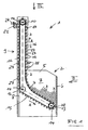
- the elevator 1 has a container 2 for receiving a plurality of rows 3 nested, conical bottle caps 4.
- the respective row 4 is the same length, it consists for example of 150 into each other popped bottle caps.
- the container 2 has a rectangular base and its two side walls are numbered 5, the front wall denoted by the reference numeral 6 and the rear wall by the reference numeral 8. Of the Interior 7 of the container 2 serves to receive a plurality of rows. 3 nested bottle caps 4.
- the length of each row 3 is slightly smaller than the clear distance of the two side walls 5 of the container 2.
- the rows 3 are filled in the container 2 so that they with their Longitudinal axis are positioned substantially parallel to the front wall 6.
- the elevator 1 In the area of the rear wall 8 of the container 2, adjacent to its side walls 5, the elevator 1 has two vertically extending uprights 9. In the area the upper ends of the uprights 9 are mounted in these a drive shaft 10, by means of a flanged to one of the stator 9 electric motor with reduction gear 11 is drivable.
- a bearing shaft 12 in the side walls 5 of the container. 2 In vertical alignment of the drive shaft 10th is in the container 2, a bearing shaft 12 in the side walls 5 of the container. 2 stored. Tilted at an angle of 30 ° to the horizontal, thus below the level of the bearing shaft 12 is adjacent to the front wall 6 of the container 2 another bearing shaft 13 is mounted in the side walls 5 of the container 2.
- With the drive shaft 10 are, in the region of the two stator 9, two gears 14th rotatably connected to the drive shaft 10.
- the guide on the front of the elevator 1 takes place, starting from a straight lower portion 17, via a curved Area 18 in a straight vertical area 19.
- Timing belt 15 closes a rear vertical region 20, along which the strips 16 are conveyed, Further, between the bearing shafts 12 and 13 an obliquely downwardly inclined Area 21, which runs parallel to the area 17. According to the course of the Areas 17 to 21 is immediately adjacent to the strips 16 in the areas 17, 18 and 19, behind the ledges, one from the bevel over the curvature provided in the vertical curved sheet 22. In the promotion thus run the strips 16 at a constant distance to the plate 22 over.
- Each bar 16 is suitable, in the promotion up, a number 3 into each other put under the bottle caps 4 and thus go up to promote, until the top dead center of the conveyor.
- Figure 4 is illustrated how after exceeding the top dead center a series of 4 nested bottle caps from the now after down-promoted bar 16 is delivered.
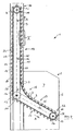
- the output is done in parallel arranged to strip 16 conveyor belt 23, which is the output row 3 of nested bottle caps 4 a further processing station supplies.
- Sensors 24 detect the transfer position of the conveyor belt 23 and a discharge position, so as to ensure that a row 3 nested bottle capsules 4 only from the elevator 1 on the conveyor belt 23 is issued when this area of the conveyor belt is free. Otherwise, the elevator 1 is stopped.
- the elevator in turn shows in Range of vertical conveyor line for the rows 3 nested Bottle caps 4 two sensors 25 on which determine whether on the respective Strip 16 a row 23 nested bottle caps 4 rests.
- the Energy and control cabinet 26 of the elevator 1 is in the region of one side of the Container 2 is arranged.
- the sensors 25 can be detected directly, whether the respective formed between adjacent strips 16 chamber 27th occupied by a series of 3 nested bottle capsules 4. Again Representation of the figures is to be found, based on the delivery side of the elevator 1, some chambers 27 are not occupied (FIGS. 1 and 2).
- the rows are 3 nested bottle capsules 4 abandoned as bulk material. These are for example in a transport container 100, tightly arranged rows 3 loose in the transport container inserted, thus without the intermediate layer / pallet, as it from the State of the art is known.
- the transport container is emptied, so that the Rows of 3 nested bottle capsules 4, as illustrated in FIG. 1, with its longitudinal axis parallel to the front wall 6 of the container 2 come lie. There are therefore a plurality of rows one above the other, which contact the conveyor, virtually the bottom of the container 2.
- the direction of rotation of the conveyor is illustrated by the arrow A.
- the Area 17 of the conveyor is the Area 17 of the conveyor at an angle of 30 ° to the horizontal arranged.
- the chambers 27 extend horizontally.
- the elevator 1 the design and arrangement the last 16 and the dimensions of the chamber to:
- the respective Chamber 27 is formed by two strips 16 connected to the toothed belt 15.
- the distance between adjacent bars is slightly larger than the maximum Diameter of the series 3 nested bottle caps 4.
- the Extension of the respective chamber 27 in the direction perpendicular to the conveying direction and to the chamber longitudinal axis is about as large as the maximum diameter the rows of 3 nested bottle caps 4. Is the diameter larger, the rows 3 protrude thus slightly above the front alignment of the strips addition, there is a positive straightening effect in the areas 17 and 18, since the rows in the chambers to the other adjacent rows act that have not yet fallen into a chamber.
- Behind is the respective Chamber 27 bounded by the wall 22.
- FIG. 5 discloses a detail of the strips 16.
- the surface 29 of the strip 16 contacted with the series 3 nested bottle capsules 4, even and runs, based on the respective chamber 27 at an angle of about 70 ° to the conveying plane 30 of the conveying means, said conveying plane 30 perpendicular to the plane of the sheet as shown in Figure 5 extends.
- the respective bar 16 has a leading, outer surface 31 which is vertical is arranged to the conveying plane of the conveyor. This design requires that over the surface 31, the row 3 in the region of the container 2 without Damage can be taken over and by means of the surface 29 inclined is secured against rolling out of the chamber 27.
Landscapes
- Engineering & Computer Science (AREA)
- Mechanical Engineering (AREA)
- Branching, Merging, And Special Transfer Between Conveyors (AREA)
- Filling Of Jars Or Cans And Processes For Cleaning And Sealing Jars (AREA)
- Combined Means For Separation Of Solids (AREA)
- Specific Conveyance Elements (AREA)
Priority Applications (4)
| Application Number | Priority Date | Filing Date | Title |
|---|---|---|---|
| EP03028463A EP1541504B1 (fr) | 2003-12-12 | 2003-12-12 | Convoyeur élévateur pour la séparation des articles de série, particulièrement des piles de capsules de bouteille, et procédure correspondante |
| DE50303866T DE50303866D1 (de) | 2003-12-12 | 2003-12-12 | Steilförderer zum Vereinzeln von Massenartikeln, insbesondere Stapel von Flaschenkapseln, sowie entsprechendes Verfahren |
| ES03028463T ES2266710T3 (es) | 2003-12-12 | 2003-12-12 | Transportador elevador para la separacion de articulos de serie, espe cialmente de pilas de caperuzas de botellas, asi como procedimiento correspondiente. |
| AT03028463T ATE329864T1 (de) | 2003-12-12 | 2003-12-12 | Steilförderer zum vereinzeln von massenartikeln, insbesondere stapel von flaschenkapseln, sowie entsprechendes verfahren |
Applications Claiming Priority (1)
| Application Number | Priority Date | Filing Date | Title |
|---|---|---|---|
| EP03028463A EP1541504B1 (fr) | 2003-12-12 | 2003-12-12 | Convoyeur élévateur pour la séparation des articles de série, particulièrement des piles de capsules de bouteille, et procédure correspondante |
Publications (2)
| Publication Number | Publication Date |
|---|---|
| EP1541504A1 true EP1541504A1 (fr) | 2005-06-15 |
| EP1541504B1 EP1541504B1 (fr) | 2006-06-14 |
Family
ID=34486182
Family Applications (1)
| Application Number | Title | Priority Date | Filing Date |
|---|---|---|---|
| EP03028463A Expired - Lifetime EP1541504B1 (fr) | 2003-12-12 | 2003-12-12 | Convoyeur élévateur pour la séparation des articles de série, particulièrement des piles de capsules de bouteille, et procédure correspondante |
Country Status (4)
| Country | Link |
|---|---|
| EP (1) | EP1541504B1 (fr) |
| AT (1) | ATE329864T1 (fr) |
| DE (1) | DE50303866D1 (fr) |
| ES (1) | ES2266710T3 (fr) |
Cited By (8)
| Publication number | Priority date | Publication date | Assignee | Title |
|---|---|---|---|---|
| CN104139963A (zh) * | 2013-05-07 | 2014-11-12 | 广东隆兴包装实业有限公司 | 圆柱形曲面印刷机的自动提升送料装置 |
| CN104648965A (zh) * | 2015-01-07 | 2015-05-27 | 于振中 | 一种提升对夹上料机 |
| CN106429158A (zh) * | 2016-08-31 | 2017-02-22 | 上海三禾服装物流设备制造有限公司 | 垂直投送系统 |
| CN110562510A (zh) * | 2019-09-17 | 2019-12-13 | 赖进九 | 一种压铸件包装设备 |
| CN112518405A (zh) * | 2020-11-23 | 2021-03-19 | 浙江冠利新材料股份有限公司 | 一种铝制瓶盖进料机构 |
| AT507740B1 (de) * | 2008-07-16 | 2021-07-15 | Gassner Gmbh | Sortiergerät |
| CN113633013A (zh) * | 2021-09-09 | 2021-11-12 | 江西中烟工业有限责任公司 | 一种适用于切梗丝机设备的烟梗定向排列喂料装置 |
| CN114195065A (zh) * | 2021-11-25 | 2022-03-18 | 启东曦瑞新材料科技有限公司 | 一种用于改性水处理试剂的制备系统及其工作方法 |
Families Citing this family (1)
| Publication number | Priority date | Publication date | Assignee | Title |
|---|---|---|---|---|
| US9376301B1 (en) | 2015-07-16 | 2016-06-28 | Jalbert Automatisation Inc. | Adjustable cap sorter |
Citations (2)
| Publication number | Priority date | Publication date | Assignee | Title |
|---|---|---|---|---|
| US4830171A (en) * | 1986-08-03 | 1989-05-16 | W. Schlafhorst & Co. | Apparatus for providing a constant bobbin tube supply |
| DE10052062A1 (de) * | 1999-10-19 | 2001-09-27 | Gassner Gmbh | Sortiergerät |
-
2003
- 2003-12-12 AT AT03028463T patent/ATE329864T1/de not_active IP Right Cessation
- 2003-12-12 EP EP03028463A patent/EP1541504B1/fr not_active Expired - Lifetime
- 2003-12-12 DE DE50303866T patent/DE50303866D1/de not_active Expired - Fee Related
- 2003-12-12 ES ES03028463T patent/ES2266710T3/es not_active Expired - Lifetime
Patent Citations (2)
| Publication number | Priority date | Publication date | Assignee | Title |
|---|---|---|---|---|
| US4830171A (en) * | 1986-08-03 | 1989-05-16 | W. Schlafhorst & Co. | Apparatus for providing a constant bobbin tube supply |
| DE10052062A1 (de) * | 1999-10-19 | 2001-09-27 | Gassner Gmbh | Sortiergerät |
Cited By (10)
| Publication number | Priority date | Publication date | Assignee | Title |
|---|---|---|---|---|
| AT507740B1 (de) * | 2008-07-16 | 2021-07-15 | Gassner Gmbh | Sortiergerät |
| CN104139963A (zh) * | 2013-05-07 | 2014-11-12 | 广东隆兴包装实业有限公司 | 圆柱形曲面印刷机的自动提升送料装置 |
| CN104648965A (zh) * | 2015-01-07 | 2015-05-27 | 于振中 | 一种提升对夹上料机 |
| CN106429158A (zh) * | 2016-08-31 | 2017-02-22 | 上海三禾服装物流设备制造有限公司 | 垂直投送系统 |
| CN106429158B (zh) * | 2016-08-31 | 2024-03-19 | 上海三禾服装物流设备制造有限公司 | 垂直投送系统 |
| CN110562510A (zh) * | 2019-09-17 | 2019-12-13 | 赖进九 | 一种压铸件包装设备 |
| CN112518405A (zh) * | 2020-11-23 | 2021-03-19 | 浙江冠利新材料股份有限公司 | 一种铝制瓶盖进料机构 |
| CN113633013A (zh) * | 2021-09-09 | 2021-11-12 | 江西中烟工业有限责任公司 | 一种适用于切梗丝机设备的烟梗定向排列喂料装置 |
| CN114195065A (zh) * | 2021-11-25 | 2022-03-18 | 启东曦瑞新材料科技有限公司 | 一种用于改性水处理试剂的制备系统及其工作方法 |
| CN114195065B (zh) * | 2021-11-25 | 2024-02-20 | 长三角(义乌)生态环境研究中心 | 一种用于改性水处理试剂的制备系统及其工作方法 |
Also Published As
| Publication number | Publication date |
|---|---|
| DE50303866D1 (de) | 2006-07-27 |
| ATE329864T1 (de) | 2006-07-15 |
| EP1541504B1 (fr) | 2006-06-14 |
| ES2266710T3 (es) | 2007-03-01 |
Similar Documents
| Publication | Publication Date | Title |
|---|---|---|
| EP2585375B1 (fr) | Machine pour transporter une pile de boites a oeufs ouvertes, ainsi qu' un appareil de separation des boites et un dispositif d'empilage des boites videes | |
| EP2874926B1 (fr) | Procede et dispositif de chargement d'une palette | |
| EP3115322A1 (fr) | Procede et dispositif destines a la depalettisation de pneus | |
| EP0668027A2 (fr) | Procédé et dispositif pour la manipulation de conteneurs recevant des récipients avec des cigarettes | |
| EP3006379A2 (fr) | Goulotte de transport pour un automate de preparation de commande pour les pharmacies et dispositif de transport, plateau rotatif et automate de preparation de commande pour pharmacies et procede de fonctionnement d'une goulotte de transport | |
| EP2635510A1 (fr) | Dispositif de transport pour le transport de conteneurs | |
| DE3113045A1 (de) | Verpackungsmaschine | |
| EP1541504B1 (fr) | Convoyeur élévateur pour la séparation des articles de série, particulièrement des piles de capsules de bouteille, et procédure correspondante | |
| EP2412632B1 (fr) | Machine d'emballage par emboutissage et procédé de remplissage de barquettes d'emballage avec des produits | |
| EP0538742B1 (fr) | Entrepôt pour pièces de marchandises | |
| WO2016192947A1 (fr) | Dispositif de transfert et procédé | |
| DE4017692A1 (de) | Vorrichtung zum stapeln und verpacken von packungen | |
| DE102017113410A1 (de) | Umsetzvorrichtung zur Umsetzung von Eiern und Vorrichtung zum Transport und Verpacken von Eiern | |
| DE69607698T2 (de) | Vorrichtung zum Be- und/oder Entladen von einem Behälter mit Stapeln von Packungen, insbesondere Eierkartons | |
| EP2176149B1 (fr) | Procédé de désempilement ou d'empilement de fûts | |
| DE4102654C2 (de) | Be- und Entladevorrichtung | |
| DE102004008305A1 (de) | Vorrichtung zum Transportieren und Gruppieren von Gegenständen | |
| CH681590A5 (fr) | ||
| EP0416627B1 (fr) | Procédé et dispositif pour stocker et reprendre automatiquement des sortes de marchandises de détail de rayonnages dans de grands entrepôts | |
| DE3028744A1 (de) | Foerdervorrichtung | |
| EP0697356A1 (fr) | Dispositif pour empiler ou désempiler des marchandises superposables | |
| CH664710A5 (en) | Sorting wooden planks according to size or quality - using sensors to control endless belts for storing and transporting planks | |
| DE4124703C2 (de) | Palettenbeladeplatz zum schichtenweisen ablegen von behaeltern, insbesondere flaschenkaesten, auf eine palette | |
| DE2716296A1 (de) | Vorrichtung zum weiterfoerdern der beim abraeumen von getraenkebehaeltnissen anfallenden zwischenlagen | |
| DE1556734C3 (de) | Einrichtung zum Be- und Entladen von Etagengestellen, insbesondere von Mehretagen-Käse norden |
Legal Events
| Date | Code | Title | Description |
|---|---|---|---|
| PUAI | Public reference made under article 153(3) epc to a published international application that has entered the european phase |
Free format text: ORIGINAL CODE: 0009012 |
|
| 17P | Request for examination filed |
Effective date: 20050310 |
|
| AK | Designated contracting states |
Kind code of ref document: A1 Designated state(s): AT BE BG CH CY CZ DE DK EE ES FI FR GB GR HU IE IT LI LU MC NL PT RO SE SI SK TR |
|
| AX | Request for extension of the european patent |
Extension state: AL LT LV MK |
|
| 17Q | First examination report despatched |
Effective date: 20050624 |
|
| GRAP | Despatch of communication of intention to grant a patent |
Free format text: ORIGINAL CODE: EPIDOSNIGR1 |
|
| AKX | Designation fees paid |
Designated state(s): AT BE BG CH CY CZ DE DK EE ES FI FR GB GR HU IE IT LI LU MC NL PT RO SE SI SK TR |
|
| GRAS | Grant fee paid |
Free format text: ORIGINAL CODE: EPIDOSNIGR3 |
|
| GRAA | (expected) grant |
Free format text: ORIGINAL CODE: 0009210 |
|
| AK | Designated contracting states |
Kind code of ref document: B1 Designated state(s): AT BE BG CH CY CZ DE DK EE ES FI FR GB GR HU IE IT LI LU MC NL PT RO SE SI SK TR |
|
| PG25 | Lapsed in a contracting state [announced via postgrant information from national office to epo] |
Ref country code: CZ Free format text: LAPSE BECAUSE OF FAILURE TO SUBMIT A TRANSLATION OF THE DESCRIPTION OR TO PAY THE FEE WITHIN THE PRESCRIBED TIME-LIMIT Effective date: 20060614 Ref country code: IE Free format text: LAPSE BECAUSE OF FAILURE TO SUBMIT A TRANSLATION OF THE DESCRIPTION OR TO PAY THE FEE WITHIN THE PRESCRIBED TIME-LIMIT Effective date: 20060614 Ref country code: RO Free format text: LAPSE BECAUSE OF FAILURE TO SUBMIT A TRANSLATION OF THE DESCRIPTION OR TO PAY THE FEE WITHIN THE PRESCRIBED TIME-LIMIT Effective date: 20060614 Ref country code: GB Free format text: LAPSE BECAUSE OF FAILURE TO SUBMIT A TRANSLATION OF THE DESCRIPTION OR TO PAY THE FEE WITHIN THE PRESCRIBED TIME-LIMIT Effective date: 20060614 Ref country code: SK Free format text: LAPSE BECAUSE OF FAILURE TO SUBMIT A TRANSLATION OF THE DESCRIPTION OR TO PAY THE FEE WITHIN THE PRESCRIBED TIME-LIMIT Effective date: 20060614 Ref country code: FI Free format text: LAPSE BECAUSE OF FAILURE TO SUBMIT A TRANSLATION OF THE DESCRIPTION OR TO PAY THE FEE WITHIN THE PRESCRIBED TIME-LIMIT Effective date: 20060614 Ref country code: SI Free format text: LAPSE BECAUSE OF FAILURE TO SUBMIT A TRANSLATION OF THE DESCRIPTION OR TO PAY THE FEE WITHIN THE PRESCRIBED TIME-LIMIT Effective date: 20060614 Ref country code: NL Free format text: LAPSE BECAUSE OF FAILURE TO SUBMIT A TRANSLATION OF THE DESCRIPTION OR TO PAY THE FEE WITHIN THE PRESCRIBED TIME-LIMIT Effective date: 20060614 |
|
| REG | Reference to a national code |
Ref country code: GB Ref legal event code: FG4D Free format text: NOT ENGLISH |
|
| REG | Reference to a national code |
Ref country code: CH Ref legal event code: EP |
|
| REG | Reference to a national code |
Ref country code: IE Ref legal event code: FG4D Free format text: LANGUAGE OF EP DOCUMENT: GERMAN |
|
| REF | Corresponds to: |
Ref document number: 50303866 Country of ref document: DE Date of ref document: 20060727 Kind code of ref document: P |
|
| PG25 | Lapsed in a contracting state [announced via postgrant information from national office to epo] |
Ref country code: DK Free format text: LAPSE BECAUSE OF FAILURE TO SUBMIT A TRANSLATION OF THE DESCRIPTION OR TO PAY THE FEE WITHIN THE PRESCRIBED TIME-LIMIT Effective date: 20060914 Ref country code: SE Free format text: LAPSE BECAUSE OF FAILURE TO SUBMIT A TRANSLATION OF THE DESCRIPTION OR TO PAY THE FEE WITHIN THE PRESCRIBED TIME-LIMIT Effective date: 20060914 |
|
| PG25 | Lapsed in a contracting state [announced via postgrant information from national office to epo] |
Ref country code: PT Free format text: LAPSE BECAUSE OF FAILURE TO SUBMIT A TRANSLATION OF THE DESCRIPTION OR TO PAY THE FEE WITHIN THE PRESCRIBED TIME-LIMIT Effective date: 20061114 |
|
| NLV1 | Nl: lapsed or annulled due to failure to fulfill the requirements of art. 29p and 29m of the patents act | ||
| PG25 | Lapsed in a contracting state [announced via postgrant information from national office to epo] |
Ref country code: BE Free format text: LAPSE BECAUSE OF NON-PAYMENT OF DUE FEES Effective date: 20061231 Ref country code: MC Free format text: LAPSE BECAUSE OF NON-PAYMENT OF DUE FEES Effective date: 20061231 |
|
| GBV | Gb: ep patent (uk) treated as always having been void in accordance with gb section 77(7)/1977 [no translation filed] |
Effective date: 20060614 |
|
| REG | Reference to a national code |
Ref country code: IE Ref legal event code: FD4D |
|
| ET | Fr: translation filed | ||
| REG | Reference to a national code |
Ref country code: ES Ref legal event code: FG2A Ref document number: 2266710 Country of ref document: ES Kind code of ref document: T3 |
|
| PLBE | No opposition filed within time limit |
Free format text: ORIGINAL CODE: 0009261 |
|
| STAA | Information on the status of an ep patent application or granted ep patent |
Free format text: STATUS: NO OPPOSITION FILED WITHIN TIME LIMIT |
|
| 26N | No opposition filed |
Effective date: 20070315 |
|
| BERE | Be: lapsed |
Owner name: DRAHT- UND METALLWARENFABRIK PHILIPP SCHNEIDER G. Effective date: 20061231 |
|
| PG25 | Lapsed in a contracting state [announced via postgrant information from national office to epo] |
Ref country code: AT Free format text: LAPSE BECAUSE OF NON-PAYMENT OF DUE FEES Effective date: 20061212 |
|
| PG25 | Lapsed in a contracting state [announced via postgrant information from national office to epo] |
Ref country code: GR Free format text: LAPSE BECAUSE OF FAILURE TO SUBMIT A TRANSLATION OF THE DESCRIPTION OR TO PAY THE FEE WITHIN THE PRESCRIBED TIME-LIMIT Effective date: 20060915 |
|
| PG25 | Lapsed in a contracting state [announced via postgrant information from national office to epo] |
Ref country code: EE Free format text: LAPSE BECAUSE OF FAILURE TO SUBMIT A TRANSLATION OF THE DESCRIPTION OR TO PAY THE FEE WITHIN THE PRESCRIBED TIME-LIMIT Effective date: 20060614 Ref country code: BG Free format text: LAPSE BECAUSE OF FAILURE TO SUBMIT A TRANSLATION OF THE DESCRIPTION OR TO PAY THE FEE WITHIN THE PRESCRIBED TIME-LIMIT Effective date: 20060914 |
|
| PG25 | Lapsed in a contracting state [announced via postgrant information from national office to epo] |
Ref country code: LU Free format text: LAPSE BECAUSE OF NON-PAYMENT OF DUE FEES Effective date: 20061212 Ref country code: TR Free format text: LAPSE BECAUSE OF FAILURE TO SUBMIT A TRANSLATION OF THE DESCRIPTION OR TO PAY THE FEE WITHIN THE PRESCRIBED TIME-LIMIT Effective date: 20060614 Ref country code: HU Free format text: LAPSE BECAUSE OF FAILURE TO SUBMIT A TRANSLATION OF THE DESCRIPTION OR TO PAY THE FEE WITHIN THE PRESCRIBED TIME-LIMIT Effective date: 20061215 |
|
| REG | Reference to a national code |
Ref country code: CH Ref legal event code: PL |
|
| PG25 | Lapsed in a contracting state [announced via postgrant information from national office to epo] |
Ref country code: LI Free format text: LAPSE BECAUSE OF NON-PAYMENT OF DUE FEES Effective date: 20071231 Ref country code: CH Free format text: LAPSE BECAUSE OF NON-PAYMENT OF DUE FEES Effective date: 20071231 |
|
| PG25 | Lapsed in a contracting state [announced via postgrant information from national office to epo] |
Ref country code: CY Free format text: LAPSE BECAUSE OF FAILURE TO SUBMIT A TRANSLATION OF THE DESCRIPTION OR TO PAY THE FEE WITHIN THE PRESCRIBED TIME-LIMIT Effective date: 20060614 |
|
| PGFP | Annual fee paid to national office [announced via postgrant information from national office to epo] |
Ref country code: ES Payment date: 20081217 Year of fee payment: 6 |
|
| PGFP | Annual fee paid to national office [announced via postgrant information from national office to epo] |
Ref country code: IT Payment date: 20081222 Year of fee payment: 6 |
|
| PGFP | Annual fee paid to national office [announced via postgrant information from national office to epo] |
Ref country code: FR Payment date: 20081212 Year of fee payment: 6 |
|
| PGFP | Annual fee paid to national office [announced via postgrant information from national office to epo] |
Ref country code: DE Payment date: 20081218 Year of fee payment: 6 |
|
| REG | Reference to a national code |
Ref country code: FR Ref legal event code: ST Effective date: 20100831 |
|
| PG25 | Lapsed in a contracting state [announced via postgrant information from national office to epo] |
Ref country code: FR Free format text: LAPSE BECAUSE OF NON-PAYMENT OF DUE FEES Effective date: 20091231 |
|
| PG25 | Lapsed in a contracting state [announced via postgrant information from national office to epo] |
Ref country code: DE Free format text: LAPSE BECAUSE OF NON-PAYMENT OF DUE FEES Effective date: 20100701 |
|
| REG | Reference to a national code |
Ref country code: ES Ref legal event code: FD2A Effective date: 20110307 |
|
| PG25 | Lapsed in a contracting state [announced via postgrant information from national office to epo] |
Ref country code: IT Free format text: LAPSE BECAUSE OF NON-PAYMENT OF DUE FEES Effective date: 20091212 |
|
| PG25 | Lapsed in a contracting state [announced via postgrant information from national office to epo] |
Ref country code: ES Free format text: LAPSE BECAUSE OF NON-PAYMENT OF DUE FEES Effective date: 20110304 |
|
| PG25 | Lapsed in a contracting state [announced via postgrant information from national office to epo] |
Ref country code: ES Free format text: LAPSE BECAUSE OF NON-PAYMENT OF DUE FEES Effective date: 20091213 |