EP1541504B1 - Convoyeur élévateur pour la séparation des articles de série, particulièrement des piles de capsules de bouteille, et procédure correspondante - Google Patents
Convoyeur élévateur pour la séparation des articles de série, particulièrement des piles de capsules de bouteille, et procédure correspondante Download PDFInfo
- Publication number
- EP1541504B1 EP1541504B1 EP03028463A EP03028463A EP1541504B1 EP 1541504 B1 EP1541504 B1 EP 1541504B1 EP 03028463 A EP03028463 A EP 03028463A EP 03028463 A EP03028463 A EP 03028463A EP 1541504 B1 EP1541504 B1 EP 1541504B1
- Authority
- EP
- European Patent Office
- Prior art keywords
- rows
- container
- elevator according
- conveying means
- conveying
- Prior art date
- Legal status (The legal status is an assumption and is not a legal conclusion. Google has not performed a legal analysis and makes no representation as to the accuracy of the status listed.)
- Expired - Lifetime
Links
- 238000000034 method Methods 0.000 title claims description 8
- 230000003028 elevating effect Effects 0.000 title 1
- 238000012545 processing Methods 0.000 claims description 13
- 238000000926 separation method Methods 0.000 claims description 4
- 239000002775 capsule Substances 0.000 description 21
- 238000013461 design Methods 0.000 description 5
- 230000000694 effects Effects 0.000 description 3
- 238000003780 insertion Methods 0.000 description 2
- 230000037431 insertion Effects 0.000 description 2
- 238000004519 manufacturing process Methods 0.000 description 2
- 238000012544 monitoring process Methods 0.000 description 2
- 230000004308 accommodation Effects 0.000 description 1
- 230000015572 biosynthetic process Effects 0.000 description 1
- 239000013590 bulk material Substances 0.000 description 1
- 230000003247 decreasing effect Effects 0.000 description 1
- 230000001627 detrimental effect Effects 0.000 description 1
- 238000006073 displacement reaction Methods 0.000 description 1
- 238000011143 downstream manufacturing Methods 0.000 description 1
- 230000000630 rising effect Effects 0.000 description 1
- 238000005096 rolling process Methods 0.000 description 1
Images


Classifications
-
- B—PERFORMING OPERATIONS; TRANSPORTING
- B65—CONVEYING; PACKING; STORING; HANDLING THIN OR FILAMENTARY MATERIAL
- B65G—TRANSPORT OR STORAGE DEVICES, e.g. CONVEYORS FOR LOADING OR TIPPING, SHOP CONVEYOR SYSTEMS OR PNEUMATIC TUBE CONVEYORS
- B65G47/00—Article or material-handling devices associated with conveyors; Methods employing such devices
- B65G47/02—Devices for feeding articles or materials to conveyors
- B65G47/04—Devices for feeding articles or materials to conveyors for feeding articles
- B65G47/12—Devices for feeding articles or materials to conveyors for feeding articles from disorderly-arranged article piles or from loose assemblages of articles
- B65G47/14—Devices for feeding articles or materials to conveyors for feeding articles from disorderly-arranged article piles or from loose assemblages of articles arranging or orientating the articles by mechanical or pneumatic means during feeding
- B65G47/1407—Devices for feeding articles or materials to conveyors for feeding articles from disorderly-arranged article piles or from loose assemblages of articles arranging or orientating the articles by mechanical or pneumatic means during feeding the articles being fed from a container, e.g. a bowl
- B65G47/1442—Devices for feeding articles or materials to conveyors for feeding articles from disorderly-arranged article piles or from loose assemblages of articles arranging or orientating the articles by mechanical or pneumatic means during feeding the articles being fed from a container, e.g. a bowl by means of movement of the bottom or a part of the wall of the container
- B65G47/1471—Movement in one direction, substantially outwards
Definitions
- the invention relates to an elevator for arranged in series, nested mass products, in particular nested bottle capsules. It further relates to a method for separating the rows of series-arranged, nested mass articles, in particular nested bottle capsules.
- nested mass products are in particular conical mass products, such as cups, lids, bottle caps. These are usually stored in a stacking unit, wherein pallets are used, on which rest a plurality of juxtaposed rows of nested mass products. The respective overhead pallet is supported either directly on the underlying rows of nested mass products, or directly on the pallet arranged under the pallet.
- stacking units are described for example in DE 198 44 834 A1 and DE 100 56 422 A1.
- Elevators are known in practice which have conveying means for conveying occasionally abandoned bottle closures, for example crown corks.
- the bottle caps are poured into a container and then taken over by the conveyor, promoted by this up and fed to a further processing station, in particular a capping machine for the bottles.
- the object of the present invention is first to provide an elevator, with the poured rows of nested stacked mass products, can be safely separated with respect to the rows, without damaging the mass-produced, and to promote these isolated rows for further processing. It is a further object to provide a method that allows a plurality of juxtaposed in a transport container rows of mated mass products, without a row between the rows is arranged to separate and supply to a further processing station.
- the elevator according to the invention is suitable for separating the multiplicity of loosely arranged rows of nested mass products with respect to the rows.
- An essential feature of the elevator in this case is the arrangement of the rotating conveyor in the lower region. Since this is arranged obliquely upwards, and the respective chamber is thus moved obliquely while driving the conveyor from the bottom up, the chambers are moved past the rows until a series of nested mass products falls down into a chamber. These recorded in the chamber row is then passed past the other in the container rows of nested mass products, provided that the level of the container is appropriate.
- the occupancy of each chamber is random. It may well be that a chamber is not filled when passing the Kammem on the rows of nested mass products in the container or is filled only very late.
- the chambers already fill in the region of the lower deflection region of the conveying means.
- the rows located in the chambers nested mass products are conveyed beyond the top dead center of the circulating conveyor and there inevitably spent, for example, on a magazine of a further processing station or a conveyor belt, in particular a horizontal conveyor belt, which removes the respective individual row.
- the rows automatically slide in the region of the upper deflection of the individual Kammem for the purpose of direct supply to the downstream processing machine.
- interference-free separation of the rows also takes place when the individual rows are "interrelated" in three planes as a result of the bulking process and in particular for long rows (d / l approx. 1/30) Container lie.
- the rows do not have to be inserted manually to ensure that they are next to each other.
- the trouble-free filling is made possible in particular by the rising course of the conveyor at the bottom. This results in a compensation by different filling contents arising loads of the lowest rows.
- rows used with one another often fall only partially into the chambers and are then either conveyed completely into the chamber by the overlying rows or pushed out of the chamber again. This succeeds trouble-free by the aforementioned, load-compensating circulation effect.
- the chambers extend horizontally in their longitudinal direction.
- the chambers are designed such that they extend substantially horizontally in their longitudinal direction.
- the term "substantially horizontal” is to be interpreted broadly.
- the angle of inclination relative to the horizontal may well be up to about 30 °. If the chambers are inclined with respect to the horizontal, in particular an exact contact of one end of the respective row with a stop of the elevator is effected. This exact positioning is advantageous for the further processing of the series.
- the obliquely upward portion of the conveyor is preferably straight.
- the obliquely upward arrangement of said section of the conveyor belt advantageously leads to a pressure relief of the rows to be accommodated by the chambers. This would not be the case if the section was horizontal. In this case, the load of all rows arranged above the respective chamber would lie on the lowest row which is to fall into one of the chambers moved past.
- the straight design of the obliquely upwardly directed portion of the conveyor is under the aspect of pressure relief advantage.
- the inclined portion of the conveying means is arranged at an angle of 20 ° to 40 °, preferably 25 ° to 35 °, in particular 30 ° to the horizontal. It is quite conceivable to form the obliquely upwardly directed portion of the conveyor slightly curved away, with a curvature away from the rows in the container in one another mated mass products.
- a curved portion of the conveying means is arranged, which adjoins the top of the obliquely upwardly directed portion of the conveying means.
- the curved portion of the conveyor requires a further pressure relief, so that at the latest there, the filling of the chamber takes place.
- the straight section of the conveying means preferably adjoins the curved section of the conveying means, in particular a vertically arranged straight section of the conveying means.
- the vertically arranged straight section makes it possible to achieve a large lifting height with a small footprint of the elevator. It can be designed so that the upper straight portion of the conveyor with its lower end is still within the container.
- the length of the respective chamber and / or the extent of the space enclosed by the container slightly larger than the length of the respective series nested mass products.
- it must remain as much difference in length between the series nested mass products and the length of the respective chamber that a safe insertion of the respective row is ensured in the chamber, even if it is not exactly aligned within the container.
- the dimensions of container and chambers, as well as their orientation to each other to vote.
- the lower deflection region is in particular arranged adjacent to a wall of the container.
- a small gap between the chamber boundaries and the wall of the container is provided. This ensures that when deflecting the conveyor in the lower deflection no row can fall through between the conveyor and the wall of the container.
- the respective chamber is formed by two strips connected to the conveying means, optimum accommodation of a series of mutually stacked bulk goods can be achieved by a small gap formation between the strip and the wall of the container.
- the trailing spread bar preferably bridges the distance to the wall of the container, with a small gap to the container.
- the distance between adjacent strips is preferably slightly larger than the maximum diameter of the series of nested mass products. But it should only be so much larger that an insertion of the series can safely take place between adjacent strips.
- the extent of the respective chamber in the direction perpendicular to the conveying direction and the chamber longitudinal axis should be about as large as the maximum diameter of the series nested mass-produced articles. It is not detrimental if the series partially protrudes from the chamber. This additionally causes a straightening effect for the rows of mutually stacked bulk goods that are still in the container.
- the design of the strips By forming the strips at the top and the bottom with a slope ensures that the lying on the top row of nested mass products does not roll out of the chamber and when crossing the top dead center of the conveyor, the series nested mass products contacted the bottom and from the slope there for the purpose of issue can run out of the chamber.
- the funding may be designed differently, for example as a conveyor belt or as a toothed belt. It is considered to be particularly advantageous if the conveyor is designed as a toothed belt to which the strips attached are. In particular, two toothed belts are provided, on which the strips are fastened in the region of both ends thereof. Appropriately, additional guide means for the toothed belt between the deflection areas are provided.
- the funding is arbitrary. There are also chains as funding in question. These do not have to be standard chains, but special chains can be used.
- the respective chamber is formed in particular between the two adjacent strips and the conveyor belt.
- the respective chamber is preferably formed between the two strips and a wall of the elevator - thus a stationary wall -, wherein the wall is arranged parallel to the transport direction of the conveyor.
- a conveyor belt for receiving the rows of nested mass products or a magazine for receiving the rows of nested mass products is arranged.
- the conveying means may completely comprise the chambers, whereby no stationary wall is provided, but this wall is integrated into the conveying means.
- sensor means are provided which serve to detect the occupancy of the respective chamber and / or the occupancy of the conveying conveyor belt and / or the occupancy of the magazine.
- sensor means are provided which serve to detect the occupancy of the respective chamber and / or the occupancy of the conveying conveyor belt and / or the occupancy of the magazine.
- the object is further achieved by a method according to claim 20 for singulating the rows of serially arranged, nested mass articles, in particular nested bottle capsules.
- the many rows of nested mass products are transferred loosely into the container. This is done in particular by pouring the rows lying next to one another in a transport container into the container.
- the task direction of the rows is not arbitrary.
- the rows of nested mass products are transferred into the container so that the longitudinal axis of the rows comes to lie substantially parallel to the deflection axes of the conveyor. These axes are parallel to an axis which is transverse to the conveying direction during conveying of the separated row to the further processing station.
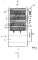
- the elevator 1 has a container 2 for accommodating a plurality of rows 3 of conical bottle capsules 4 inserted one inside the other.
- the respective row 4 is the same length, it consists for example of 150 nested bottle capsules.
- the container 2 has a rectangular base and its two side walls are denoted by the reference numeral 5, the front wall by the reference numeral 6 and the rear wall by the reference numeral 8.
- the interior 7 of the container 2 is used to receive a plurality of rows 3 nested bottle caps 4.
- the length of each row 3 is slightly less than the clear distance between the two side walls 5 of the container 2.
- the rows 3 are filled in the container 2 in that they are positioned with their longitudinal axis substantially parallel to the front wall 6.
- the elevator 1 In the area of the rear wall 8 of the container 2, adjacent to its side walls 5, the elevator 1 has two vertically extending uprights 9. In the region of the upper ends of the stator 9, a drive shaft 10 is mounted in these, which is drivable by means of a flanged to one of the stator 9 electric motor with reduction gear 11. In vertical alignment of the drive shaft 10, a bearing shaft 12 is mounted in the container 2 in the side walls 5 of the container 2. Tilted at an angle of 30 ° to the horizontal, thus below the level of the bearing shaft 12, adjacent to the front wall 6 of the container 2, a further bearing shaft 13 is mounted in the side walls 5 of the container 2. With the drive shaft 10 are, in the region of the two stator 9, two gears 14th rotatably connected to the drive shaft 10.
- two toothed wheels 14 are rotatably mounted in the bearing shafts 12 and 13, respectively, in the region of the two uprights 9.
- the arranged in the region of the sides of the elevator 1 gears 14 wrap around two toothed belt 15.
- a curved from the bevels on the curvature in the vertical plate 22 is provided. In the promotion thus run the strips 16 at a constant distance to the plate 22 over.
- FIG. 4 illustrates how, after the top dead center has been exceeded, a row of 4 bottle capsules inserted into one another is dispensed from the strip 16, which is now conveyed downwards.
- the output takes place on a parallel to the bar 16 arranged conveyor belt 23, which feeds the dispensed row 3 of nested bottle capsules 4 a further processing station.
- Sensors 24 detect the takeover position of the conveyor belt 23 and a discharge position, so that it is ensured that a series 3 nested bottle capsules 4 is only issued from the elevator 1 on the conveyor belt 23, when this area of the conveyor belt is free.
- the elevator 1 is stopped.
- the elevator in turn shows in Area of the vertical conveyor line for the series 3 nested bottle capsules 4 two sensors 25, which determine whether a row 23 nested bottle caps 4 rests on the respective bar 16.
- the power and control cabinet 26 of the elevator 1 is arranged in the region of one side of the container 2.
- the sensors 25 can be detected directly whether the respective formed between adjacent strips 16 chamber 27 is occupied by a series of 3 nested bottle capsules 4.
- some chambers 27 are not occupied (FIGS. 1 and 2).
- the rows 3 nested bottle capsules 4 are given as bulk material.
- a transport container for example, 100, tightly arranged rows 3 loosely inserted into the transport container, thus without the intermediate layer / pallet, as is known from the prior art.
- the transport container is emptied, so that the rows 3 of bottle capsules 4 inserted into one another, as illustrated in FIG. 1, come to lie with their longitudinal axis parallel to the front wall 6 of the container 2. There are therefore a plurality of rows one above the other, the quasi contact the conveyor, the bottom of the container 2.
- the direction of rotation of the conveyor is illustrated by the arrow A.
- the rows 3 nested bottle capsules 4 have the tendency to fall into the chambers 27 formed between adjacent strips 16 and roll in and contact the plate 22.
- This preferably takes place in the region of the conveying means which is adjacent to the bearing shaft 13, thus close to the front wall 6 of the container 2. If the rows 3 do not reach the respective chamber 7 there remains sufficient conveying path of the conveying means to receive the respective row , For example, in the curved area 18. In the worst case, it may well happen that a chamber 27 is left unoccupied, because the bed of rows 3 in the container prevented the row 3 of interest from falling into the chamber.
- This row 3 then slips down, according to the decreasing level of the container 2, until finally, at a later time, it can fall into a free chamber 27 and be conveyed. So that no row 3 can fall into the area below the conveyor, the elevator is designed so that in the lower deflection point, adjacent to the bearing shaft 13, the strip 16 adjacent to the front wall 6 of the container 2 is guided past. The gap 27 formed between the strip 16 and the front wall 6 is dimensioned so small that no row 3 can fall through this gap 28.
- the region 17 of the conveyor is arranged at an angle of 30 ° to the horizontal.
- the chambers 27 extend horizontally.
- the respective chamber 27 is formed by two connected to the timing belt 15 strips 16.
- the distance between adjacent strips is slightly larger than the maximum diameter of the row 3 nested bottle caps 4.
- the extension of the respective chamber 27 in the direction perpendicular to the conveying direction and the chamber longitudinal axis is about as large as the maximum diameter of the rows 3 nested bottle caps 4. Is the diameter larger, the rows 3 protrude slightly beyond the front alignment of the strips out, there is a positive straightening effect in the areas 17 and 18, since the rows located in the chambers act on the other adjacent rows, not yet in a chamber have fallen.
- the respective chamber 27 is bounded by the wall 22.
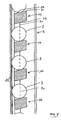
- Figure 5 discloses a detail of the strips 16.
- the surface 29 of the strip 16, with which the row 3 nested bottle capsules 4 contacts, flat and runs, based on the respective chamber 27 at an angle of approximately 70 ° to the conveying plane 30 of the conveyor, said conveyor plane 30th perpendicular to the plane of the sheet as shown in Figure 5 extends.
- the respective bar 16 has a leading outer surface 31, which is arranged perpendicular to the conveying plane of the conveyor. This design requires that over the surface 31, the row 3 in the region of the container 2 can be taken without damage and by means of the surface 29 which is inclined, is secured against rolling out of the chamber 27.
- the respective strip 16 on its side facing away from the surfaces 29 and 31, an outer surface 32 which, based on the respective chamber 27, is arranged at an angle of approximately 100 ° to the conveying plane of the conveyor.
Landscapes
- Engineering & Computer Science (AREA)
- Mechanical Engineering (AREA)
- Branching, Merging, And Special Transfer Between Conveyors (AREA)
- Filling Of Jars Or Cans And Processes For Cleaning And Sealing Jars (AREA)
- Combined Means For Separation Of Solids (AREA)
- Specific Conveyance Elements (AREA)
Claims (21)
- Elévateur (1) pour des articles de série (4) emboîtés les uns dans les autres et disposés en rangées (3), en particulier des capsules de bouteille emboîtées les unes dans les autres,
caractérisé par :- un récipient (2) pour recevoir en vrac une multitude de rangées (3) d'articles de série emboîtés les uns dans les autres (4),- au moins un moyen de convoyage circulaire (15, 16) comprenant une zone de renvoi inférieure (33) située à l'intérieur du récipient (2) et une zone de renvoi supérieure (34) située au-dessus du récipient (2), le moyen de convoyage (15, 16) étant dirigé de façon oblique vers le haut dans toute la zone inférieure (17) sur sa face partant de la zone de renvoi inférieure (33) et tournée vers les rangées (3) d'articles de série emboîtés les uns dans les autres (4), et- des chambres aménagées dans le moyen de convoyage (15, 16), chaque chambre (27) servant à recevoir une rangée (3) d'articles de masse emboîtés les uns dans les autres (4) et étant essentiellement horizontale dans sa direction longitudinale. - Elévateur selon la revendication 1,
la partie (17) du moyen de convoyage (15, 16) dirigée de façon oblique vers le haut étant rectiligne. - Elévateur selon la revendication 2,
la partie oblique (17) du moyen de convoyage (15, 16) étant disposée selon un angle de 20° à 40°, de préférence de 25° à 35°, en particulier de 30° par rapport à l'horizontale. - Elévateur selon l'une quelconque des revendications 1 à 3,
une partie courbée (18) du moyen de convoyage (15, 16), raccordée en haut à la partie (17) dirigée de façon oblique vers le haut du moyen de convoyage (15, 16), étant disposée à l'intérieur du récipient (2). - Elévateur selon la revendication 4,
une partie droite (19) du moyen de convoyage (15, 16), en particulier une partie droite (19) verticale du moyen de convoyage (15, 16) étant raccordée en haut à la partie courbée (18) du moyen de convoyage (15, 16). - Elévateur selon la revendication 5,
la partie droite (19) supérieure du moyen de convoyage (15, 16) étant disposée par son extrémité inférieure à l'intérieur du récipient (2). - Elévateur selon l'une quelconque des revendications 1 à 6,
la longueur de la chambre (27) correspondante et/ou l'étendue de l'espace entouré par le récipient (2), vus dans la direction longitudinale de la chambre (27), étant légèrement supérieures à la longueur de la rangée (3) correspondante d'articles de série (4) emboîtés les uns dans les autres. - Elévateur selon l'une quelconque des revendications 1 à 7,
la zone de renvoi inférieure (33) étant disposée à proximité d'une paroi (6) du récipient (2). - Elévateur selon l'une quelconque des revendications 1 à 8,
la chambre (27) correspondante étant disposée horizontalement au niveau de sa direction longitudinale. - Elévateur selon l'une quelconque des revendications 1 à 9,
la chambre correspondante étant délimitée, dans la direction de convoyage, par deux barrettes. - Elévateur selon la revendication 10,
la distance entre des barrettes voisines (16) étant légèrement supérieure au diamètre maximal de la rangée (3) d'articles de série emboîtés les uns dans les autres (4). - Elévateur selon l'une quelconque des revendications 1 à 11, l'étendue de la chambre (27) correspondante étant sensiblement équivalente au diamètre maximal de la rangée (3) d'articles de série emboîtés les uns dans les autres (4) dans la direction perpendiculaire à la direction de convoyage (30) et à l'axe longitudinal de la chambre.
- Elévateur selon l'une quelconque des revendications 10 à 12,
dans lequel la surface (29) de la barrette (16) en contact avec la rangée (3) d'articles de masse emboîtés les uns dans les autres (4), est plane et/ou ou disposée, par rapport à la chambre correspondante, selon un angle de 65° à 85°, en particulier de 70° par rapport au plan de convoyage du moyen de convoyage (15, 16). - Elévateur selon la revendication 13,
dans lequel la barrette (16) présentant une surface extérieure (31) avant est perpendiculaire au plan de convoyage du moyen de convoyage (15, 16). - Elévateur selon l'une quelconque des revendications 10 à 14,
dans lequel la barrette (16), sur son côté opposée la surface (29) qui entre en contact avec la rangée (3) d'articles de série emboîtés les uns dans les autres (4), présente une surface (32) qui, rapporté à la chambre correspondante (27), fait un angle de 95° à 105°, en particulier de 100° avec le plan de convoyage du moyen de convoyage (15, 16). - Elévateur selon l'une quelconque des revendications 1 à 15,
les moyens de convoyage (15, 16) présentant des courroies dentées (15) ou des chaînes auxquelles sont fixées les baguettes (16). - Elévateur selon l'une quelconque des revendications 1 à 16,
caractérisé en ce que
dans la direction du convoyage, la chambre correspondante (27) est délimitée par des baguettes (16) tournées vers celle-ci, et à l'arrière par une paroi (22) disposée parallèlement à la direction de transport du moyen de convoyage (15, 16). - Elévateur selon l'une quelconque des revendications 1 à 17,
avec dans la zone de renvoi supérieure (34) du moyen de convoyage (15, 16), un convoyeur (23) ou un magasin pour recevoir les rangées (3) d'articles de série emboîtés les uns dans les autres (4). - Elévateur selon l'une quelconque des revendications 1 à 18,
des capteurs (23, 24) étant prévus pour détecter l'occupation des chambres correspondantes (27) et/ou l'occupation du convoyeur d'évacuation (23) et/ou l'occupation du magasin. - Procédé de séparation des rangées (3) d'articles de série emboîtés les uns dans les autres (4) et disposés en rangées, en particulier de capsules de bouteille emboîtées les unes dans les autres, comprenant les étapes suivantes :- prévoir un élévateur selon l'une quelconque des revendications 1 à 19,- transférer en vrac les rangées (3) dans le récipient (2) pour la réception en vrac d'une multitude de rangées (3),- séparer la multitude des rangées (3) situées dans le récipient (2) au moyen de la partie (17) du moyen de convoyage (15, 16) dirigée vers le haut,- convoyer les rangées (3) séparées vers une station de traitement ultérieur.
- Procédé selon la revendication 20, 1
le transfert en vrac des rangées (3) d'articles de série emboîtés les uns dans les autres (4) dans un récipient (2) étant réalisé par installation dans le récipient (2) des rangées (3) juxtaposées dans un récipient de transport.
Priority Applications (4)
| Application Number | Priority Date | Filing Date | Title |
|---|---|---|---|
| EP03028463A EP1541504B1 (fr) | 2003-12-12 | 2003-12-12 | Convoyeur élévateur pour la séparation des articles de série, particulièrement des piles de capsules de bouteille, et procédure correspondante |
| DE50303866T DE50303866D1 (de) | 2003-12-12 | 2003-12-12 | Steilförderer zum Vereinzeln von Massenartikeln, insbesondere Stapel von Flaschenkapseln, sowie entsprechendes Verfahren |
| ES03028463T ES2266710T3 (es) | 2003-12-12 | 2003-12-12 | Transportador elevador para la separacion de articulos de serie, espe cialmente de pilas de caperuzas de botellas, asi como procedimiento correspondiente. |
| AT03028463T ATE329864T1 (de) | 2003-12-12 | 2003-12-12 | Steilförderer zum vereinzeln von massenartikeln, insbesondere stapel von flaschenkapseln, sowie entsprechendes verfahren |
Applications Claiming Priority (1)
| Application Number | Priority Date | Filing Date | Title |
|---|---|---|---|
| EP03028463A EP1541504B1 (fr) | 2003-12-12 | 2003-12-12 | Convoyeur élévateur pour la séparation des articles de série, particulièrement des piles de capsules de bouteille, et procédure correspondante |
Publications (2)
| Publication Number | Publication Date |
|---|---|
| EP1541504A1 EP1541504A1 (fr) | 2005-06-15 |
| EP1541504B1 true EP1541504B1 (fr) | 2006-06-14 |
Family
ID=34486182
Family Applications (1)
| Application Number | Title | Priority Date | Filing Date |
|---|---|---|---|
| EP03028463A Expired - Lifetime EP1541504B1 (fr) | 2003-12-12 | 2003-12-12 | Convoyeur élévateur pour la séparation des articles de série, particulièrement des piles de capsules de bouteille, et procédure correspondante |
Country Status (4)
| Country | Link |
|---|---|
| EP (1) | EP1541504B1 (fr) |
| AT (1) | ATE329864T1 (fr) |
| DE (1) | DE50303866D1 (fr) |
| ES (1) | ES2266710T3 (fr) |
Cited By (1)
| Publication number | Priority date | Publication date | Assignee | Title |
|---|---|---|---|---|
| US9376301B1 (en) | 2015-07-16 | 2016-06-28 | Jalbert Automatisation Inc. | Adjustable cap sorter |
Families Citing this family (8)
| Publication number | Priority date | Publication date | Assignee | Title |
|---|---|---|---|---|
| AT507740B1 (de) * | 2008-07-16 | 2021-07-15 | Gassner Gmbh | Sortiergerät |
| CN104139963B (zh) * | 2013-05-07 | 2017-02-22 | 广东隆兴包装实业有限公司 | 圆柱形曲面印刷机的自动提升送料装置 |
| CN104648965B (zh) * | 2015-01-07 | 2017-03-08 | 于振中 | 一种提升对夹上料机 |
| CN106429158B (zh) * | 2016-08-31 | 2024-03-19 | 上海三禾服装物流设备制造有限公司 | 垂直投送系统 |
| CN110562510A (zh) * | 2019-09-17 | 2019-12-13 | 赖进九 | 一种压铸件包装设备 |
| CN112518405A (zh) * | 2020-11-23 | 2021-03-19 | 浙江冠利新材料股份有限公司 | 一种铝制瓶盖进料机构 |
| CN113633013B (zh) * | 2021-09-09 | 2022-05-31 | 江西中烟工业有限责任公司 | 一种适用于切梗丝机设备的烟梗定向排列喂料装置 |
| CN114195065B (zh) * | 2021-11-25 | 2024-02-20 | 长三角(义乌)生态环境研究中心 | 一种用于改性水处理试剂的制备系统及其工作方法 |
Family Cites Families (2)
| Publication number | Priority date | Publication date | Assignee | Title |
|---|---|---|---|---|
| DE3629561A1 (de) * | 1986-08-30 | 1988-03-03 | Schlafhorst & Co W | Vorrichtung zum konstanthalten der anzahl der zwischen einer spinnmaschine und einer spulmaschine in einem kreislauf befindlichen spulenhuelsen |
| AT3964U1 (de) * | 1999-10-19 | 2000-11-27 | Gassner Gmbh | Sortiergerät |
-
2003
- 2003-12-12 AT AT03028463T patent/ATE329864T1/de not_active IP Right Cessation
- 2003-12-12 EP EP03028463A patent/EP1541504B1/fr not_active Expired - Lifetime
- 2003-12-12 DE DE50303866T patent/DE50303866D1/de not_active Expired - Fee Related
- 2003-12-12 ES ES03028463T patent/ES2266710T3/es not_active Expired - Lifetime
Cited By (1)
| Publication number | Priority date | Publication date | Assignee | Title |
|---|---|---|---|---|
| US9376301B1 (en) | 2015-07-16 | 2016-06-28 | Jalbert Automatisation Inc. | Adjustable cap sorter |
Also Published As
| Publication number | Publication date |
|---|---|
| DE50303866D1 (de) | 2006-07-27 |
| EP1541504A1 (fr) | 2005-06-15 |
| ATE329864T1 (de) | 2006-07-15 |
| ES2266710T3 (es) | 2007-03-01 |
Similar Documents
| Publication | Publication Date | Title |
|---|---|---|
| EP3115322B1 (fr) | Procede et dispositif destines a la depalettisation de pneus | |
| EP2332865B1 (fr) | Dispositif de palettisation et/ou de dépalettisation | |
| DE69008458T2 (de) | Verfahren und Apparat für die Puffersteuerung in Fördersystemen. | |
| EP2585375B1 (fr) | Machine pour transporter une pile de boites a oeufs ouvertes, ainsi qu' un appareil de separation des boites et un dispositif d'empilage des boites videes | |
| EP2874926B1 (fr) | Procede et dispositif de chargement d'une palette | |
| EP2128047B2 (fr) | Dispositif de réception pour un véhicule transporteur | |
| EP2635510A1 (fr) | Dispositif de transport pour le transport de conteneurs | |
| EP1541504B1 (fr) | Convoyeur élévateur pour la séparation des articles de série, particulièrement des piles de capsules de bouteille, et procédure correspondante | |
| EP2412632B1 (fr) | Machine d'emballage par emboutissage et procédé de remplissage de barquettes d'emballage avec des produits | |
| EP0538742B1 (fr) | Entrepôt pour pièces de marchandises | |
| EP0930257B1 (fr) | Procédé et dispositif pour empiler des tranches non-emballées de fromage fondu | |
| DE102017113410A1 (de) | Umsetzvorrichtung zur Umsetzung von Eiern und Vorrichtung zum Transport und Verpacken von Eiern | |
| EP0713835B1 (fr) | Dispositif de palettisation | |
| DE69607698T2 (de) | Vorrichtung zum Be- und/oder Entladen von einem Behälter mit Stapeln von Packungen, insbesondere Eierkartons | |
| EP2176149B1 (fr) | Procédé de désempilement ou d'empilement de fûts | |
| DE4102654C2 (de) | Be- und Entladevorrichtung | |
| CH673818A5 (fr) | ||
| CH681590A5 (fr) | ||
| EP0416627B1 (fr) | Procédé et dispositif pour stocker et reprendre automatiquement des sortes de marchandises de détail de rayonnages dans de grands entrepôts | |
| EP1652799B1 (fr) | Dispositif pour individualiser des marchandises | |
| DE4124703C2 (de) | Palettenbeladeplatz zum schichtenweisen ablegen von behaeltern, insbesondere flaschenkaesten, auf eine palette | |
| EP0697356A1 (fr) | Dispositif pour empiler ou désempiler des marchandises superposables | |
| CH664710A5 (en) | Sorting wooden planks according to size or quality - using sensors to control endless belts for storing and transporting planks | |
| DE2716296A1 (de) | Vorrichtung zum weiterfoerdern der beim abraeumen von getraenkebehaeltnissen anfallenden zwischenlagen | |
| DE3327953A1 (de) | Sackvereinzelungsvorrichtung zur aufloesung eines aus einzelgebinden gebildeten haufwerkes, sowie ein ergaenzendes verfahren |
Legal Events
| Date | Code | Title | Description |
|---|---|---|---|
| PUAI | Public reference made under article 153(3) epc to a published international application that has entered the european phase |
Free format text: ORIGINAL CODE: 0009012 |
|
| 17P | Request for examination filed |
Effective date: 20050310 |
|
| AK | Designated contracting states |
Kind code of ref document: A1 Designated state(s): AT BE BG CH CY CZ DE DK EE ES FI FR GB GR HU IE IT LI LU MC NL PT RO SE SI SK TR |
|
| AX | Request for extension of the european patent |
Extension state: AL LT LV MK |
|
| 17Q | First examination report despatched |
Effective date: 20050624 |
|
| GRAP | Despatch of communication of intention to grant a patent |
Free format text: ORIGINAL CODE: EPIDOSNIGR1 |
|
| AKX | Designation fees paid |
Designated state(s): AT BE BG CH CY CZ DE DK EE ES FI FR GB GR HU IE IT LI LU MC NL PT RO SE SI SK TR |
|
| GRAS | Grant fee paid |
Free format text: ORIGINAL CODE: EPIDOSNIGR3 |
|
| GRAA | (expected) grant |
Free format text: ORIGINAL CODE: 0009210 |
|
| AK | Designated contracting states |
Kind code of ref document: B1 Designated state(s): AT BE BG CH CY CZ DE DK EE ES FI FR GB GR HU IE IT LI LU MC NL PT RO SE SI SK TR |
|
| PG25 | Lapsed in a contracting state [announced via postgrant information from national office to epo] |
Ref country code: CZ Free format text: LAPSE BECAUSE OF FAILURE TO SUBMIT A TRANSLATION OF THE DESCRIPTION OR TO PAY THE FEE WITHIN THE PRESCRIBED TIME-LIMIT Effective date: 20060614 Ref country code: IE Free format text: LAPSE BECAUSE OF FAILURE TO SUBMIT A TRANSLATION OF THE DESCRIPTION OR TO PAY THE FEE WITHIN THE PRESCRIBED TIME-LIMIT Effective date: 20060614 Ref country code: RO Free format text: LAPSE BECAUSE OF FAILURE TO SUBMIT A TRANSLATION OF THE DESCRIPTION OR TO PAY THE FEE WITHIN THE PRESCRIBED TIME-LIMIT Effective date: 20060614 Ref country code: GB Free format text: LAPSE BECAUSE OF FAILURE TO SUBMIT A TRANSLATION OF THE DESCRIPTION OR TO PAY THE FEE WITHIN THE PRESCRIBED TIME-LIMIT Effective date: 20060614 Ref country code: SK Free format text: LAPSE BECAUSE OF FAILURE TO SUBMIT A TRANSLATION OF THE DESCRIPTION OR TO PAY THE FEE WITHIN THE PRESCRIBED TIME-LIMIT Effective date: 20060614 Ref country code: FI Free format text: LAPSE BECAUSE OF FAILURE TO SUBMIT A TRANSLATION OF THE DESCRIPTION OR TO PAY THE FEE WITHIN THE PRESCRIBED TIME-LIMIT Effective date: 20060614 Ref country code: SI Free format text: LAPSE BECAUSE OF FAILURE TO SUBMIT A TRANSLATION OF THE DESCRIPTION OR TO PAY THE FEE WITHIN THE PRESCRIBED TIME-LIMIT Effective date: 20060614 Ref country code: NL Free format text: LAPSE BECAUSE OF FAILURE TO SUBMIT A TRANSLATION OF THE DESCRIPTION OR TO PAY THE FEE WITHIN THE PRESCRIBED TIME-LIMIT Effective date: 20060614 |
|
| REG | Reference to a national code |
Ref country code: GB Ref legal event code: FG4D Free format text: NOT ENGLISH |
|
| REG | Reference to a national code |
Ref country code: CH Ref legal event code: EP |
|
| REG | Reference to a national code |
Ref country code: IE Ref legal event code: FG4D Free format text: LANGUAGE OF EP DOCUMENT: GERMAN |
|
| REF | Corresponds to: |
Ref document number: 50303866 Country of ref document: DE Date of ref document: 20060727 Kind code of ref document: P |
|
| PG25 | Lapsed in a contracting state [announced via postgrant information from national office to epo] |
Ref country code: DK Free format text: LAPSE BECAUSE OF FAILURE TO SUBMIT A TRANSLATION OF THE DESCRIPTION OR TO PAY THE FEE WITHIN THE PRESCRIBED TIME-LIMIT Effective date: 20060914 Ref country code: SE Free format text: LAPSE BECAUSE OF FAILURE TO SUBMIT A TRANSLATION OF THE DESCRIPTION OR TO PAY THE FEE WITHIN THE PRESCRIBED TIME-LIMIT Effective date: 20060914 |
|
| PG25 | Lapsed in a contracting state [announced via postgrant information from national office to epo] |
Ref country code: PT Free format text: LAPSE BECAUSE OF FAILURE TO SUBMIT A TRANSLATION OF THE DESCRIPTION OR TO PAY THE FEE WITHIN THE PRESCRIBED TIME-LIMIT Effective date: 20061114 |
|
| NLV1 | Nl: lapsed or annulled due to failure to fulfill the requirements of art. 29p and 29m of the patents act | ||
| PG25 | Lapsed in a contracting state [announced via postgrant information from national office to epo] |
Ref country code: BE Free format text: LAPSE BECAUSE OF NON-PAYMENT OF DUE FEES Effective date: 20061231 Ref country code: MC Free format text: LAPSE BECAUSE OF NON-PAYMENT OF DUE FEES Effective date: 20061231 |
|
| GBV | Gb: ep patent (uk) treated as always having been void in accordance with gb section 77(7)/1977 [no translation filed] |
Effective date: 20060614 |
|
| REG | Reference to a national code |
Ref country code: IE Ref legal event code: FD4D |
|
| ET | Fr: translation filed | ||
| REG | Reference to a national code |
Ref country code: ES Ref legal event code: FG2A Ref document number: 2266710 Country of ref document: ES Kind code of ref document: T3 |
|
| PLBE | No opposition filed within time limit |
Free format text: ORIGINAL CODE: 0009261 |
|
| STAA | Information on the status of an ep patent application or granted ep patent |
Free format text: STATUS: NO OPPOSITION FILED WITHIN TIME LIMIT |
|
| 26N | No opposition filed |
Effective date: 20070315 |
|
| BERE | Be: lapsed |
Owner name: DRAHT- UND METALLWARENFABRIK PHILIPP SCHNEIDER G. Effective date: 20061231 |
|
| PG25 | Lapsed in a contracting state [announced via postgrant information from national office to epo] |
Ref country code: AT Free format text: LAPSE BECAUSE OF NON-PAYMENT OF DUE FEES Effective date: 20061212 |
|
| PG25 | Lapsed in a contracting state [announced via postgrant information from national office to epo] |
Ref country code: GR Free format text: LAPSE BECAUSE OF FAILURE TO SUBMIT A TRANSLATION OF THE DESCRIPTION OR TO PAY THE FEE WITHIN THE PRESCRIBED TIME-LIMIT Effective date: 20060915 |
|
| PG25 | Lapsed in a contracting state [announced via postgrant information from national office to epo] |
Ref country code: EE Free format text: LAPSE BECAUSE OF FAILURE TO SUBMIT A TRANSLATION OF THE DESCRIPTION OR TO PAY THE FEE WITHIN THE PRESCRIBED TIME-LIMIT Effective date: 20060614 Ref country code: BG Free format text: LAPSE BECAUSE OF FAILURE TO SUBMIT A TRANSLATION OF THE DESCRIPTION OR TO PAY THE FEE WITHIN THE PRESCRIBED TIME-LIMIT Effective date: 20060914 |
|
| PG25 | Lapsed in a contracting state [announced via postgrant information from national office to epo] |
Ref country code: LU Free format text: LAPSE BECAUSE OF NON-PAYMENT OF DUE FEES Effective date: 20061212 Ref country code: TR Free format text: LAPSE BECAUSE OF FAILURE TO SUBMIT A TRANSLATION OF THE DESCRIPTION OR TO PAY THE FEE WITHIN THE PRESCRIBED TIME-LIMIT Effective date: 20060614 Ref country code: HU Free format text: LAPSE BECAUSE OF FAILURE TO SUBMIT A TRANSLATION OF THE DESCRIPTION OR TO PAY THE FEE WITHIN THE PRESCRIBED TIME-LIMIT Effective date: 20061215 |
|
| REG | Reference to a national code |
Ref country code: CH Ref legal event code: PL |
|
| PG25 | Lapsed in a contracting state [announced via postgrant information from national office to epo] |
Ref country code: LI Free format text: LAPSE BECAUSE OF NON-PAYMENT OF DUE FEES Effective date: 20071231 Ref country code: CH Free format text: LAPSE BECAUSE OF NON-PAYMENT OF DUE FEES Effective date: 20071231 |
|
| PG25 | Lapsed in a contracting state [announced via postgrant information from national office to epo] |
Ref country code: CY Free format text: LAPSE BECAUSE OF FAILURE TO SUBMIT A TRANSLATION OF THE DESCRIPTION OR TO PAY THE FEE WITHIN THE PRESCRIBED TIME-LIMIT Effective date: 20060614 |
|
| PGFP | Annual fee paid to national office [announced via postgrant information from national office to epo] |
Ref country code: ES Payment date: 20081217 Year of fee payment: 6 |
|
| PGFP | Annual fee paid to national office [announced via postgrant information from national office to epo] |
Ref country code: IT Payment date: 20081222 Year of fee payment: 6 |
|
| PGFP | Annual fee paid to national office [announced via postgrant information from national office to epo] |
Ref country code: FR Payment date: 20081212 Year of fee payment: 6 |
|
| PGFP | Annual fee paid to national office [announced via postgrant information from national office to epo] |
Ref country code: DE Payment date: 20081218 Year of fee payment: 6 |
|
| REG | Reference to a national code |
Ref country code: FR Ref legal event code: ST Effective date: 20100831 |
|
| PG25 | Lapsed in a contracting state [announced via postgrant information from national office to epo] |
Ref country code: FR Free format text: LAPSE BECAUSE OF NON-PAYMENT OF DUE FEES Effective date: 20091231 |
|
| PG25 | Lapsed in a contracting state [announced via postgrant information from national office to epo] |
Ref country code: DE Free format text: LAPSE BECAUSE OF NON-PAYMENT OF DUE FEES Effective date: 20100701 |
|
| REG | Reference to a national code |
Ref country code: ES Ref legal event code: FD2A Effective date: 20110307 |
|
| PG25 | Lapsed in a contracting state [announced via postgrant information from national office to epo] |
Ref country code: IT Free format text: LAPSE BECAUSE OF NON-PAYMENT OF DUE FEES Effective date: 20091212 |
|
| PG25 | Lapsed in a contracting state [announced via postgrant information from national office to epo] |
Ref country code: ES Free format text: LAPSE BECAUSE OF NON-PAYMENT OF DUE FEES Effective date: 20110304 |
|
| PG25 | Lapsed in a contracting state [announced via postgrant information from national office to epo] |
Ref country code: ES Free format text: LAPSE BECAUSE OF NON-PAYMENT OF DUE FEES Effective date: 20091213 |