EP1541296A1 - Manipulateur, comme un robot industriel, avec enceintes de rinçage, et procédé pour influencer un parametre ambiant dans un tel manipulateur - Google Patents
Manipulateur, comme un robot industriel, avec enceintes de rinçage, et procédé pour influencer un parametre ambiant dans un tel manipulateur Download PDFInfo
- Publication number
- EP1541296A1 EP1541296A1 EP04028506A EP04028506A EP1541296A1 EP 1541296 A1 EP1541296 A1 EP 1541296A1 EP 04028506 A EP04028506 A EP 04028506A EP 04028506 A EP04028506 A EP 04028506A EP 1541296 A1 EP1541296 A1 EP 1541296A1
- Authority
- EP
- European Patent Office
- Prior art keywords
- handling device
- flushing medium
- flushing
- washing compartment
- medium
- Prior art date
- Legal status (The legal status is an assumption and is not a legal conclusion. Google has not performed a legal analysis and makes no representation as to the accuracy of the status listed.)
- Granted
Links
Images
Classifications
-
- B—PERFORMING OPERATIONS; TRANSPORTING
- B25—HAND TOOLS; PORTABLE POWER-DRIVEN TOOLS; MANIPULATORS
- B25J—MANIPULATORS; CHAMBERS PROVIDED WITH MANIPULATION DEVICES
- B25J19/00—Accessories fitted to manipulators, e.g. for monitoring, for viewing; Safety devices combined with or specially adapted for use in connection with manipulators
- B25J19/0054—Cooling means
-
- B—PERFORMING OPERATIONS; TRANSPORTING
- B25—HAND TOOLS; PORTABLE POWER-DRIVEN TOOLS; MANIPULATORS
- B25J—MANIPULATORS; CHAMBERS PROVIDED WITH MANIPULATION DEVICES
- B25J19/00—Accessories fitted to manipulators, e.g. for monitoring, for viewing; Safety devices combined with or specially adapted for use in connection with manipulators
- B25J19/0075—Means for protecting the manipulator from its environment or vice versa
- B25J19/0079—Means for protecting the manipulator from its environment or vice versa using an internal pressure system
-
- B—PERFORMING OPERATIONS; TRANSPORTING
- B65—CONVEYING; PACKING; STORING; HANDLING THIN OR FILAMENTARY MATERIAL
- B65G—TRANSPORT OR STORAGE DEVICES, e.g. CONVEYORS FOR LOADING OR TIPPING, SHOP CONVEYOR SYSTEMS OR PNEUMATIC TUBE CONVEYORS
- B65G2249/00—Aspects relating to conveying systems for the manufacture of fragile sheets
- B65G2249/02—Controlled or contamination-free environments or clean space conditions
-
- Y—GENERAL TAGGING OF NEW TECHNOLOGICAL DEVELOPMENTS; GENERAL TAGGING OF CROSS-SECTIONAL TECHNOLOGIES SPANNING OVER SEVERAL SECTIONS OF THE IPC; TECHNICAL SUBJECTS COVERED BY FORMER USPC CROSS-REFERENCE ART COLLECTIONS [XRACs] AND DIGESTS
- Y10—TECHNICAL SUBJECTS COVERED BY FORMER USPC
- Y10T—TECHNICAL SUBJECTS COVERED BY FORMER US CLASSIFICATION
- Y10T74/00—Machine element or mechanism
- Y10T74/20—Control lever and linkage systems
- Y10T74/20207—Multiple controlling elements for single controlled element
- Y10T74/20305—Robotic arm
- Y10T74/20311—Robotic arm including power cable or connector
-
- Y—GENERAL TAGGING OF NEW TECHNOLOGICAL DEVELOPMENTS; GENERAL TAGGING OF CROSS-SECTIONAL TECHNOLOGIES SPANNING OVER SEVERAL SECTIONS OF THE IPC; TECHNICAL SUBJECTS COVERED BY FORMER USPC CROSS-REFERENCE ART COLLECTIONS [XRACs] AND DIGESTS
- Y10—TECHNICAL SUBJECTS COVERED BY FORMER USPC
- Y10T—TECHNICAL SUBJECTS COVERED BY FORMER US CLASSIFICATION
- Y10T74/00—Machine element or mechanism
- Y10T74/20—Control lever and linkage systems
- Y10T74/20207—Multiple controlling elements for single controlled element
- Y10T74/20305—Robotic arm
- Y10T74/20329—Joint between elements
Definitions
- the invention relates to a method for influencing at least an environmental condition, such as temperature, humidity, Pressure, pollution and / or germ load, in the area of drive units of the handling device, such as a multi-axis industrial robot. Furthermore, the concerns Invention a handling device, such as multi-axis industrial robots, especially for use in contaminated Environment, with a number of with a flushing medium acted upon washrooms in the range of drive units of the handling device.
- an environmental condition such as temperature, humidity, Pressure, pollution and / or germ load
- Robot in particular in an automated form as Multi-axis industrial robot, hereafter referred to as robot designated, found today in many fields of the Technique use. It is in a use of such Robots in a contaminated environment, such as the Food processing industry or the pharmaceutical industry, to strictly pay attention, no applicable hygiene regulations by release of abrasive particles and / or To violate lubricant vapors.
- a source for such Contaminations are especially the joint areas of the Robot, in which the drive units for the moving Parts of the robot with their engines and various relative mutually moving components are arranged, what about it on the one hand the presence of lubricants and on the other hand, open interfaces in the robot structure conditionally, so it in these places especially in consequence of friction effects to the mentioned contamination effects comes.
- WO 00/29177 proposes the entirety of the drive means of a robot with To surround a pressure-tight housing and in this for cooling purposes for a closed flow of a cooling gas to care.
- EP 0 203 202 A1 shows an industrial robot, in its interior a coherent, with a pressure medium acted upon washroom for the drive units provided is.
- the subject of EP 0 245 530 A1 is a motor means for a robot hand in one with a print medium arranged acted panel arranged; at the object DE 36 27 775 A1 are drive units of an industrial robot arranged in individual, airtight containers, be introduced into the compressed air as inert gas can.
- the invention is based on the object, a method and a handling device of the type mentioned in the effect develop further, that a safe use of the Handling device in a contaminated environment in structurally simpler and thus more cost-effective Way is possible.
- the object is in a method of the aforementioned Kind solved thereby, that a plurality of for each one Group of drive units provided with Spülsammlung a flushing medium to be applied.
- a handling device of the type mentioned is to solve the Task provided that a plurality of groups of drive units each assigned its own dishwasher is. This is according to the invention to simple and flexible usable manner for a Einsetzfind the Handling device especially in contaminated Environment taken care of.
- the washing compartment is pressurized and a preferred Embodiment of the handling device according to the invention, that the rinsing rooms are pressurized.
- the detergent is So in the washrooms with a, if appropriate only very little overpressure introduced, that is they are definitely rinsed with the gaseous rinse, the is blown into the sinks and forming over resistors Outlets is drained, so that according to this embodiment in the washrooms always at least a little Overpressure is maintained.
- a development of the method according to the invention sees before, that supplying and / or removing the flushing medium is controlled separately for each washroom, resulting in a further increase the versatility of the robot leads. Accordingly, according to a development of the invention Handling device, a pressure of the flushing medium in each washroom separately controllable.
- the method according to the invention can be used to targeted to environmental conditions in the range of drive units to act on a handling device.
- To reach a cooling effect provides a highly preferred development of the inventive method that the Rinsing medium at least after flowing through a washing compartment is cooled.
- the flushing medium at least after a flow through a washing compartment is dried.
- the flushing medium at least is filtered after flowing through a washing compartment.
- a training of contamination herds like bacteria nests, to prevent, looks a very utterly preferred development of the method according to the invention before that the flushing medium before flowing through a flushing chamber is added in a disinfectant.
- the Rinsing medium after flowing through one of the rinsing rooms either delivered to the environment or the washroom again is supplied.
- Corresponding developments of the invention Handling device provide that supply and AbGermanschläuche for at least one washing compartment a closed Form a cycle or at least one A medium drained space can be delivered to the environment is.
- the flushing medium in at least one washing compartment in a defined flow movement is offset.
- the flushing medium at least one flushing room with one opposite one Ambient pressure increased pressure supplied. It can, however also be useful, the flushing medium at least one washing compartment with a reduced relative to an ambient pressure To supply pressure, or to suck through the washrooms, for example if targeted leakage of substances the robot should be avoided in the environment.
- the Rinsing medium via externally arranged on the handling device Hoses to be added and / or discharged.
- the handling device Preferably is a number of supply and / or discharge hoses together with a cable arrangement for supply and control the drive units laid, wherein in extremely preferred Development of the subject invention, the flushing medium over a protective tube of the cable assembly is dischargeable.
- the pressure of the flushing medium in at least a flushing chamber above an ambient pressure or in at least a washing compartment below the ambient pressure lies.
- an overpressure is preferably 0.1-1.0 bar.
- a defined flow movement in the washrooms provides a preferred Embodiment of the handling device according to the invention, that at least one washing compartment inlet means or deflection means for influencing a flow of the flushing medium.
- a pressure medium comes from handling reasons preferably a gas or gas mixture and in highly preferred Design in at least one flushing air to Commitment.
- a gas or gas mixture in highly preferred Design in at least one flushing air to Commitment.
- an inert gas as a flushing medium in at least one Washing room possible and provided.
- the flushing medium beyond in at least one washing compartment contain disinfecting substances.
- At least one washroom for the corresponding drive units in the region of a rotation axis a carousel and the pivot axis of a swingarm a six-axis industrial robot is arranged.
- at least one washing compartment for the corresponding drive units a robot arm or a robot hand in Range of the pivot axis of the robot arm of a six-axis industrial robot be arranged.
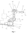
- FIG. 1 shows a side view of an inventive handling device in the form of a multi-axis industrial robot 1.
- This comprises a base frame 1.1, a carousel 1.2, a rocker 1.3, a robot arm 1.4 and a robot hand 1.5, wherein the individual parts 1.1-1.5 of Robot 1 and possibly their other sub-components relative to each other pivotal or rotational movements about axes A 1 -A 6 can perform.
- the robot 1 For power supply and control of its drive units, the robot 1 partially externally along its structure laid cable packages (not visible) which are surrounded in particular for protection against mechanical damage of a protective tube 1.6.
- hoses 1.7a, 1.7b for a flushing medium are provided outside the structure of the robot 1 and at least partially laid together with the protective tube 1.6.
- the robot 1 has in the illustrated embodiment in Basic Frame Carousel Swingarm and Swingarm Arm Hand two flushing rooms 1.8a, 1.8b on which the engines and Transmission (drive units) of the axes A1 and A2 or the Axis A3 and the hand axes A4-A6 include.
- the washrooms 1.8a, 1.8b are about the hoses 1.7a and 1.7b with a Rinsing medium, for example for cooling, drying or disinfection purposes, acted upon.
- the handling device according to the invention has a Conditioning device 2 for the flushing medium, the will be described in detail below with reference to FIG. 2.
- the treatment device 2 is preferably according to the invention outside a contaminated area (Hygiene area) in which the robot 1 is located.
- the flushing chambers 1.8a, 1.8b are sealed tight according to the invention and have for this purpose in particular covers 1.8a ', 1.8b', with appropriately suitable sealants (not shown here) are provided.
- the removal of the flushing medium from the washing rooms 1.8 a, 1.8 b takes place in the robot 1 of FIG. 1 on the protective tube 1.6.
- additional discharge hoses analogous to the hoses 1.7a, 1.7b for discharging be provided of the flushing medium.
- the Conditioning device 2 can be the washing rooms 1.8 a, 1.8 b of the robot 1 partially with opposite an ambient pressure increased (over pressure) or decreased Apply pressure (negative pressure), the latter Alternative interesting especially for cleanroom applications is.
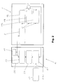
- Fig. 2 shows by means of a block diagram again the inventive handling device 1 of FIG. 1 together with the treatment device 2 for the flushing medium.
- the processing device 2 has a drying device 2.1, a compressor device 2.2 as well a tempering device 2.3, for example a cooling device, on.
- the drying device 2.1 is according to the invention via a supply line 2.1a with a flushing medium reservoir 2.4, when using air as a flushing medium so For example, with the ambient air, connected.
- the processing device 2 still has a feeding device 2.5 for a disinfectant and a filter device 2.6 for filtering out particles, such as abrasive particles, from the rinsing medium.
- the robot 1 can basically according to the illustration of Fig. 2 next to the rinsing rooms already shown in Fig. 1 1.8a, 1.8b still have additional rinse 1.8c. These be inventively via a preferably within the Robot arranged pressure control / distribution device 3 with supplied to the flushing medium.
- a preferably within the Robot arranged pressure control / distribution device 3 with supplied to the flushing medium.
- the flow path of the Rinsing medium indicated in Fig. 2 by arrows.
- an inert gas e.g. Nitrogen
- a disinfectant possible.
- the flushing medium is the robot 1 according to the embodiment 2 fed by the compressor 2.2 with overpressure. If the flushing medium is too moist and / or too warm is to the possible tasks of drying and / or To sufficiently satisfy cooling, the feed must be Rinsing medium previously appropriately tempered and dried become. This happens within the processing facility by the drying device 2.1 or the Tempering device (cooling device) 2.3. That's it irrelevant if the flushing medium in an open circuit or a closed circuit - as shown in Fig. 2 - flows.
- FIG. 2 can flush the medium after one or more times the flushing rooms 1.8a-1.8c are delivered to the environment, preferably when the flushing medium is air, or after a treatment in the treatment device 2 again be routed to the robot 1.
- flushing medium flow can be advantageously for cooling drive units of the robot 1, since in these particular by the encapsulation the heat dissipation necessary during operation only very limited possible.
- condensation will dissipated by a dry flushing medium, the heating This process is still supported by the engines and transmissions.
- the flushing medium but also in quiet phases of the robot to flow, even then to prevent condensation. Continue lets through a defined overpressure in the interior of the washrooms the robot's penetration of dirt and spray, especially during a cleaning phase, by effectively supporting sealants, such as sealing lips or the like.
- a preferred measure here Overpressures in the range of 0.1-0.5 bar.
- the pressure in the Washrooms for further support of the To increase seals significantly, thus a high-pressure jet a cleaning device, the seals of the washrooms not can infiltrate.
- Technically sensible values for overpressure lie in the range of 0.5-1 bar.
- a danger The damage of seals is here in principle excluded because the robot axes during a cleaning usually not or only very slowly become.
- the pressure control / distributor 3 is used according to the invention for controlling a quantity of the flushing medium in the washing rooms 1.8b-1.8c by limiting an internal pressure in these spaces.
- the total volume of flushing medium introduced then results from the by the compressor means 2.2 applied pressure and a flow resistance in the Outlet line 1.6 for the flushing medium.
- the Pressure and the flushing medium volume in addition by further Influencing means (not shown), such as a throttle in the exhaust duct, to influence. If additional to the compressor means 2.2 in the treatment device 2 still provides a suitable pumping means (not shown) is, the flushing medium in case of high flow resistance be sucked targeted in the discharge line.
- Negative pressures in the area of the washing chambers 1.8a-1.8c can be generated. If in a training of the subject matter of FIG. 2 for each flushing space 1.8a, 1.8b, 1.8c a separate pressure regulating and distributing device 3 is used, the amount of flushing medium can different positions as needed separately dosed become.
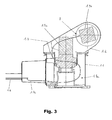
- Rinsing concept is a defined Flow of the flushing medium within the flushing chambers (1.8a-1.8c). This is inventively designed so that they both a discharge of moisture as well as for cooling purposes suitable is. The flow is done by constructive Measures in the field of flushing rooms 1.8a-1.8c and is explained in detail below with reference to FIG. 3.
- FIG. 3 shows, by means of a sectional view, a detail of an embodiment of the robot 1 according to the invention in the region of the washing compartment 1.8a.
- the latter is formed in the region of the base frame 1.1 and the carousel 1.2 and contains according to FIG. 3 in particular the motors 1.9a, 1.9b for the first and second robot axis A 1 and A 2 .
- another tube 1.7c for supplying the flushing medium is performed in the interior of the washing compartment 1.8a in such a way that in a feed line B, a targeted supply of the flushing medium to the motor 1.9b for the second robot axis A 2 takes place.
- the return flow of the flushing medium is guided according to the invention via the discharge line 1.6.
Landscapes
- Engineering & Computer Science (AREA)
- Robotics (AREA)
- Mechanical Engineering (AREA)
- Manipulator (AREA)
- Apparatus For Disinfection Or Sterilisation (AREA)
Applications Claiming Priority (2)
| Application Number | Priority Date | Filing Date | Title |
|---|---|---|---|
| DE10357609A DE10357609A1 (de) | 2003-12-10 | 2003-12-10 | Handhabungsgerät wie Industrieroboter und Verfahren zum Beeinflussen einer Umgebungsbedingung in einem solchen |
| DE10357609 | 2003-12-10 |
Publications (2)
| Publication Number | Publication Date |
|---|---|
| EP1541296A1 true EP1541296A1 (fr) | 2005-06-15 |
| EP1541296B1 EP1541296B1 (fr) | 2008-03-26 |
Family
ID=34485281
Family Applications (1)
| Application Number | Title | Priority Date | Filing Date |
|---|---|---|---|
| EP04028506A Expired - Fee Related EP1541296B1 (fr) | 2003-12-10 | 2004-12-02 | Manipulateur, comme un robot industriel, avec enceintes de rinçage, et procédé pour influencer un parametre ambiant dans un tel manipulateur |
Country Status (3)
| Country | Link |
|---|---|
| US (1) | US7464622B2 (fr) |
| EP (1) | EP1541296B1 (fr) |
| DE (2) | DE10357609A1 (fr) |
Cited By (13)
| Publication number | Priority date | Publication date | Assignee | Title |
|---|---|---|---|---|
| DE102006043604A1 (de) * | 2006-09-16 | 2008-03-27 | Eisenmann Lacktechnik Gmbh & Co. Kg | Tragvorrichtung sowie Roboter mit einer solchen Tragvorrichtung |
| DE202008004228U1 (de) | 2008-03-27 | 2008-05-29 | Grenzebach Maschinenbau Gmbh | Vorrichtung zur Fixierung und den Weitertransport stoßempfindlicher Platten in Sputter-Beschichtungsanlagen |
| DE202008015862U1 (de) | 2008-12-01 | 2009-02-19 | Grenzebach Maschinenbau Gmbh | Vorrichtung zur Umkehr der Beschickung von Sputter-Beschichtungsanlagen in Reinräumen |
| DE102007052027B3 (de) * | 2007-10-31 | 2009-04-16 | Grenzebach Maschinenbau Gmbh | Verfahren und Vorrichtung zur kontaminationsfreien Behandlung stoßempfindlicher Glasplatten in Reinsträumen |
| DE102007052182A1 (de) | 2007-10-31 | 2009-05-07 | Grenzebach Maschinenbau Gmbh | Vorrichtung und Verfahren zum Umsetzen stoßempfindlicher Glasplatten in Reinsträumen |
| DE102007052183A1 (de) | 2007-10-31 | 2009-06-25 | Grenzebach Maschinenbau Gmbh | Vorrichtung und Verfahren zum Ausrichten stoßempfindlicher Glasplatten in Reinsträumen |
| DE102008010317A1 (de) | 2008-02-21 | 2009-09-03 | Grenzebach Maschinenbau Gmbh | Verfahren und Vorrichtung zum Befördern und Drehen stoßempfindlicher Platten in Reinsträumen |
| WO2010063264A1 (fr) | 2008-12-01 | 2010-06-10 | Grenzebach Maschinenbau Gmbh | Procédé et dispositif pour inverser le chargement d'installations de revêtement par pulvérisation dans des salles propres |
| WO2012080134A1 (fr) * | 2010-12-16 | 2012-06-21 | Robert Bosch Gmbh | Dispositif pour évacuer de la chaleur hors d'un dispositif de manipulation automatisé, notamment un robot de manipulation, et utilisation de ce dispositif |
| CN103302672A (zh) * | 2012-03-16 | 2013-09-18 | 鸿富锦精密工业(深圳)有限公司 | 防爆机器人 |
| WO2020043276A1 (fr) * | 2018-08-29 | 2020-03-05 | Abb Schweiz Ag | Articulation de robot et procédé pour sceller un espace d'articulation d'une articulation de robot |
| CN111300445A (zh) * | 2020-03-04 | 2020-06-19 | 张梅 | 一种移动机器人搭载用六自由度关节型机械臂 |
| CN112589776A (zh) * | 2020-12-15 | 2021-04-02 | 青岛丰光精密机械股份有限公司 | 一种工业机器人手臂加工用固定旋转座 |
Families Citing this family (48)
| Publication number | Priority date | Publication date | Assignee | Title |
|---|---|---|---|---|
| JP2008238320A (ja) * | 2007-03-27 | 2008-10-09 | Fanuc Ltd | 作業ツールを備えたロボット |
| EP2213425B1 (fr) * | 2007-11-26 | 2014-06-25 | Kabushiki Kaisha Yaskawa Denki | Robot vertical a plusieurs articulations |
| US8272830B2 (en) * | 2008-10-07 | 2012-09-25 | Applied Materials, Inc. | Scissor lift transfer robot |
| JP2010158759A (ja) * | 2008-12-08 | 2010-07-22 | Daihen Corp | ワーク搬送装置 |
| CA2750462C (fr) * | 2009-02-06 | 2014-08-19 | The Procter & Gamble Company | Capsules se desintegrant contenant de l'eau |
| CA2750464A1 (fr) * | 2009-02-06 | 2010-08-12 | The Proctor & Gamble Company | Compositions de fond de teint comprenant des poudres d'elastomere de silicone hydrofuges |
| EP2393553A2 (fr) * | 2009-02-06 | 2011-12-14 | The Procter & Gamble Company | Capsules se désintégrant contenant de l'eau |
| CN102380877B (zh) * | 2010-08-30 | 2014-07-09 | 鸿富锦精密工业(深圳)有限公司 | 机器人及机器人臂部件 |
| TWI474903B (zh) * | 2010-09-01 | 2015-03-01 | Hon Hai Prec Ind Co Ltd | 機器人及機器人臂部件 |
| DE102011104295B4 (de) * | 2011-06-16 | 2014-01-09 | B+M Surface Systems Gmbh | Vorrichtung für die Steuerung und / oder Programmierung eines Handhabungsgerätes mit mehreren Bewegungsachsen |
| DE102011121017A1 (de) * | 2011-12-13 | 2013-06-13 | Weber Maschinenbau Gmbh Breidenbach | Vorrichtung zur Verarbeitung von Lebensmittelprodukten |
| USD678378S1 (en) * | 2012-11-06 | 2013-03-19 | Kuka Roboter Gmbh | Robot |
| USD774578S1 (en) | 2014-04-09 | 2016-12-20 | Fanuc Corporation | Industrial robot |
| JP6237520B2 (ja) * | 2014-07-24 | 2017-11-29 | 株式会社安川電機 | ロボット |
| DE102014012160A1 (de) * | 2014-08-14 | 2016-02-18 | Kuka Roboter Gmbh | Trägersystem für einen Manipulator |
| KR101961572B1 (ko) | 2014-08-14 | 2019-03-22 | 쿠카 도이칠란트 게엠베하 | 로봇의 포지셔닝 |
| USD774579S1 (en) * | 2014-09-26 | 2016-12-20 | Fanuc Corporation | Industrial robot |
| USD774580S1 (en) * | 2014-09-26 | 2016-12-20 | Fanuc Corporation | Industrial robot |
| USD768219S1 (en) * | 2014-12-17 | 2016-10-04 | Aktormed Gmbh | Robot system for medical surgeries |
| JP1535382S (fr) * | 2015-02-27 | 2015-10-19 | ||
| JP1535383S (fr) * | 2015-02-27 | 2015-10-19 | ||
| USD825066S1 (en) * | 2015-08-03 | 2018-08-07 | Imperial Innovations Limited | Surgical arm |
| JP2017127914A (ja) * | 2016-01-19 | 2017-07-27 | セイコーエプソン株式会社 | ロボット及びロボットシステム |
| JP7027775B2 (ja) * | 2017-09-29 | 2022-03-02 | セイコーエプソン株式会社 | ロボット |
| CN107884177B (zh) * | 2017-12-21 | 2019-05-28 | 中国科学院沈阳自动化研究所 | 航天服下肢性能测试机器人 |
| JP1625162S (fr) * | 2018-04-11 | 2019-02-25 | ||
| JP1646772S (fr) * | 2019-01-16 | 2019-12-02 | ||
| JP1646704S (fr) | 2019-02-08 | 2019-11-25 | ||
| JP1646782S (fr) * | 2019-02-13 | 2019-12-02 | ||
| JP1646783S (fr) * | 2019-02-13 | 2019-12-02 | ||
| JP1654262S (fr) * | 2019-03-27 | 2020-03-09 | ||
| JP1646442S (fr) * | 2019-03-27 | 2019-11-25 | ||
| USD892885S1 (en) * | 2019-05-03 | 2020-08-11 | Carbon Robotics, Inc. | Robotic arm segment |
| JP1661505S (fr) * | 2019-06-12 | 2020-06-15 | ||
| USD911407S1 (en) * | 2019-09-27 | 2021-02-23 | Beijing Tsinew Technologies Co., Ltd. | Six-axis robotic arm |
| JP1666997S (fr) * | 2019-12-13 | 2020-08-31 | ||
| JP1667001S (fr) * | 2019-12-13 | 2020-08-31 | ||
| JP1666995S (fr) * | 2019-12-13 | 2020-08-31 | ||
| DE102020103058B3 (de) | 2020-02-06 | 2021-07-08 | Beckhoff Automation Gmbh | Armmodul, Roboterarm und Industrieroboter |
| US11836018B2 (en) | 2020-03-19 | 2023-12-05 | Canrig Robotic Technologies As | Robotic system including an internal cooling system |
| US11719044B2 (en) | 2020-03-19 | 2023-08-08 | Canrig Robotic Technologies As | Robotic system including an electrical clamping system |
| USD932530S1 (en) * | 2020-06-18 | 2021-10-05 | Ubtech Robotics Corp Ltd | Mechanical arm |
| JP2022091409A (ja) * | 2020-12-09 | 2022-06-21 | 株式会社安川電機 | ロボットシステム |
| JP1707786S (ja) * | 2021-07-29 | 2022-02-17 | 産業用ロボット | |
| JP1707788S (ja) * | 2021-07-29 | 2022-02-17 | 産業用ロボット | |
| JP1707820S (ja) * | 2021-07-29 | 2022-02-17 | 産業用ロボット | |
| JP1707787S (ja) * | 2021-07-29 | 2022-02-17 | 産業用ロボット | |
| JP1707785S (ja) * | 2021-07-29 | 2022-02-17 | 産業用ロボット |
Citations (7)
| Publication number | Priority date | Publication date | Assignee | Title |
|---|---|---|---|---|
| DE3627745A1 (de) * | 1985-08-20 | 1987-03-05 | Tokico Ltd | Industriewiedergaberoboter |
| US4698568A (en) * | 1985-03-29 | 1987-10-06 | Mitsubishi Jukogyo Kabushiki Kaisha | Antiexplosion structure in a working robot |
| EP0245530A1 (fr) * | 1986-05-12 | 1987-11-19 | Cincinnati Milacron Inc. | Manipulateur industriel |
| DE9010796U1 (fr) * | 1990-07-19 | 1990-09-20 | Siemens Ag, 8000 Muenchen, De | |
| US4972731A (en) * | 1988-03-22 | 1990-11-27 | Texas Instruments Incorporated | Robot for clean room use having contaminant particle-removal system incorporated therein |
| US5212432A (en) * | 1989-10-20 | 1993-05-18 | Tokico, Ltd. | Industrial robot |
| US5949209A (en) * | 1996-09-11 | 1999-09-07 | Nachi-Fujikoshi Corp. | Explosion-proof painting robot |
Family Cites Families (9)
| Publication number | Priority date | Publication date | Assignee | Title |
|---|---|---|---|---|
| US6477913B1 (en) * | 1985-01-22 | 2002-11-12 | Fanuc Robotics North America, Inc. | Electric robot for use in a hazardous location |
| CA1251243A (fr) | 1985-01-22 | 1989-03-14 | Hadi A. Akeel | Robot electrique pour emploi dans un milieu hostile |
| US4984745A (en) * | 1985-01-22 | 1991-01-15 | Gmf Robotics Corporation | Electric robot for use in a hazardous location |
| US4892992A (en) * | 1988-11-03 | 1990-01-09 | Gmf Robotics Corporation | Industrial laser robot system |
| DE59100174D1 (de) | 1990-03-21 | 1993-08-12 | Siemens Ag | Industrieroboter. |
| CA2213287A1 (fr) | 1997-08-18 | 1999-02-18 | Clement Tessier | Appareil de protection pour une structure articulee |
| JP2000141270A (ja) * | 1998-11-06 | 2000-05-23 | Matsushita Electric Ind Co Ltd | 多関節型ロボット |
| SE513329C2 (sv) | 1998-11-12 | 2000-08-28 | Abb Ab | Manipulator samt förfaranden vid framställning och igångsättning av en manipulator |
| ES2212687B1 (es) * | 2001-02-01 | 2008-05-16 | Estudios De Ingenieria Adaptada S.L. | Brazo optico aplicable a robots. |
-
2003
- 2003-12-10 DE DE10357609A patent/DE10357609A1/de not_active Ceased
-
2004
- 2004-12-02 US US11/002,746 patent/US7464622B2/en active Active
- 2004-12-02 DE DE502004006652T patent/DE502004006652D1/de active Active
- 2004-12-02 EP EP04028506A patent/EP1541296B1/fr not_active Expired - Fee Related
Patent Citations (7)
| Publication number | Priority date | Publication date | Assignee | Title |
|---|---|---|---|---|
| US4698568A (en) * | 1985-03-29 | 1987-10-06 | Mitsubishi Jukogyo Kabushiki Kaisha | Antiexplosion structure in a working robot |
| DE3627745A1 (de) * | 1985-08-20 | 1987-03-05 | Tokico Ltd | Industriewiedergaberoboter |
| EP0245530A1 (fr) * | 1986-05-12 | 1987-11-19 | Cincinnati Milacron Inc. | Manipulateur industriel |
| US4972731A (en) * | 1988-03-22 | 1990-11-27 | Texas Instruments Incorporated | Robot for clean room use having contaminant particle-removal system incorporated therein |
| US5212432A (en) * | 1989-10-20 | 1993-05-18 | Tokico, Ltd. | Industrial robot |
| DE9010796U1 (fr) * | 1990-07-19 | 1990-09-20 | Siemens Ag, 8000 Muenchen, De | |
| US5949209A (en) * | 1996-09-11 | 1999-09-07 | Nachi-Fujikoshi Corp. | Explosion-proof painting robot |
Cited By (24)
| Publication number | Priority date | Publication date | Assignee | Title |
|---|---|---|---|---|
| DE102006043604A1 (de) * | 2006-09-16 | 2008-03-27 | Eisenmann Lacktechnik Gmbh & Co. Kg | Tragvorrichtung sowie Roboter mit einer solchen Tragvorrichtung |
| DE102006043604B4 (de) * | 2006-09-16 | 2014-02-27 | Eisenmann Ag | Tragvorrichtung sowie Roboter mit einer solchen Tragvorrichtung |
| US8328255B2 (en) | 2007-10-31 | 2012-12-11 | Grenzebach Maschinenbau Gmbh | Apparatus and method for transferring shock-sensitive glass plates in ultra clean rooms |
| CN101842300B (zh) * | 2007-10-31 | 2012-10-10 | 格林策巴赫机械制造有限公司 | 用于在超净室中传送对冲击敏感的玻璃板的装置和方法 |
| US8360226B2 (en) | 2007-10-31 | 2013-01-29 | Grenzebach Maschinenbau Gmbh | Method and apparatus for the contamination-free treatment of shock-sensitive glass plates in ultra clean rooms |
| WO2009056102A1 (fr) * | 2007-10-31 | 2009-05-07 | Grenzebach Maschinenbau Gmbh | Dispositif et procédé pour déplacer des panneaux de verre sensibles aux chocs dans des espaces ultrapropres |
| DE102007052183A1 (de) | 2007-10-31 | 2009-06-25 | Grenzebach Maschinenbau Gmbh | Vorrichtung und Verfahren zum Ausrichten stoßempfindlicher Glasplatten in Reinsträumen |
| DE102007052182B4 (de) * | 2007-10-31 | 2009-07-02 | Grenzebach Maschinenbau Gmbh | Vorrichtung und Verfahren zum Umsetzen stoßempfindlicher Glasplatten in Reinsträumen |
| DE102007052027B3 (de) * | 2007-10-31 | 2009-04-16 | Grenzebach Maschinenbau Gmbh | Verfahren und Vorrichtung zur kontaminationsfreien Behandlung stoßempfindlicher Glasplatten in Reinsträumen |
| DE102007052182A1 (de) | 2007-10-31 | 2009-05-07 | Grenzebach Maschinenbau Gmbh | Vorrichtung und Verfahren zum Umsetzen stoßempfindlicher Glasplatten in Reinsträumen |
| US8360227B2 (en) | 2007-10-31 | 2013-01-29 | Grenzebach Maschinenbau Gmbh | Apparatus and method for orienting shock-sensitive glass plates in ultra clean rooms |
| DE102008010317A1 (de) | 2008-02-21 | 2009-09-03 | Grenzebach Maschinenbau Gmbh | Verfahren und Vorrichtung zum Befördern und Drehen stoßempfindlicher Platten in Reinsträumen |
| DE202008004228U1 (de) | 2008-03-27 | 2008-05-29 | Grenzebach Maschinenbau Gmbh | Vorrichtung zur Fixierung und den Weitertransport stoßempfindlicher Platten in Sputter-Beschichtungsanlagen |
| WO2010063264A1 (fr) | 2008-12-01 | 2010-06-10 | Grenzebach Maschinenbau Gmbh | Procédé et dispositif pour inverser le chargement d'installations de revêtement par pulvérisation dans des salles propres |
| US8747627B2 (en) | 2008-12-01 | 2014-06-10 | Grenzebach Maschinenbau Gmbh | Method and device for reversing the feeding of sputter coating systems in clean rooms |
| DE202008015862U1 (de) | 2008-12-01 | 2009-02-19 | Grenzebach Maschinenbau Gmbh | Vorrichtung zur Umkehr der Beschickung von Sputter-Beschichtungsanlagen in Reinräumen |
| WO2012080134A1 (fr) * | 2010-12-16 | 2012-06-21 | Robert Bosch Gmbh | Dispositif pour évacuer de la chaleur hors d'un dispositif de manipulation automatisé, notamment un robot de manipulation, et utilisation de ce dispositif |
| CN103302672A (zh) * | 2012-03-16 | 2013-09-18 | 鸿富锦精密工业(深圳)有限公司 | 防爆机器人 |
| US11858126B2 (en) | 2018-08-29 | 2024-01-02 | Abb Schweiz Ag | Robot joint and method for sealing a joint gap of a robot joint |
| WO2020043276A1 (fr) * | 2018-08-29 | 2020-03-05 | Abb Schweiz Ag | Articulation de robot et procédé pour sceller un espace d'articulation d'une articulation de robot |
| CN111300445A (zh) * | 2020-03-04 | 2020-06-19 | 张梅 | 一种移动机器人搭载用六自由度关节型机械臂 |
| CN111300445B (zh) * | 2020-03-04 | 2021-04-27 | 张梅 | 一种移动机器人搭载用六自由度关节型机械臂 |
| CN112589776A (zh) * | 2020-12-15 | 2021-04-02 | 青岛丰光精密机械股份有限公司 | 一种工业机器人手臂加工用固定旋转座 |
| CN112589776B (zh) * | 2020-12-15 | 2022-08-05 | 青岛丰光精密机械股份有限公司 | 一种工业机器人手臂加工用固定旋转座 |
Also Published As
| Publication number | Publication date |
|---|---|
| EP1541296B1 (fr) | 2008-03-26 |
| US20050126327A1 (en) | 2005-06-16 |
| US7464622B2 (en) | 2008-12-16 |
| DE502004006652D1 (de) | 2008-05-08 |
| DE10357609A1 (de) | 2005-07-21 |
Similar Documents
| Publication | Publication Date | Title |
|---|---|---|
| EP1541296A1 (fr) | Manipulateur, comme un robot industriel, avec enceintes de rinçage, et procédé pour influencer un parametre ambiant dans un tel manipulateur | |
| DE60008671T2 (de) | Unbemanntes fahrzeug zur verwendung in einem stall, wie z.b. einem kuhstall | |
| EP1527851B1 (fr) | Manipulateur, en particulier pour l'industrie alimentaire | |
| DE102006038255B4 (de) | Verfahren und Vorrichtung zum Behandeln von Behältern | |
| EP1928749B1 (fr) | Dispositif pour steriliser des recipients achemines en continu les uns derriere les autres | |
| DE102016012488B4 (de) | Reinigungs-, Desinfektions- und Trocknungs-Anlage | |
| EP1741666B1 (fr) | Méthode et dispositif pour fermer des bouteilles avec des capsules stériles | |
| DE60106906T2 (de) | Gasflasche mit schutzhüllen zur verwendung in medizintechnik | |
| EP0937441B1 (fr) | Dispositif pour le nettoyage intensif d'articles médicaux notamment dentaires | |
| WO2021224017A1 (fr) | Laveur d'air à séparation électrostatique | |
| DE60123924T2 (de) | Spritzvorrichtung, insbesondere für eine Lackierkabine für Fahrzeugkarosserien | |
| DE102013019231A1 (de) | Vorrichtung zum Behandeln von Gegenständen | |
| EP1403187B1 (fr) | Machine d'emballage avec dispositif de nettoyage | |
| EP1758691B1 (fr) | Procede et appareil pour le changement de phase dans un isolateur | |
| EP0408851B1 (fr) | Dispositif pour stériliser l'extérieur de machines d'embouteillage rotatives | |
| EP0878670A2 (fr) | Dispositif de travail, en particulier établi de sécurité | |
| DE10113548A1 (de) | Vorrichtung zur Reinhaltung der Luft in einer Klima- oder Kühlanlage | |
| DE202005010498U1 (de) | Panelcomputergehäuse mit antibakterieller Beschichtung der Oberfläche | |
| DE60037773T2 (de) | Vorrichtung und Verfahren zum Sterilisieren von Luft | |
| WO2021058616A1 (fr) | Dispositif de production, notamment pour l'industrie pharmaceutique | |
| DE102021000553A1 (de) | Verfahren und Vorrichtung zur Hygienisierung von Mehrwegbehältern, insbesondere kastenartigen Kunststoffmehrwegbehältern | |
| DE10125521A1 (de) | Verfahren zur Reinigung von Gegenständen, insbesondere von Endoskopen, und Vorrichtung zur Durchführung des Verfahrens | |
| EP2802823A2 (fr) | Unité de filtrage avec abattant intégré pour boîte à gants ou salle blanche et méthode d'opération d'une boîte à gants out d'une salle blanche | |
| DE202005012019U1 (de) | Gehäuse- und/oder Geräteoberflächen für den medizinischen Bereich mit antibakterieller Beschichtung | |
| EP2883526A1 (fr) | Système de traitement pour poudre et procédé de traitement de poudre |
Legal Events
| Date | Code | Title | Description |
|---|---|---|---|
| PUAI | Public reference made under article 153(3) epc to a published international application that has entered the european phase |
Free format text: ORIGINAL CODE: 0009012 |
|
| AK | Designated contracting states |
Kind code of ref document: A1 Designated state(s): AT BE BG CH CY CZ DE DK EE ES FI FR GB GR HU IE IS IT LI LT LU MC NL PL PT RO SE SI SK TR |
|
| AX | Request for extension of the european patent |
Extension state: AL BA HR LV MK YU |
|
| 17P | Request for examination filed |
Effective date: 20050908 |
|
| AKX | Designation fees paid |
Designated state(s): DE FR GB IT SE |
|
| GRAP | Despatch of communication of intention to grant a patent |
Free format text: ORIGINAL CODE: EPIDOSNIGR1 |
|
| GRAS | Grant fee paid |
Free format text: ORIGINAL CODE: EPIDOSNIGR3 |
|
| GRAA | (expected) grant |
Free format text: ORIGINAL CODE: 0009210 |
|
| AK | Designated contracting states |
Kind code of ref document: B1 Designated state(s): DE FR GB IT SE |
|
| REG | Reference to a national code |
Ref country code: GB Ref legal event code: FG4D Free format text: NOT ENGLISH |
|
| REF | Corresponds to: |
Ref document number: 502004006652 Country of ref document: DE Date of ref document: 20080508 Kind code of ref document: P |
|
| EN | Fr: translation not filed | ||
| PLBE | No opposition filed within time limit |
Free format text: ORIGINAL CODE: 0009261 |
|
| STAA | Information on the status of an ep patent application or granted ep patent |
Free format text: STATUS: NO OPPOSITION FILED WITHIN TIME LIMIT |
|
| 26N | No opposition filed |
Effective date: 20081230 |
|
| PG25 | Lapsed in a contracting state [announced via postgrant information from national office to epo] |
Ref country code: FR Free format text: LAPSE BECAUSE OF FAILURE TO SUBMIT A TRANSLATION OF THE DESCRIPTION OR TO PAY THE FEE WITHIN THE PRESCRIBED TIME-LIMIT Effective date: 20090116 |
|
| GBPC | Gb: european patent ceased through non-payment of renewal fee |
Effective date: 20081202 |
|
| PG25 | Lapsed in a contracting state [announced via postgrant information from national office to epo] |
Ref country code: IT Free format text: LAPSE BECAUSE OF FAILURE TO SUBMIT A TRANSLATION OF THE DESCRIPTION OR TO PAY THE FEE WITHIN THE PRESCRIBED TIME-LIMIT Effective date: 20080326 |
|
| PG25 | Lapsed in a contracting state [announced via postgrant information from national office to epo] |
Ref country code: GB Free format text: LAPSE BECAUSE OF NON-PAYMENT OF DUE FEES Effective date: 20081202 |
|
| REG | Reference to a national code |
Ref country code: DE Ref legal event code: R082 Ref document number: 502004006652 Country of ref document: DE |
|
| REG | Reference to a national code |
Ref country code: DE Ref legal event code: R081 Ref document number: 502004006652 Country of ref document: DE Owner name: KUKA DEUTSCHLAND GMBH, DE Free format text: FORMER OWNER: KUKA ROBOTER GMBH, 86165 AUGSBURG, DE |
|
| PGFP | Annual fee paid to national office [announced via postgrant information from national office to epo] |
Ref country code: SE Payment date: 20191210 Year of fee payment: 16 Ref country code: DE Payment date: 20191119 Year of fee payment: 16 |
|
| REG | Reference to a national code |
Ref country code: DE Ref legal event code: R119 Ref document number: 502004006652 Country of ref document: DE |
|
| REG | Reference to a national code |
Ref country code: SE Ref legal event code: EUG |
|
| PG25 | Lapsed in a contracting state [announced via postgrant information from national office to epo] |
Ref country code: SE Free format text: LAPSE BECAUSE OF NON-PAYMENT OF DUE FEES Effective date: 20201203 Ref country code: DE Free format text: LAPSE BECAUSE OF NON-PAYMENT OF DUE FEES Effective date: 20210701 |