EP1540319B1 - Quantitative phasenanalyse strukturierter polykristalliner materialien - Google Patents
Quantitative phasenanalyse strukturierter polykristalliner materialien Download PDFInfo
- Publication number
- EP1540319B1 EP1540319B1 EP03771582A EP03771582A EP1540319B1 EP 1540319 B1 EP1540319 B1 EP 1540319B1 EP 03771582 A EP03771582 A EP 03771582A EP 03771582 A EP03771582 A EP 03771582A EP 1540319 B1 EP1540319 B1 EP 1540319B1
- Authority
- EP
- European Patent Office
- Prior art keywords
- sample
- diffraction
- sample mixture
- phase
- hkl
- Prior art date
- Legal status (The legal status is an assumption and is not a legal conclusion. Google has not performed a legal analysis and makes no representation as to the accuracy of the status listed.)
- Expired - Lifetime
Links
- 239000000463 material Substances 0.000 title claims abstract description 34
- 238000004458 analytical method Methods 0.000 title claims description 28
- 239000000203 mixture Substances 0.000 claims abstract description 95
- 238000000034 method Methods 0.000 claims abstract description 80
- 238000005259 measurement Methods 0.000 claims description 32
- 230000005855 radiation Effects 0.000 claims description 29
- 238000009826 distribution Methods 0.000 claims description 19
- 230000033001 locomotion Effects 0.000 claims description 19
- 238000001514 detection method Methods 0.000 claims description 12
- 239000013078 crystal Substances 0.000 claims description 11
- 238000013481 data capture Methods 0.000 claims description 9
- 238000005315 distribution function Methods 0.000 claims description 8
- 238000012937 correction Methods 0.000 claims description 7
- 238000002447 crystallographic data Methods 0.000 claims description 5
- 230000001678 irradiating effect Effects 0.000 claims description 4
- 238000013507 mapping Methods 0.000 claims description 4
- 238000012935 Averaging Methods 0.000 claims description 3
- 238000010606 normalization Methods 0.000 claims description 3
- 238000002441 X-ray diffraction Methods 0.000 abstract description 15
- 230000000694 effects Effects 0.000 abstract description 3
- 239000000523 sample Substances 0.000 description 104
- 238000013459 approach Methods 0.000 description 10
- 238000001228 spectrum Methods 0.000 description 10
- 238000004364 calculation method Methods 0.000 description 6
- 230000008030 elimination Effects 0.000 description 4
- 238000003379 elimination reaction Methods 0.000 description 4
- 239000000835 fiber Substances 0.000 description 4
- 238000010521 absorption reaction Methods 0.000 description 3
- 230000010354 integration Effects 0.000 description 3
- 239000000843 powder Substances 0.000 description 3
- 238000002360 preparation method Methods 0.000 description 3
- 238000009987 spinning Methods 0.000 description 3
- 239000010409 thin film Substances 0.000 description 3
- 230000005540 biological transmission Effects 0.000 description 2
- 238000000576 coating method Methods 0.000 description 2
- 239000010408 film Substances 0.000 description 2
- 239000004065 semiconductor Substances 0.000 description 2
- 230000035945 sensitivity Effects 0.000 description 2
- YAXHFIPJRMGOSX-UHFFFAOYSA-N C1C2=CC1C=CC2 Chemical compound C1C2=CC1C=CC2 YAXHFIPJRMGOSX-UHFFFAOYSA-N 0.000 description 1
- LMULYBMQCQUKHQ-UHFFFAOYSA-N C1CC2C=CC2C1 Chemical compound C1CC2C=CC2C1 LMULYBMQCQUKHQ-UHFFFAOYSA-N 0.000 description 1
- 238000003991 Rietveld refinement Methods 0.000 description 1
- BQCADISMDOOEFD-UHFFFAOYSA-N Silver Chemical compound [Ag] BQCADISMDOOEFD-UHFFFAOYSA-N 0.000 description 1
- 238000006243 chemical reaction Methods 0.000 description 1
- 239000011365 complex material Substances 0.000 description 1
- 239000002178 crystalline material Substances 0.000 description 1
- 230000006378 damage Effects 0.000 description 1
- 238000010812 external standard method Methods 0.000 description 1
- 238000013213 extrapolation Methods 0.000 description 1
- 238000010813 internal standard method Methods 0.000 description 1
- 238000004377 microelectronic Methods 0.000 description 1
- 239000002245 particle Substances 0.000 description 1
- 238000005096 rolling process Methods 0.000 description 1
- 229910052709 silver Inorganic materials 0.000 description 1
- 239000004332 silver Substances 0.000 description 1
- 239000007787 solid Substances 0.000 description 1
- 241000894007 species Species 0.000 description 1
- 238000012546 transfer Methods 0.000 description 1
Images

Classifications
-
- G—PHYSICS
- G01—MEASURING; TESTING
- G01N—INVESTIGATING OR ANALYSING MATERIALS BY DETERMINING THEIR CHEMICAL OR PHYSICAL PROPERTIES
- G01N23/00—Investigating or analysing materials by the use of wave or particle radiation, e.g. X-rays or neutrons, not covered by groups G01N3/00 – G01N17/00, G01N21/00 or G01N22/00
- G01N23/20—Investigating or analysing materials by the use of wave or particle radiation, e.g. X-rays or neutrons, not covered by groups G01N3/00 – G01N17/00, G01N21/00 or G01N22/00 by using diffraction of the radiation by the materials, e.g. for investigating crystal structure; by using scattering of the radiation by the materials, e.g. for investigating non-crystalline materials; by using reflection of the radiation by the materials
- G01N23/207—Diffractometry using detectors, e.g. using a probe in a central position and one or more displaceable detectors in circumferential positions
Definitions
- the present invention generally relates to the field of quantitative phase analysis, and more specifically relates to a method for determining volume and/or weight fractions of different crystalline materials in a mixture using x-ray diffraction (XRD) techniques.
- XRD x-ray diffraction
- the XRD-based quantitative phase analyses are based on the assumption that the measured diffraction intensity of the reflecting crystallographic planes of the sample is representative of all crystallographic planes of the same type (hkl), regardless of their orientation in the reciprocal space.
- the measurement result suffers from significant error, because the above-mentioned theoretical assumption is no longer true.
- the error rate may be as high as 50% of the actual content of the estimated phase.
- US 5414747 discloses a device and a method for quantitative phase analysis of crystalline species with X-Rays.
- ODF Orientation Distribution Function
- Another advantage of the present invention involves elimination of the texture-caused measurement errors from the quantitative phase analysis results, without using complex sample preparation or numerous sample measurement steps that are necessary for conventional XRD-based quantitative phase analysis methods.
- the present invention relates to a method for quantitatively determining the phase composition of a sample mixture that comprises textured polycrystalline materials of multiple phases, such method comprising the steps of:
- the sample mixture comprises two textured polycrystalline materials whose crystal structures and lattice parameters are known. In an alternative embodiment, the sample mixture comprises more than two textured polycrystalline materials whose crystal structures and lattice parameters are known.
- Another aspect of the present invention relates to a method for quantitatively determining phase composition of a sample mixture that comprises textured polycrystalline materials of multiple phases, said method comprising the steps of:
- Still another aspect of the present invention relates to a quantitative phase analysis system for determining the phase composition of a sample mixture that comprises textured polycrystalline materials of multiple phases, comprising:
- X ij is the weight fraction of phase i in the mixture m
- ⁇ i is the density of phase i
- ⁇ m is the linear absorption coefficient of the mixture m
- ⁇ m is the density of the mixture m
- K i is a constant for a given crystal structure of phase i and set of experimental conditions.
- x is the weight fraction of the i -th phase at location (or sample) number s
- ⁇ i is the linear absorption coefficient of the i -th phase
- ⁇ i is the density of the i -th phase
- I is is the integrated diffraction intensity from the i -th phase at location (or sample) number s .
- volume fraction of a phase in a sample mixture that contains multiple phases can be determined according to the direct comparison method ( B. L. Averbach, M. Cohen, Trans.AIME 176, 1948, p. 401 ).
- the .proportionality factors R i and R i+1 may be calculated, if the crystal structures and lattice parameters for the phases i and i +1 are known. Alternatively they may be obtained through a calibration, i.e., by using a standard with known phase composition. Another method of calibrating is to use pure-phase films of the same thickness for all phases. In such a way one would obtain the proportionality factors R i and R i+1 experimentally for a given experimental set-up.
- Another method for determining the quantitative phase composition of a sample mixture which can be referred to as a standardless mapping method, is based on a multiple location measurement (or mapping) on a sample with variable phase composition, such as a semiconductor wafer with multiple film layers deposited on it.
- the diffraction spectra from such a sample are searched in such a way as to find the spectrum containing a single phase i only.
- This search is conducted by matching the diffraction spectra with a spectrum corresponding to a single phase i .
- phase composition of a sample mixture m containing two or more polycrystalline materials of different phases i.e., calculating the weight or volume fractions of various phases in such mixture
- diffraction intensity measurement has to be obtained from a perfectly random sample, wherein the measured diffraction intensity of the reflecting crystallographic planes of the sample mixture is representative if all crystallographic planes of the same type.
- the diffraction intensity actually measured is significantly reduced or increased in comparison with that measured from a perfectly random sample, due to the preferred crystallographic orientation (i.e., texture).
- I textured hkl ⁇ ⁇ ⁇ I textured hkl ⁇ P hkl ⁇ ⁇ ⁇
- P hkl ( ⁇ , ⁇ ) is the pole density, which is the volume fraction of crystallites having the plane normal (hkl) within a solid angle element from the direction defined by the polar coordinates ( ⁇ , ⁇ ) in the sample coordinate system.
- the pole density for a perfectly random sample equals 1 for all ( ⁇ , ⁇ ) orientations.
- the pole density P hkl ( ⁇ , ⁇ ) of a textured polycrystalline material can be calculated from the Orientation Distribution Function (ODF), which is the quantitative measure of texture, as disclosed by U.S. Patent No. 6,301,330 B1 .
- ODF Orientation Distribution Function
- U.S. Patent No. 6,301,330 B1 discloses a method that uses an area x-ray detector, a unique set of sample motions, a particular fixed special geometrical relationship between the x-ray beam source, the area x-ray detector, and the sample measurement point, and a unique and innovative texture analysis protocol for capturing multiple incomplete pole figures within one data capture frame and calculating the ODF from such incomplete pole figures, via pole figure inversion.
- area x-ray detector as opposed to the point scanning detectors traditionally used for detecting diffracted x-ray beams, greatly reduces data acquisition time by capturing x-ray diffraction with a relatively large range in the 2 ⁇ direction and ⁇ direction. Multiple diffraction arcs (i.e., sections of Debye rings) can thus be captured within a single detector frame, so as to reduce data acquisition time and increase accuracy.
- the x-ray beam source and the area x-ray detector are also arranged in carefully-chosen fixed spatial relationship (thus fixed ranges of 2 ⁇ and ⁇ ) that are optimally integrated with the particular set of sample motions used (only within the sample plane as defined by the planar surface of the sample), which enables the elimination of the Eulerian cradle and the ⁇ -2 ⁇ rotating stages used in the traditional x-ray diffraction system.
- U.S. Patent No. 6,301,330 B1 also provides a texture analysis protocol that simultaneously analyzes the diffraction information from all the diffraction arcs captured within the detector area, which enables fine meshing of the ⁇ and ⁇ angles, and determination of the ODF value from incomplete pole figures.
- the three-dimensional distributions of crystal orientation (i.e., ODF) in polycrystalline aggregates can be calculated from two-dimensional projections of ODF (i.e., pole figures), by means of direct pole figure inversion or by series expansion methods.
- the series expansion methods ⁇ ( H.J. Bunge, Texture Analysis in Materials Science (Butterworths, London, 1982 )), ( R.J. Roe, "Description of crystalline orientation in polycrystalline materials.
- III General solution to pole figure inversion," J. Appl. Phys. 36 (1965), 2024-2031 ) ⁇ , and the series expansion method using Gauss-type model functions ( K. Lucke, J. Pospiech, and J. Jura, Z.
- the ODF calculation protocols of U.S. Patent No. 6,301,330 B1 therefore utilize a direct method with an arbitrary step resolution (e.g., 1, 2, 3, and 5 degrees).
- the direct method is either a modified WIMV method ( S. Matthis and G.W. Vinel "On the reproduction of the orientation distribution function of textured samples from reduced pole figures using conceptions of a conditional ghost correction," Phys. Stat. Sol. (b) 112 (1982), K111-120 ) or an modified ADC method ( K. Pawlik, Phys. Stat. Sol. (b) 124 (1986), 477 ).
- the pole densities P hkl ( ⁇ , ⁇ ) are calculated for each (hkl) orientation of interest and for each ( ⁇ , ⁇ ) direction by applying an appropriate projection operator to the ODF. ( S. Mathis, G. W. Vinel, K. Helming, Standard Distributions in Texture Analysis (Akademie-Verlag, Berlin, 1987 )).
- the values of diffraction intensities for the (hkl) orientation of interest within an integration region i are then obtained from the diffraction image captured by the area x-ray detector, as in Figure 1 .
- An example of the integration region i is shown by the square on the Debye ring originating from the (200) planes of Cu in Figure 1 .
- the obtained diffraction intensity as measured within integration region i is I textured hkl ⁇ ⁇ ⁇ i .
- Another method of obtaining corrected and integrated intensity that can be used for quantitative phase analysis in equations (2), (3), (4), and (5) is based upon averaging the registered diffraction intensities I textured hkl ⁇ ⁇ ⁇ i over all orientations in the pole figure space and then integrating all the averaged diffraction intensities.
- the corrected and integrated intensity may be obtained by summing all intensities collected on a complete or near-complete (i.e., with a (Y max -Y min ) range less than couple of degrees) pole figure.
- pole densities can be simplified if the area detector is sufficiently close to the sample measurement point for capturing a whole Debye cone (e.g., in a transmission mode) or a diffraction arc that covers a ⁇ range of not less than 90 degrees for a particular (hkl) phase.
- the textured polycrystalline materials are in form of thin films or coatings having fiber texture (i.e., each crystallite or grain has the same particular crystallographic orientation parallel to a particular direction on the sample, for example, the direction normal to the sample surface, and is randomly rotated around this axis)
- the pole density is independent of the azimuthal polar coordinate ⁇ and can be expressed as P hkl ( ⁇ ).
- the fiber symmetry may be experimentally enforced by spinning the sample during measurements. In such a case the measurement protocol is simplified in a sense that the ⁇ rotation of the samples are not necessary and only one diffraction frame registered by the area detector is sufficient for quantitative phase analysis.
- a further aspect of the present invention relates to a quantitative phase analysis system, comprising:
- the quantitative phase analysis system of the present invention significantly reduces the data acquisition time required, by employing a collimated source of monochromatic radiation energy, for directing radiation energy to a measurement point on a sample, and a 2-dimensional detector for registering radiation energy diffracted from the measurement point, with the collimated source of radiation energy and the 2-dimensional detector being in a fixed spatial relationship to each other and sufficiently proximate to the sample measuring point to capture a plurality of diffraction arcs within a single data capture frame of the detector.
- the x-ray beam source and area x-ray detector of the present invention are arranged in carefully chosen fixed spatial locations, which determine correspondingly fixed ranges of sample coverage in 2 ⁇ and ⁇ directions.
- Conventional x-ray diffraction systems require movement of the detector in the 2 ⁇ direction and movement of the sample in the ⁇ direction in order to obtain a sufficiently complete pole figure for calculating the orientation distribution functions.
- the present invention by fixing the spatial relationship between the x-ray beam source and area x-ray detector, fixes the sample coverage in 2 ⁇ and ⁇ directions and thus eliminates motion of the detector and sample in these two directions.
- such fixed spatial locations between the x-ray beam source and area x-ray detector are optimally integrated with a particular set of sample motions (usually planar motion within the sample plane defined by the sample holding device in order to obtain sufficient texture information), and optimally integrated with a primary set of materials that the inventive system is used to analyze.
- sample motions usually planar motion within the sample plane defined by the sample holding device in order to obtain sufficient texture information
- primary set of materials that the inventive system is used to analyze.
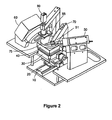
- FIG. 2 An example of the apparatus used in the present invention is shown in Figure 2 .
- the apparatus of the present invention utilizes an x-ray source with collimation device and an area x-ray detector with its positioning optimized for a particular range of coverage within reciprocal space.
- the apparatus preferably comprises three interacting components: the collimated x-ray source components, the sample handling apparatus, and the area detector.
- the x-ray area detector 60 is mounted to a rigid base. Also mounted to the rigid base are the x-ray source 50, monochromator 51, and x-ray collimator 55.
- the sample handling apparatus consists of a sample motion apparatus, having a y-stage 10, an x-stage 20, a z-stage 30, and a ⁇ -stage 40. Also shown is an optional video microscope 80.
- the example application of the invention is primarily designed to handle sample 70 up to 300 millimeters in diameter, but the apparatus can be readily modified to handle larger or smaller samples.
- a preferred aspect of the invention is that it fixes the x-ray source and detector in specific spatial locations.
- the sample handling apparatus is mounted in such a way to not spatially interfere with the x-ray source, collimator or detector, but allow sample motion sufficient to cover all locations of the sample surface, and to also allow in-plane rotation at all of these locations.
- the sample motion stages are arranged in the following order from top to bottom: ⁇ rotation, z (vertical) motion, x linear motion, and y linear motion. These sample motions are configured in such a way as to allow full sample motion, as well as close proximity of the area detector to the wafer measure point 75.
- the fixed ranges of 2 ⁇ and ⁇ are optimized for a group of specific material systems, by placing the detector 60 and x-ray source 50 at very specific permanent locations.
- the maximum amount of texture information can be extracted from the measurement process through a new and more efficient analysis.
- a Hi-Star® multiwire gas proportional counter produced by Bruker AXS, Madison, WI, is currently a preferred area x-ray detector suitable for diffraction data acquisition in polycrystalline materials. It offers high sensitivity combined with a large total circular detection area that is 11.5 centimeters in diameter. Any other suitable two-dimensional type area detector with sufficient angular range and spatial resolution can be employed, including, but not limited to, x-ray image charge-coupled device (CCD) cameras, x-ray image plates, and other 2-D x-ray detectors. Preferably, such area detector has large area, high sensitivity, and a mechanism for rapid transfer of data to electronic digital format.
- CCD x-ray image charge-coupled device
- the x-ray source can be a standard monochromatic sealed beam tube, a rotating anode, an integrated sealed tube - polycaplilary optics system, an integrated sealed tube - grated mirror system or any other suitable source for generating and collimating x-rays.
- the phase composition of the sample is determined by a computer-based quantitative phase analyzer, which may comprise a computer, central processor unit (CPU), microprocessor, integrated circuitry, operated and arranged to collect and process diffraction data for determining phase composition of textured polycrystalline thin film or any other multiphase sample, according to the method described hereinabove.
- a computer-based quantitative phase analyzer which may comprise a computer, central processor unit (CPU), microprocessor, integrated circuitry, operated and arranged to collect and process diffraction data for determining phase composition of textured polycrystalline thin film or any other multiphase sample, according to the method described hereinabove.
- Such quantitative phase analyzer preferably comprises a phase composition determination protocol for computationally carrying out the phase composition determination method described hereinabove.
- the phase composition determination protocol can be embodied in any suitable form, such as software operable in a general-purpose programmable digital computer. Alternatively, the protocol may be hard-wired in circuitry of a microelectronic computational module, embodied as firmware
Landscapes
- Chemical & Material Sciences (AREA)
- Crystallography & Structural Chemistry (AREA)
- Physics & Mathematics (AREA)
- Health & Medical Sciences (AREA)
- Life Sciences & Earth Sciences (AREA)
- Analytical Chemistry (AREA)
- Biochemistry (AREA)
- General Health & Medical Sciences (AREA)
- General Physics & Mathematics (AREA)
- Immunology (AREA)
- Pathology (AREA)
- Analysing Materials By The Use Of Radiation (AREA)
- Sampling And Sample Adjustment (AREA)
Claims (21)
- Verfahren zum quantitativen Bestimmen der Phasenzusammensetzung eines Probengemischs, das strukturiertes polykristallines Material in mehreren Phasen umfasst, wobei das Verfahren folgende Schritte umfasst:(a) Aufzeichnen mehrerer unvollständiger Laue-Diagramme für die verschiedenen Phasen der Probenmischung, mittels folgender Schritte, umfassend:i) Bestrahlen eines Messbereichs auf dem Probengemisch mit Strahlungsenergie von einer Strahlungsquelle;ii) Detektieren der Strahlungsenergie, die von dem Probengemisch an einen Detektionsort gebeugt wird, wobei der Detektionsort so positioniert ist, dass eine Vielzahl von Beugungskreisen mit einem einzelnen Datensatz des Detektors aufgenommen werden kann; undv) Erzeugen eines Beugungsbildes, das mehrere unvollständige Laue-Diagramme für die mehreren Phasen enthält;(b) Berechnen einer vollständigen Laue-Reflexdichteverteilung für eine erste Schar von kristallographischen Ebenen (hkl) einer ersten Phase, die in dem Probengemisch enthalten ist, auf Grundlage der unvollständigen Laue-Diagramme, die auf dem Beugungsbild aufgezeichnet sind;(c) Korrigieren der auf dem Beugungsbild für die erste Schar von kristallographischen Ebenen (hkl) der ersten Phase aufgezeichneten Beugungsintensitäten, um daraus die kristallographische Strukturierung zu entfernen, unter Verwendung der vollständigen Laue-Reflexdichteverteilung, die in Schritt (b) berechnet wurde;(d) Integrieren der korrigierten Werte der Beugungsintensitäten für die erste Schar kristallographischer Ebenen (hkl) der ersten Phase;(e) Wiederholen der Schritte (b)-(d), um integrierte und korrigierte Beugungsintensitäten für alle Phasen, die in dem Probengemisch enthalten sind, zu erhalten; und(f) Berechnen der Phasenzusammensetzung des Probengemisches aus den korrigierten und integrierten Beugungsintensitäten, die aus den Schritten (d) und € erhalten wurden.
- Verfahren gemäß Anspruch 1, wobei das Probengemisch zwei strukturierte, polykristalline Materialien bekannter Kristallstrukturen und Gitterparameter umfasst.
- Verfahren gemäß Anspruch 1, wobei das Probengemisch mehr als zwei strukturierte polykristalline Materialien bekannter Kristallstrukturen und Gitterparameter umfasst.
- Verfahren gemäß Anspruch 1, wobei die Phasenzusammensetzung des Probengemisches aus den korrigierten und integrierten Beugungsintensitäten durch eine Methode des direkten Vergleichs berechnet wird.
- Verfahren gemäß Anspruch 1, wobei die Phasenzusammensetzung des Probengemisches berechnet wird aus den korrigierten und integrierten Beugungsintensitäten nach einer Methode ohne Vergleichsstandard.
- Verfahren gemäß Anspruch 1, wobei die Phasenzusammensetzung des Probengemisches aus den korrigierten und integrierten Beugungsintensitäten berechnet wird gemäß eines Zuordnungsverfahrens ohne Vergleichsstandard.
- Verfahren gemäß Anspruch 1, wobei die vollständige Laue-Reflexdichteverteilung für eine Schar von kristallographischen Ebenen (hkl) einer Phase in Schritt (b) berechnet wird durch die Schritte umfassend:(i) Berechnen der Orientierungsverteilungsfunktion (ODF) auf Grundlage der mehreren unvollständigen Laue-Diagramme, die in Schritt (a) aufgenommen wurden; und(ii) Berechnen der vollständigen Laue-Reflexdichteverteilung für die Schar von kristallographischen Ebenen (hkl) für die Phase aus der Orientierungsverteilungsfunktion.
- Verfahren nach Anspruch 7, wobei die Orientierungsverteilungsfunktion in Schritt (i) berechnet wird unter Verwendung eines direkten Verfahrens mit beliebiger Schrittauflösung.
- Verfahren gemäß Anspruch 8, wobei das direkte Verfahren ausgewählt wird aus der Gruppe bestehend aus Williams-Imhof-Matthies-Vinel (WIMV)-Verfahren und dem Verfahren der beliebig gewählten Zellen (ADC-Verfahren).
- Verfahren gemäß Anspruch 8, wobei der beliebige Schritt nicht größer als fünf Grad ist.
- Verfahren gemäß Anspruch 8, wobei der beliebige Schritt nicht größer als ein Grad ist.
- Verfahren nach Anspruch 1, wobei in Schritt (a)(ii) der Detektionsort in hinreichender Nähe zu dem Messbereich zum Aufnehmen mindestens eines Beugungskreises von nicht weniger als 90 Grad, und wobei die vollständige Laue-Reflexdichteverteilung in Schritt (b) direkt berechnet wird für eine bestimmte Schar von Kristallebenen (hkl), die durch den zumindest einen Beugungskreis repräsentiert ist, unter Verwendung einer Normalisierungsgleichung.
- Verfahren gemäß Anspruch 12, wobei der Detektionsort in hinreichender Nähe zu dem Messbereich ist, um zumindest einen Beugungskreis von ungefähr 360 Grad aufzunehmen.
- Verfahren gemäß Anspruch 1, wobei in Schritt (a)(ii) der Detektionsort in einer festen räumlichen Beziehung zur Strahlungsquelle steht.
- Verfahren zur quantitativen Bestimmung der Phasenzusammensetzung eines Probengemischs, das strukturierte polykristalline Materialien in mehreren Phasen umfasst, wobei das Verfahren folgende Schritte umfasst:(a) Aufzeichnen mehrerer unvollständiger Laue-Diagramme des Probengemischs, durch die Schritte umfassend:(i) Bestrahlen eines Messbereichs auf dem Probengemisch mit Strahlungsenergie von einer Strahlungsquelle;(ii) Detektieren der von dem Probengemisch an einen Detektionsort gebeugten Strahlungsenergie, wobei der Detektionsort so positioniert ist, dass eine Vielzahl von Beugungskreisen mit einem einzelnen Datensatz des Detektrors aufgenommen werden kann; und(iv) Erzeugen eines Beugungsbildes, das mehrere unvollständige Laue-Diagramme für die mehreren Phasen enthält;(b) Mitteln der im Beugungsbild aufgezeichneten Beugungsintensitäten für eine erste Schar von kristallographischen Ebenen (hkl) einer ersten Phase über alle kristallographischen Orientierungen der unvollständigen Laue-Diagramme, die auf dem Beugungsbild aufgezeichnet wurden;(c) Integrieren der gemittelten Werte der Beugungsintensitäten für die erste Schar von kristallographischen Ebenen (hkl) der ersten Phase in Schritt (b);(d) Korrigieren der integrierten Beugungsintensitäten in Schritt (c) mit einem Korrekturfaktor, welcher das Verhältnis der vollständigen Laue-Reflexdichteverteilung über der unvollständigen Laue-Reflexintensitätsverteilung ist, gemessen für die erste Schar von kristallographischen Ebenen (hkl) der ersten Phase;(e) Wiederholen der Schritte (b)-(d), um integrierte und korrigierte Beugungsintensitäten für alle Phasen, die in dem Probengemisch enthalten sind, zu erhalten; und(f) Berechnen der Phasenzusammensetzung des Probengemischs aus den korrigierten und integrierten Beugungsintensitäten, die in den Schritten (d) und (e) erhalten wurden.
- Verfahren gemäß Anspruch 15, wobei das Probengemisch zwei strukturierte polykristalline Materialien von bekannten Kristallstrukturen und Gitterparametern umfasst.
- Verfahren gemäß Anspruch 15, wobei das Probengemisch mehr als zwei strukturierte polykristalline Materialien von bekannten Kristallstrukturen und Gitterparametern umfasst.
- Verfahren gemäß Anspruch 15, wobei die Phasenzusammensetzung des Probengemisches berechnet wird aus den korrigierten und integrierten Beugungsintensitäten gemäß eines Verfahrens des direkten Vergleichs.
- Verfahren gemäß Anspruch 15, wobei die Phasenzusammensetzung des Probengemischs berechnet wird aus den korrigierten und integrierten Beugungsintensitäten gemäß eines Verfahrens ohne Vergleichsstandard.
- Verfahren gemäß Anspruch 15, wobei die Phasenzusammensetzung des Probengemischs berechnet wird aus den korrigierten und integrierten Beugungsintensitäten gemäß eines Zuordnungsverfahrens ohne Vergleichsstandard.
- Eine Vorrichtung zur quantitativen Phasenbestimmung zur Bestimmung der Phasenzusammensetzung eines Probengemischs, das strukturierte polykristalline Materialien in mehreren Phasen umfasst, die Vorrichtung umfassend:Eine Probe, welche eine Mischung aus zwei oder mehr strukturierten polykristallinen Materialien umfasst, wobei die Probe eine zugeohörige Probenebene definiert;Eine Strahlungsquelle um Strahlungsenergie auf einen Messpunkt auf der Probe zu richten;Einen zweidimensionalen Detektor, der von der Probe an den Messpunkt gebeugte Strahlungsenergie registriert, wobei die Strahlungsquelle und der zweidimensionale Detektor in einer festen räumlichen Beziehung zueinander stehen und hinreichend nah zu dem Messpunkt sind, um eine Vielzahl von Beugungskreisen in einem einzelnen Datensatz des Flächendetektors aufzunehmen;Eine Probenbewegungseinheit zum Verfahren der Probe in der Probenebene; undEinen computergestützten quantitativen Phasenanalysator, der aufgebaut und geeignet ist für die Aufzeichnung und Verarbeitung von Beugungsdaten, zur Analyse der Phasenzusammensetzung einer Probe.
Applications Claiming Priority (3)
| Application Number | Priority Date | Filing Date | Title |
|---|---|---|---|
| US10/205,717 US6678347B1 (en) | 2002-07-26 | 2002-07-26 | Method and apparatus for quantitative phase analysis of textured polycrystalline materials |
| US205717 | 2002-07-26 | ||
| PCT/US2003/021330 WO2004011919A1 (en) | 2002-07-26 | 2003-07-09 | Quantitative phase analysis of textured polycrystalline materials |
Publications (3)
| Publication Number | Publication Date |
|---|---|
| EP1540319A1 EP1540319A1 (de) | 2005-06-15 |
| EP1540319A4 EP1540319A4 (de) | 2007-08-08 |
| EP1540319B1 true EP1540319B1 (de) | 2008-05-21 |
Family
ID=29780255
Family Applications (1)
| Application Number | Title | Priority Date | Filing Date |
|---|---|---|---|
| EP03771582A Expired - Lifetime EP1540319B1 (de) | 2002-07-26 | 2003-07-09 | Quantitative phasenanalyse strukturierter polykristalliner materialien |
Country Status (8)
| Country | Link |
|---|---|
| US (1) | US6678347B1 (de) |
| EP (1) | EP1540319B1 (de) |
| JP (1) | JP2005534028A (de) |
| AT (1) | ATE396394T1 (de) |
| AU (1) | AU2003248859A1 (de) |
| DE (1) | DE60321187D1 (de) |
| TW (1) | TWI241413B (de) |
| WO (1) | WO2004011919A1 (de) |
Families Citing this family (17)
| Publication number | Priority date | Publication date | Assignee | Title |
|---|---|---|---|---|
| US20040131152A1 (en) * | 2002-11-08 | 2004-07-08 | Bede Plc | Apparatus and method for determining a parameter of a sample |
| US7269245B2 (en) * | 2004-07-30 | 2007-09-11 | Bruker Axs, Inc. | Combinatorial screening system and X-ray diffraction and Raman spectroscopy |
| ITFI20050137A1 (it) * | 2005-06-20 | 2006-12-21 | Giovanni Berti | Apparecchiatura mobile per irragiamento e rilevazione di radiazioni |
| JP4597892B2 (ja) * | 2006-03-29 | 2010-12-15 | 京セラ株式会社 | 誘電体磁器の評価方法 |
| US20070259052A1 (en) * | 2006-05-05 | 2007-11-08 | Shire International Licensing B.V. | Assay for lanthanum hydroxycarbonate |
| RU2362149C1 (ru) * | 2008-01-09 | 2009-07-20 | Государственное образовательное учреждение высшего профессионального образования "Южно-Уральский государственный университет" | Способ определения концентраций элемента и фазы, включающей данный элемент, в веществе сложного химического состава |
| US7755752B1 (en) | 2008-04-07 | 2010-07-13 | Kla-Tencor Corporation | Combined modulated optical reflectance and photoreflectance system |
| JP5598926B2 (ja) * | 2011-09-26 | 2014-10-01 | 株式会社リガク | X線回折測定データの解析方法 |
| JP5828795B2 (ja) | 2012-04-04 | 2015-12-09 | 信越化学工業株式会社 | 多結晶シリコンの結晶配向度評価方法、多結晶シリコン棒の選択方法、および単結晶シリコンの製造方法 |
| RU2524454C1 (ru) * | 2013-04-11 | 2014-07-27 | Федеральное государственное бюджетное образовательное учреждение высшего профессионального образования "Национальный минерально-сырьевой университет "Горный" | Способ определения концентрации элемента в веществе сложного химического состава |
| EP2818851B1 (de) * | 2013-06-26 | 2023-07-26 | Malvern Panalytical B.V. | Bildgebende Beugung |
| EP3425379B1 (de) * | 2016-02-29 | 2022-02-16 | Rigaku Corporation | Vorrichtung für quantitative kristallphasenanalyse und verfahren für quantitative kristallphasenanalyse |
| JP6606706B2 (ja) * | 2016-06-24 | 2019-11-20 | 株式会社リガク | 処理方法、処理装置および処理プログラム |
| FR3058224B1 (fr) * | 2016-11-02 | 2018-11-30 | Renault S.A.S | Procede de caracterisation d'une orientation preferentielle d'un ensemble de particules d'une electrode d'un systeme electrochimique |
| KR102235852B1 (ko) * | 2019-11-11 | 2021-04-02 | 가천대학교 산학협력단 | 광을 이용한 측정 장치 및 측정 방법 |
| CN113447506B (zh) * | 2020-03-26 | 2022-07-08 | 国标(北京)检验认证有限公司 | 一种双相钛合金相比例的快速分析方法 |
| CN113533400B (zh) * | 2021-07-06 | 2024-04-12 | 合肥工业大学 | 一种针对挤压棒材的高速、精确x射线织构测试方法 |
Family Cites Families (7)
| Publication number | Priority date | Publication date | Assignee | Title |
|---|---|---|---|---|
| US4592082A (en) | 1984-08-10 | 1986-05-27 | The United States Of America As Represented By The United States Department Of Energy | Quantitative determination of mineral composition by powder X-ray diffraction |
| US5414747A (en) * | 1993-02-22 | 1995-05-09 | The Penn State Research Foundation | Method and apparatus for in-process analysis of polycrystalline films and coatings by x-ray diffraction |
| DE4331317A1 (de) | 1993-09-15 | 1995-03-16 | Philips Patentverwaltung | Untersuchungsverfahren zur Auswertung ortsabhängiger Spektren |
| DE69839390T2 (de) | 1997-12-22 | 2009-05-20 | Panalytical B.V. | Referenzlose phasenanalyse mit einem diffraktometer |
| WO1999060388A1 (en) * | 1998-05-15 | 1999-11-25 | The Trustees Of The Stevens Institute Of Technology | Method and apparatus for x-ray analysis of particle size (xaps) |
| US6301330B1 (en) | 1999-07-30 | 2001-10-09 | Hypernex, Inc. | Apparatus and method for texture analysis on semiconductor wafers |
| US6882739B2 (en) * | 2001-06-19 | 2005-04-19 | Hypernex, Inc. | Method and apparatus for rapid grain size analysis of polycrystalline materials |
-
2002
- 2002-07-26 US US10/205,717 patent/US6678347B1/en not_active Expired - Lifetime
-
2003
- 2003-07-09 EP EP03771582A patent/EP1540319B1/de not_active Expired - Lifetime
- 2003-07-09 AU AU2003248859A patent/AU2003248859A1/en not_active Abandoned
- 2003-07-09 JP JP2004524574A patent/JP2005534028A/ja active Pending
- 2003-07-09 DE DE60321187T patent/DE60321187D1/de not_active Expired - Fee Related
- 2003-07-09 WO PCT/US2003/021330 patent/WO2004011919A1/en not_active Ceased
- 2003-07-09 AT AT03771582T patent/ATE396394T1/de not_active IP Right Cessation
- 2003-07-24 TW TW092120199A patent/TWI241413B/zh active
Also Published As
| Publication number | Publication date |
|---|---|
| TW200403448A (en) | 2004-03-01 |
| US6678347B1 (en) | 2004-01-13 |
| JP2005534028A (ja) | 2005-11-10 |
| EP1540319A4 (de) | 2007-08-08 |
| WO2004011919A1 (en) | 2004-02-05 |
| EP1540319A1 (de) | 2005-06-15 |
| TWI241413B (en) | 2005-10-11 |
| AU2003248859A1 (en) | 2004-02-16 |
| ATE396394T1 (de) | 2008-06-15 |
| DE60321187D1 (de) | 2008-07-03 |
Similar Documents
| Publication | Publication Date | Title |
|---|---|---|
| EP1540319B1 (de) | Quantitative phasenanalyse strukturierter polykristalliner materialien | |
| He | Introduction to two-dimensional X-ray diffraction | |
| US6882739B2 (en) | Method and apparatus for rapid grain size analysis of polycrystalline materials | |
| EP0117293B1 (de) | Verfahren zur Spannungsmessung durch Röntgenstrahlendiffraktometrie | |
| US6301330B1 (en) | Apparatus and method for texture analysis on semiconductor wafers | |
| Bunge et al. | Neutron Diffraction Texture Analysis Using a 2θ‐Position Sensitive Detector | |
| JP2001124711A (ja) | 蛍光x線分析方法及び試料構造の評価方法 | |
| JP2004045369A (ja) | 多結晶材料の配向性の評価方法 | |
| US6792075B2 (en) | Method and apparatus for thin film thickness mapping | |
| JP4115542B2 (ja) | ディフラクトグラムによる無標準相分析法 | |
| Hohlwein et al. | Collection of Bragg data with a neutron flat-cone diffractometer | |
| CN113447506B (zh) | 一种双相钛合金相比例的快速分析方法 | |
| He | Two-dimensional powder diffraction | |
| Fewster | Reciprocal space mapping | |
| O’Connor et al. | Improving the accuracy of Rietveld-derived lattice parameters by an order of magnitude | |
| JPH11248653A (ja) | 全反射螢光x線分析方法及び装置 | |
| JPH07146260A (ja) | 汚染元素濃度分析装置 | |
| JPH0735708A (ja) | 蛍光x線分析方法 | |
| Wcislak et al. | Diffraction Profile Pole Figures Measured with a Position Sensitive Detector | |
| Winegar | Measurement of crystallographic texture at chalk river nuclear laboratories | |
| WO2001096841A2 (en) | X-ray reflectivity apparatus and method | |
| Renner et al. | Vertical dispersion Johann x-ray spectrometer with asymmetrically cut crystal | |
| JPH0344544A (ja) | 結晶基板の内部歪み測定方法 | |
| He | 2.5. Two-dimensional powder diffraction | |
| Parrish et al. | Specimen factors, angle, intensity, and profile-shape measurement |
Legal Events
| Date | Code | Title | Description |
|---|---|---|---|
| PUAI | Public reference made under article 153(3) epc to a published international application that has entered the european phase |
Free format text: ORIGINAL CODE: 0009012 |
|
| 17P | Request for examination filed |
Effective date: 20050125 |
|
| AK | Designated contracting states |
Kind code of ref document: A1 Designated state(s): AT BE BG CH CY CZ DE DK EE ES FI FR GB GR HU IE IT LI LU MC NL PT RO SE SI SK TR |
|
| AX | Request for extension of the european patent |
Extension state: AL LT LV MK |
|
| DAX | Request for extension of the european patent (deleted) | ||
| RAP1 | Party data changed (applicant data changed or rights of an application transferred) |
Owner name: NOVA MEASURING INSTRUMENTS LIMITED |
|
| A4 | Supplementary search report drawn up and despatched |
Effective date: 20070705 |
|
| GRAP | Despatch of communication of intention to grant a patent |
Free format text: ORIGINAL CODE: EPIDOSNIGR1 |
|
| GRAS | Grant fee paid |
Free format text: ORIGINAL CODE: EPIDOSNIGR3 |
|
| GRAA | (expected) grant |
Free format text: ORIGINAL CODE: 0009210 |
|
| AK | Designated contracting states |
Kind code of ref document: B1 Designated state(s): AT BE BG CH CY CZ DE DK EE ES FI FR GB GR HU IE IT LI LU MC NL PT RO SE SI SK TR |
|
| REG | Reference to a national code |
Ref country code: GB Ref legal event code: FG4D |
|
| REG | Reference to a national code |
Ref country code: CH Ref legal event code: EP |
|
| REF | Corresponds to: |
Ref document number: 60321187 Country of ref document: DE Date of ref document: 20080703 Kind code of ref document: P |
|
| REG | Reference to a national code |
Ref country code: IE Ref legal event code: FG4D |
|
| PG25 | Lapsed in a contracting state [announced via postgrant information from national office to epo] |
Ref country code: SI Free format text: LAPSE BECAUSE OF FAILURE TO SUBMIT A TRANSLATION OF THE DESCRIPTION OR TO PAY THE FEE WITHIN THE PRESCRIBED TIME-LIMIT Effective date: 20080521 |
|
| PG25 | Lapsed in a contracting state [announced via postgrant information from national office to epo] |
Ref country code: FI Free format text: LAPSE BECAUSE OF FAILURE TO SUBMIT A TRANSLATION OF THE DESCRIPTION OR TO PAY THE FEE WITHIN THE PRESCRIBED TIME-LIMIT Effective date: 20080521 Ref country code: ES Free format text: LAPSE BECAUSE OF FAILURE TO SUBMIT A TRANSLATION OF THE DESCRIPTION OR TO PAY THE FEE WITHIN THE PRESCRIBED TIME-LIMIT Effective date: 20080901 |
|
| NLV1 | Nl: lapsed or annulled due to failure to fulfill the requirements of art. 29p and 29m of the patents act | ||
| PG25 | Lapsed in a contracting state [announced via postgrant information from national office to epo] |
Ref country code: NL Free format text: LAPSE BECAUSE OF FAILURE TO SUBMIT A TRANSLATION OF THE DESCRIPTION OR TO PAY THE FEE WITHIN THE PRESCRIBED TIME-LIMIT Effective date: 20080521 Ref country code: AT Free format text: LAPSE BECAUSE OF FAILURE TO SUBMIT A TRANSLATION OF THE DESCRIPTION OR TO PAY THE FEE WITHIN THE PRESCRIBED TIME-LIMIT Effective date: 20080521 |
|
| PG25 | Lapsed in a contracting state [announced via postgrant information from national office to epo] |
Ref country code: DK Free format text: LAPSE BECAUSE OF FAILURE TO SUBMIT A TRANSLATION OF THE DESCRIPTION OR TO PAY THE FEE WITHIN THE PRESCRIBED TIME-LIMIT Effective date: 20080521 Ref country code: CZ Free format text: LAPSE BECAUSE OF FAILURE TO SUBMIT A TRANSLATION OF THE DESCRIPTION OR TO PAY THE FEE WITHIN THE PRESCRIBED TIME-LIMIT Effective date: 20080521 Ref country code: SE Free format text: LAPSE BECAUSE OF FAILURE TO SUBMIT A TRANSLATION OF THE DESCRIPTION OR TO PAY THE FEE WITHIN THE PRESCRIBED TIME-LIMIT Effective date: 20080821 Ref country code: PT Free format text: LAPSE BECAUSE OF FAILURE TO SUBMIT A TRANSLATION OF THE DESCRIPTION OR TO PAY THE FEE WITHIN THE PRESCRIBED TIME-LIMIT Effective date: 20081021 |
|
| PG25 | Lapsed in a contracting state [announced via postgrant information from national office to epo] |
Ref country code: BE Free format text: LAPSE BECAUSE OF FAILURE TO SUBMIT A TRANSLATION OF THE DESCRIPTION OR TO PAY THE FEE WITHIN THE PRESCRIBED TIME-LIMIT Effective date: 20080521 Ref country code: SK Free format text: LAPSE BECAUSE OF FAILURE TO SUBMIT A TRANSLATION OF THE DESCRIPTION OR TO PAY THE FEE WITHIN THE PRESCRIBED TIME-LIMIT Effective date: 20080521 Ref country code: RO Free format text: LAPSE BECAUSE OF FAILURE TO SUBMIT A TRANSLATION OF THE DESCRIPTION OR TO PAY THE FEE WITHIN THE PRESCRIBED TIME-LIMIT Effective date: 20080521 |
|
| REG | Reference to a national code |
Ref country code: CH Ref legal event code: PL |
|
| PLBE | No opposition filed within time limit |
Free format text: ORIGINAL CODE: 0009261 |
|
| STAA | Information on the status of an ep patent application or granted ep patent |
Free format text: STATUS: NO OPPOSITION FILED WITHIN TIME LIMIT |
|
| PG25 | Lapsed in a contracting state [announced via postgrant information from national office to epo] |
Ref country code: MC Free format text: LAPSE BECAUSE OF NON-PAYMENT OF DUE FEES Effective date: 20080731 |
|
| 26N | No opposition filed |
Effective date: 20090224 |
|
| GBPC | Gb: european patent ceased through non-payment of renewal fee |
Effective date: 20080821 |
|
| REG | Reference to a national code |
Ref country code: IE Ref legal event code: MM4A |
|
| PG25 | Lapsed in a contracting state [announced via postgrant information from national office to epo] |
Ref country code: EE Free format text: LAPSE BECAUSE OF FAILURE TO SUBMIT A TRANSLATION OF THE DESCRIPTION OR TO PAY THE FEE WITHIN THE PRESCRIBED TIME-LIMIT Effective date: 20080521 Ref country code: DE Free format text: LAPSE BECAUSE OF NON-PAYMENT OF DUE FEES Effective date: 20090203 Ref country code: BG Free format text: LAPSE BECAUSE OF FAILURE TO SUBMIT A TRANSLATION OF THE DESCRIPTION OR TO PAY THE FEE WITHIN THE PRESCRIBED TIME-LIMIT Effective date: 20080821 |
|
| REG | Reference to a national code |
Ref country code: FR Ref legal event code: ST Effective date: 20090331 |
|
| PG25 | Lapsed in a contracting state [announced via postgrant information from national office to epo] |
Ref country code: CH Free format text: LAPSE BECAUSE OF NON-PAYMENT OF DUE FEES Effective date: 20080731 Ref country code: LI Free format text: LAPSE BECAUSE OF NON-PAYMENT OF DUE FEES Effective date: 20080731 |
|
| PG25 | Lapsed in a contracting state [announced via postgrant information from national office to epo] |
Ref country code: IE Free format text: LAPSE BECAUSE OF NON-PAYMENT OF DUE FEES Effective date: 20080709 |
|
| PG25 | Lapsed in a contracting state [announced via postgrant information from national office to epo] |
Ref country code: FR Free format text: LAPSE BECAUSE OF NON-PAYMENT OF DUE FEES Effective date: 20080731 Ref country code: IT Free format text: LAPSE BECAUSE OF FAILURE TO SUBMIT A TRANSLATION OF THE DESCRIPTION OR TO PAY THE FEE WITHIN THE PRESCRIBED TIME-LIMIT Effective date: 20080521 |
|
| PG25 | Lapsed in a contracting state [announced via postgrant information from national office to epo] |
Ref country code: GB Free format text: LAPSE BECAUSE OF NON-PAYMENT OF DUE FEES Effective date: 20080821 |
|
| PG25 | Lapsed in a contracting state [announced via postgrant information from national office to epo] |
Ref country code: LU Free format text: LAPSE BECAUSE OF NON-PAYMENT OF DUE FEES Effective date: 20080709 Ref country code: HU Free format text: LAPSE BECAUSE OF FAILURE TO SUBMIT A TRANSLATION OF THE DESCRIPTION OR TO PAY THE FEE WITHIN THE PRESCRIBED TIME-LIMIT Effective date: 20081122 Ref country code: CY Free format text: LAPSE BECAUSE OF FAILURE TO SUBMIT A TRANSLATION OF THE DESCRIPTION OR TO PAY THE FEE WITHIN THE PRESCRIBED TIME-LIMIT Effective date: 20080521 |
|
| PG25 | Lapsed in a contracting state [announced via postgrant information from national office to epo] |
Ref country code: TR Free format text: LAPSE BECAUSE OF FAILURE TO SUBMIT A TRANSLATION OF THE DESCRIPTION OR TO PAY THE FEE WITHIN THE PRESCRIBED TIME-LIMIT Effective date: 20080521 |
|
| PG25 | Lapsed in a contracting state [announced via postgrant information from national office to epo] |
Ref country code: GR Free format text: LAPSE BECAUSE OF FAILURE TO SUBMIT A TRANSLATION OF THE DESCRIPTION OR TO PAY THE FEE WITHIN THE PRESCRIBED TIME-LIMIT Effective date: 20080822 |