EP1540264B1 - Dispositif de freinage pour projectile d'artillerie stabilisee par rotation a correction de trajectoire - Google Patents
Dispositif de freinage pour projectile d'artillerie stabilisee par rotation a correction de trajectoire Download PDFInfo
- Publication number
- EP1540264B1 EP1540264B1 EP03775150A EP03775150A EP1540264B1 EP 1540264 B1 EP1540264 B1 EP 1540264B1 EP 03775150 A EP03775150 A EP 03775150A EP 03775150 A EP03775150 A EP 03775150A EP 1540264 B1 EP1540264 B1 EP 1540264B1
- Authority
- EP
- European Patent Office
- Prior art keywords
- braking device
- holding ring
- projectile
- braking
- screen
- Prior art date
- Legal status (The legal status is an assumption and is not a legal conclusion. Google has not performed a legal analysis and makes no representation as to the accuracy of the status listed.)
- Expired - Lifetime
Links
- 239000004753 textile Substances 0.000 claims description 12
- 230000003014 reinforcing effect Effects 0.000 claims description 4
- 238000009825 accumulation Methods 0.000 claims description 3
- 239000004744 fabric Substances 0.000 description 7
- 230000000694 effects Effects 0.000 description 3
- 239000000945 filler Substances 0.000 description 2
- 230000002787 reinforcement Effects 0.000 description 2
- 238000009958 sewing Methods 0.000 description 2
- 230000004913 activation Effects 0.000 description 1
- 230000015572 biosynthetic process Effects 0.000 description 1
- 238000005422 blasting Methods 0.000 description 1
- 238000007664 blowing Methods 0.000 description 1
- 238000011161 development Methods 0.000 description 1
- 230000018109 developmental process Effects 0.000 description 1
- 230000001747 exhibiting effect Effects 0.000 description 1
- 230000000977 initiatory effect Effects 0.000 description 1
- 230000000284 resting effect Effects 0.000 description 1
- 239000013589 supplement Substances 0.000 description 1
- 230000007704 transition Effects 0.000 description 1
Images
Classifications
-
- F—MECHANICAL ENGINEERING; LIGHTING; HEATING; WEAPONS; BLASTING
- F42—AMMUNITION; BLASTING
- F42B—EXPLOSIVE CHARGES, e.g. FOR BLASTING, FIREWORKS, AMMUNITION
- F42B10/00—Means for influencing, e.g. improving, the aerodynamic properties of projectiles or missiles; Arrangements on projectiles or missiles for stabilising, steering, range-reducing, range-increasing or fall-retarding
- F42B10/32—Range-reducing or range-increasing arrangements; Fall-retarding means
- F42B10/48—Range-reducing, destabilising or braking arrangements, e.g. impact-braking arrangements; Fall-retarding means, e.g. balloons, rockets for braking or fall-retarding
- F42B10/50—Brake flaps, e.g. inflatable
Definitions
- the invention relates to a braking device according to the preamble of claim 1.
- a braking device is known from DE 100 23 345 A1 known.
- the present invention is based on the technical problem of developing a braking device of the generic type in such a way that, on the one hand, a noticeably increased braking effect results on the other hand in stable ballistics during the initiation of the braking device.
- This task is based on the finding that a star-shaped arrangement of radially expandable brake segments, despite the formation of vortices in the gaps between the brake segments, does not yet provide the desirable brake coefficients for the fastest possible and more defined transition from the ballistic transfer path to a steepened descent path.
- the braking effect can be improved if the free gussets between the individual brake segments are spanned by acute-angled triangular wipes, which are initially folded together with the brake segments in the storage space under a support hood when moving out of the gun and then with the blasting of Hood to be released for centrifugal assisted erection; but the combination of hinge-hinged brake segments and textiles clamped therebetween is extremely difficult to install and also has the disadvantage that local mechanical stresses due to the compact pressure in the storage space to the area Damage to the textile gap filler can lead.
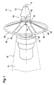
- an igniter 11 which is designed for screwing into the ogive of an artillery projectile 12, in its frustoconical lateral surface 13 on a circumferentially radially recessed storage space 14.
- This carries its rear wall 25 axially opposite, so in the direction of travel before the storage space 14, a ring 15 to which the inner circumference 31 of a coaxial in operative position circular disk-shaped braking element is hinged in the form of a flight direction against the stretchable textile screen 16.
- This textile brake element is folded in its depot and transfer position from the ring 15 forth uniformly around the projectile longitudinal axis 17 around in the storage space 14 and overlapped by a hood until it is released by the blowing off of the hood for centrifugal radial issuing in the umbrella shape ,
- Corrioliskraft in the articulation of the brake element can be selectively reduced to the ring 15
- the thus located on the inner periphery of the hollow cylinder force elements 19 are used to radially ceremoniessprengen when stored on the receptacle 18 hollow cylinder of the hood and thus disassemble this cover disassembled into defined pieces of storage space 14.
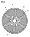
- This centrifugal force issuing of the annular disc brake screen 16 is further promoted by the fact that - the shield at least by seam seams, but optionally also by sewing reinforcements compared to the cloth surface with a defined mass accumulation 29 is equipped with the moment of inertia for To increase a rapid and stable issuing from the folded position in the final shape given from the cut in the interest of a fast-acting large, symmetrical inflow surface for maximum braking effect.
- braking screen 16 which, however, flows against its outer circumferential surface, essentially a textile structure surrounding the fastening ring 15 in the form of an annular disk.
- this is designed from the cut, under the influence of centrifugal forces not to be clamped in a substantially flat and therefore flatter end textile disc, but only up to a relatively large angle relative to the projectile axis 17, in the maximum issued state without fluttering along the Edge always the same frusto-conical geometry stable to be able to comply.
- a circular cut cloth 33 is equipped by radially extending dart so with a reduced outer circumference 32, characterized in that the clamping movement to the shape of a flat obtuse-angled hollow truncated cone is limited, by means of longitudinal generatrix of the conical surface applied reinforcing ribbons 34 on the inner circumference 31 of the forwardly pointing small base a radial distance bridging to the retaining ring 15 is hinged and rearwardly, along the outer periphery 32, with a circumferential mass accumulation 29 for reinforcement equipped with centrifugal release forces; wherein the ring 15 in the front end region of the storage space 14, temporarily slipping relative to the projectile twist, is axially clamped in the contour of the igniter 12.
Landscapes
- Physics & Mathematics (AREA)
- Fluid Mechanics (AREA)
- Engineering & Computer Science (AREA)
- General Engineering & Computer Science (AREA)
- Aiming, Guidance, Guns With A Light Source, Armor, Camouflage, And Targets (AREA)
- Braking Arrangements (AREA)
- Toys (AREA)
Claims (4)
- Dispositif de freinage comprenant, dans la zone du détonateur de l'ogive d'un projectile d'artillerie (12) à correction de trajectoire, sous un capot éjectable, un élément pouvant sortir dans le sens radial d'un espace de rangement (14), caractérisé en ce qu'il est prévu un élément de freinage périphérique ininterrompu sous la forme d'un écran en textile (16) qui, du fait de son pourtour extérieur (32) raccourci au niveau de son rayon, ne peut pas être déployé en un disque en textile essentiellement plan, mais ne peut être sorti au maximum que jusqu'à une forme tronconique creuse à angle obtus qui est fixée de manière articulée par sa base plus petite, dirigée vers l'avant dans le sens du vol, dans la zone avant de l'espace de rangement (14) à une bague de maintien (15).
- Dispositif de freinage selon la revendication 1, caractérisé en ce que l'écran (16) est occupé par des bandes de renforcement (34) qui s'étendent dans le sens radial et qui sont enroulées autour de la bague de maintien (15) en recouvrant un écart radial libre entre le pourtour intérieur (31) et la bague de maintien (15).
- Dispositif de freinage selon la revendication 1 ou 2, caractérisé en ce que la bague de maintien (15) est serrée dans le sens axial dans le contour du détonateur (11) de manière à pouvoir effectuer une rotation par rapport au mouvement angulaire du projectile (12).
- Dispositif de freinage selon l'une des revendications précédentes, caractérisé en ce que le pourtour extérieur (32) de l'écran (16) est occupé avec une accumulation de masse (29) supplémentaire.
Applications Claiming Priority (3)
| Application Number | Priority Date | Filing Date | Title |
|---|---|---|---|
| DE10242588 | 2002-09-13 | ||
| DE2002142588 DE10242588B4 (de) | 2001-09-04 | 2002-09-13 | Bremseinrichtung für ein bahnkorrigierbares drallstabilisiertes Artillerieprojektil |
| PCT/EP2003/010021 WO2004031682A1 (fr) | 2002-09-13 | 2003-09-10 | Dispositif de freinage pour projectile d'artillerie stabilisee par rotation a correction de trajectoire |
Publications (2)
| Publication Number | Publication Date |
|---|---|
| EP1540264A1 EP1540264A1 (fr) | 2005-06-15 |
| EP1540264B1 true EP1540264B1 (fr) | 2010-06-09 |
Family
ID=32049157
Family Applications (1)
| Application Number | Title | Priority Date | Filing Date |
|---|---|---|---|
| EP03775150A Expired - Lifetime EP1540264B1 (fr) | 2002-09-13 | 2003-09-10 | Dispositif de freinage pour projectile d'artillerie stabilisee par rotation a correction de trajectoire |
Country Status (6)
| Country | Link |
|---|---|
| US (1) | US7347147B2 (fr) |
| EP (1) | EP1540264B1 (fr) |
| KR (1) | KR100676453B1 (fr) |
| AU (1) | AU2003283241A1 (fr) |
| DE (1) | DE50312805D1 (fr) |
| WO (1) | WO2004031682A1 (fr) |
Families Citing this family (9)
| Publication number | Priority date | Publication date | Assignee | Title |
|---|---|---|---|---|
| JP2005044390A (ja) * | 2003-07-22 | 2005-02-17 | Tdk Corp | 磁気記録媒体の製造方法、磁気記録媒体用スタンパーおよび磁気記録媒体用中間体 |
| DE102005052474B3 (de) | 2005-11-03 | 2007-07-12 | Junghans Feinwerktechnik Gmbh & Co. Kg | Drallstbilisiertes Artillerieprojektil |
| US7800032B1 (en) * | 2006-11-30 | 2010-09-21 | Raytheon Company | Detachable aerodynamic missile stabilizing system |
| US9677234B2 (en) * | 2011-11-23 | 2017-06-13 | Engineered Arresting Systems Corporation | Vehicle catch systems and methods |
| SE1230014A1 (sv) * | 2012-02-06 | 2013-07-23 | Bae Systems Bofors Ab | Bromspanel för ett tändrör eller en projektil |
| US9174738B1 (en) * | 2013-04-14 | 2015-11-03 | Google Inc. | Drag disk, small |
| US9849961B2 (en) * | 2015-09-23 | 2017-12-26 | Northrop Grumman Systems Corporation | High altitude balloon with a payload separation assembly |
| US20190016469A1 (en) * | 2017-07-13 | 2019-01-17 | Thomas C. Wilkes | Deceleration Apparatus |
| SE543876C2 (sv) * | 2019-12-20 | 2021-08-17 | Bae Systems Bofors Ab | Broms för projektil |
Family Cites Families (10)
| Publication number | Priority date | Publication date | Assignee | Title |
|---|---|---|---|---|
| US3047259A (en) * | 1959-11-25 | 1962-07-31 | George J Tatnall | Speed brake retarding mechanism for an air-dropped store |
| US3114315A (en) * | 1961-09-26 | 1963-12-17 | William E Trump | Dive brake |
| DE3608109A1 (de) * | 1986-03-12 | 1987-09-17 | Diehl Gmbh & Co | Bremseinrichtung fuer ein drallstabilisiertes projektil |
| DE3643294A1 (de) * | 1986-12-18 | 1988-06-23 | Rheinmetall Gmbh | Geschoss |
| DE3909902A1 (de) * | 1989-03-25 | 1990-09-27 | Diehl Gmbh & Co | Am boden eines submunitionen enthaltenden traegerprojektils befestigtes bremstuch |
| FR2660908B1 (fr) * | 1990-04-13 | 1994-09-09 | Dassault Avions | Dispositif de freinage aerodynamique. |
| DE4120027C2 (de) * | 1991-06-18 | 1996-08-01 | Rheinmetall Ind Gmbh | Bremselement |
| DE19824288C2 (de) * | 1998-05-29 | 2002-11-14 | Rheinmetall W & M Gmbh | Artilleriegeschoß |
| DE10023345C2 (de) * | 2000-05-12 | 2002-03-28 | Diehl Munitionssysteme Gmbh | Drallstabilisiertes Projektil mit Bremseinrichtung |
| DE10143312C1 (de) * | 2001-09-04 | 2003-06-18 | Diehl Munitionssysteme Gmbh | Bremseinrichtung für ein bahnkorrigierbares drallstabilisiertes Artillerieprojektil |
-
2003
- 2003-09-10 WO PCT/EP2003/010021 patent/WO2004031682A1/fr not_active Ceased
- 2003-09-10 KR KR1020057004282A patent/KR100676453B1/ko not_active Expired - Lifetime
- 2003-09-10 US US10/527,306 patent/US7347147B2/en not_active Expired - Lifetime
- 2003-09-10 AU AU2003283241A patent/AU2003283241A1/en not_active Abandoned
- 2003-09-10 EP EP03775150A patent/EP1540264B1/fr not_active Expired - Lifetime
- 2003-09-10 DE DE50312805T patent/DE50312805D1/de not_active Expired - Lifetime
Also Published As
| Publication number | Publication date |
|---|---|
| WO2004031682A1 (fr) | 2004-04-15 |
| US7347147B2 (en) | 2008-03-25 |
| KR100676453B1 (ko) | 2007-01-30 |
| US20050258308A1 (en) | 2005-11-24 |
| KR20050043953A (ko) | 2005-05-11 |
| DE50312805D1 (de) | 2010-07-22 |
| AU2003283241A1 (en) | 2004-04-23 |
| EP1540264A1 (fr) | 2005-06-15 |
Similar Documents
| Publication | Publication Date | Title |
|---|---|---|
| EP1154223B1 (fr) | Projectile stabilisé par rotation comportant des ailettes de freinage | |
| EP1540264B1 (fr) | Dispositif de freinage pour projectile d'artillerie stabilisee par rotation a correction de trajectoire | |
| DE60016714T2 (de) | Schlagfestes ventilatorgehäuse mit strukturierter stosskante | |
| DE69922443T2 (de) | Berstschutzring für eine Gasturbine | |
| DE3302576C2 (de) | Fangehäuse mit einer Schaufelbruchschutzeinrichtung für ein Axialgasturbinentriebwerk | |
| DE2644066A1 (de) | Tragfluegelprofilstruktur mit abbrechkante | |
| DE3608109C2 (fr) | ||
| DE69918162T2 (de) | Berstschutzvorrichtung für radialturbinen | |
| EP0794405A1 (fr) | Procédé et dispositif pour disperser une charge utile de gros calibre au-dessus d'un objectif | |
| DE2117097A1 (de) | Turbine | |
| DE3937762A1 (de) | Artilleriegeschoss-submunition | |
| EP0274579B1 (fr) | Projectile | |
| DE4124960C2 (de) | Submunition mit Rotionsfallschirm | |
| DE2330045C2 (de) | Rakete zum Abfeuern und Verbreiten von reflektierendem Material | |
| DE10242588B4 (de) | Bremseinrichtung für ein bahnkorrigierbares drallstabilisiertes Artillerieprojektil | |
| EP1288608B1 (fr) | Dispositif de freinage pour projectile stabilisé par rotation à trajectoire corrigée | |
| EP0392192B1 (fr) | Procédé pour répartir des sous-munitions | |
| DE3701709C1 (de) | Geschoss mit entfaltbarem Fallschirm | |
| DE2429912A1 (de) | Verfahren und vorrichtung zum freigeben einer fallschirmgetragenen nutzlast | |
| DE1428646A1 (de) | Rakete | |
| EP0363837B1 (fr) | Système de parachutage pour un corps de lancement | |
| DE3546442C2 (de) | Drallstabilisierter Flugkörper | |
| DE1804330B2 (de) | Fallschirm mit einer pyrotechnischen Schleuder-Entfalteinrichtung | |
| DE69708608T2 (de) | Munition die die form einer granate oder eine dergleiche form hat | |
| DE2509280A1 (de) | Spannwelle zum auswuchten eines hohlkoerpers |
Legal Events
| Date | Code | Title | Description |
|---|---|---|---|
| PUAI | Public reference made under article 153(3) epc to a published international application that has entered the european phase |
Free format text: ORIGINAL CODE: 0009012 |
|
| 17P | Request for examination filed |
Effective date: 20050301 |
|
| AK | Designated contracting states |
Kind code of ref document: A1 Designated state(s): AT BE BG CH CY CZ DE DK EE ES FI FR GB GR HU IE IT LI LU MC NL PT RO SE SI SK TR |
|
| AX | Request for extension of the european patent |
Extension state: AL LT LV MK |
|
| DAX | Request for extension of the european patent (deleted) | ||
| RBV | Designated contracting states (corrected) |
Designated state(s): DE FR GB |
|
| 17Q | First examination report despatched |
Effective date: 20080222 |
|
| GRAP | Despatch of communication of intention to grant a patent |
Free format text: ORIGINAL CODE: EPIDOSNIGR1 |
|
| GRAS | Grant fee paid |
Free format text: ORIGINAL CODE: EPIDOSNIGR3 |
|
| GRAA | (expected) grant |
Free format text: ORIGINAL CODE: 0009210 |
|
| AK | Designated contracting states |
Kind code of ref document: B1 Designated state(s): DE FR GB |
|
| REF | Corresponds to: |
Ref document number: 50312805 Country of ref document: DE Date of ref document: 20100722 Kind code of ref document: P |
|
| PLBE | No opposition filed within time limit |
Free format text: ORIGINAL CODE: 0009261 |
|
| STAA | Information on the status of an ep patent application or granted ep patent |
Free format text: STATUS: NO OPPOSITION FILED WITHIN TIME LIMIT |
|
| 26N | No opposition filed |
Effective date: 20110310 |
|
| REG | Reference to a national code |
Ref country code: DE Ref legal event code: R097 Ref document number: 50312805 Country of ref document: DE Effective date: 20110309 |
|
| REG | Reference to a national code |
Ref country code: FR Ref legal event code: PLFP Year of fee payment: 14 |
|
| REG | Reference to a national code |
Ref country code: DE Ref legal event code: R081 Ref document number: 50312805 Country of ref document: DE Owner name: DIEHL DEFENCE GMBH & CO. KG, DE Free format text: FORMER OWNER: DIEHL BGT DEFENCE GMBH & CO. KG, 88662 UEBERLINGEN, DE |
|
| REG | Reference to a national code |
Ref country code: FR Ref legal event code: PLFP Year of fee payment: 15 |
|
| REG | Reference to a national code |
Ref country code: FR Ref legal event code: PLFP Year of fee payment: 16 |
|
| PGFP | Annual fee paid to national office [announced via postgrant information from national office to epo] |
Ref country code: GB Payment date: 20220920 Year of fee payment: 20 |
|
| PGFP | Annual fee paid to national office [announced via postgrant information from national office to epo] |
Ref country code: FR Payment date: 20220922 Year of fee payment: 20 |
|
| PGFP | Annual fee paid to national office [announced via postgrant information from national office to epo] |
Ref country code: DE Payment date: 20221123 Year of fee payment: 20 |
|
| REG | Reference to a national code |
Ref country code: DE Ref legal event code: R071 Ref document number: 50312805 Country of ref document: DE |
|
| REG | Reference to a national code |
Ref country code: GB Ref legal event code: PE20 Expiry date: 20230909 |
|
| PG25 | Lapsed in a contracting state [announced via postgrant information from national office to epo] |
Ref country code: GB Free format text: LAPSE BECAUSE OF EXPIRATION OF PROTECTION Effective date: 20230909 |