EP1540264B1 - Braking device for a trajectory-correctable spin-stabilized artillery projectile - Google Patents
Braking device for a trajectory-correctable spin-stabilized artillery projectile Download PDFInfo
- Publication number
- EP1540264B1 EP1540264B1 EP03775150A EP03775150A EP1540264B1 EP 1540264 B1 EP1540264 B1 EP 1540264B1 EP 03775150 A EP03775150 A EP 03775150A EP 03775150 A EP03775150 A EP 03775150A EP 1540264 B1 EP1540264 B1 EP 1540264B1
- Authority
- EP
- European Patent Office
- Prior art keywords
- braking device
- holding ring
- projectile
- braking
- screen
- Prior art date
- Legal status (The legal status is an assumption and is not a legal conclusion. Google has not performed a legal analysis and makes no representation as to the accuracy of the status listed.)
- Expired - Lifetime
Links
Images
Classifications
-
- F—MECHANICAL ENGINEERING; LIGHTING; HEATING; WEAPONS; BLASTING
- F42—AMMUNITION; BLASTING
- F42B—EXPLOSIVE CHARGES, e.g. FOR BLASTING, FIREWORKS, AMMUNITION
- F42B10/00—Means for influencing, e.g. improving, the aerodynamic properties of projectiles or missiles; Arrangements on projectiles or missiles for stabilising, steering, range-reducing, range-increasing or fall-retarding
- F42B10/32—Range-reducing or range-increasing arrangements; Fall-retarding means
- F42B10/48—Range-reducing, destabilising or braking arrangements, e.g. impact-braking arrangements; Fall-retarding means, e.g. balloons, rockets for braking or fall-retarding
- F42B10/50—Brake flaps, e.g. inflatable
Definitions
- the invention relates to a braking device according to the preamble of claim 1.
- a braking device is known from DE 100 23 345 A1 known.
- the present invention is based on the technical problem of developing a braking device of the generic type in such a way that, on the one hand, a noticeably increased braking effect results on the other hand in stable ballistics during the initiation of the braking device.
- This task is based on the finding that a star-shaped arrangement of radially expandable brake segments, despite the formation of vortices in the gaps between the brake segments, does not yet provide the desirable brake coefficients for the fastest possible and more defined transition from the ballistic transfer path to a steepened descent path.
- the braking effect can be improved if the free gussets between the individual brake segments are spanned by acute-angled triangular wipes, which are initially folded together with the brake segments in the storage space under a support hood when moving out of the gun and then with the blasting of Hood to be released for centrifugal assisted erection; but the combination of hinge-hinged brake segments and textiles clamped therebetween is extremely difficult to install and also has the disadvantage that local mechanical stresses due to the compact pressure in the storage space to the area Damage to the textile gap filler can lead.
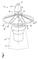
- an igniter 11 which is designed for screwing into the ogive of an artillery projectile 12, in its frustoconical lateral surface 13 on a circumferentially radially recessed storage space 14.
- This carries its rear wall 25 axially opposite, so in the direction of travel before the storage space 14, a ring 15 to which the inner circumference 31 of a coaxial in operative position circular disk-shaped braking element is hinged in the form of a flight direction against the stretchable textile screen 16.
- This textile brake element is folded in its depot and transfer position from the ring 15 forth uniformly around the projectile longitudinal axis 17 around in the storage space 14 and overlapped by a hood until it is released by the blowing off of the hood for centrifugal radial issuing in the umbrella shape ,
- Corrioliskraft in the articulation of the brake element can be selectively reduced to the ring 15
- the thus located on the inner periphery of the hollow cylinder force elements 19 are used to radially ceremoniessprengen when stored on the receptacle 18 hollow cylinder of the hood and thus disassemble this cover disassembled into defined pieces of storage space 14.
- This centrifugal force issuing of the annular disc brake screen 16 is further promoted by the fact that - the shield at least by seam seams, but optionally also by sewing reinforcements compared to the cloth surface with a defined mass accumulation 29 is equipped with the moment of inertia for To increase a rapid and stable issuing from the folded position in the final shape given from the cut in the interest of a fast-acting large, symmetrical inflow surface for maximum braking effect.
- braking screen 16 which, however, flows against its outer circumferential surface, essentially a textile structure surrounding the fastening ring 15 in the form of an annular disk.
- this is designed from the cut, under the influence of centrifugal forces not to be clamped in a substantially flat and therefore flatter end textile disc, but only up to a relatively large angle relative to the projectile axis 17, in the maximum issued state without fluttering along the Edge always the same frusto-conical geometry stable to be able to comply.
- a circular cut cloth 33 is equipped by radially extending dart so with a reduced outer circumference 32, characterized in that the clamping movement to the shape of a flat obtuse-angled hollow truncated cone is limited, by means of longitudinal generatrix of the conical surface applied reinforcing ribbons 34 on the inner circumference 31 of the forwardly pointing small base a radial distance bridging to the retaining ring 15 is hinged and rearwardly, along the outer periphery 32, with a circumferential mass accumulation 29 for reinforcement equipped with centrifugal release forces; wherein the ring 15 in the front end region of the storage space 14, temporarily slipping relative to the projectile twist, is axially clamped in the contour of the igniter 12.
Description
Die Erfindung betrifft eine Bremseinrichtung gemäß dem Oberbegriff des Anspruches 1. Eine solche Bremseinrichtung ist aus der
Vorliegender Erfindung liegt die technische Problemstellung zugrunde, eine Bremseinrichtung gattungsgemäßer Art dahingehend weiterzubilden, dass sich einerseits ein spürbar vergrößerter Bremseffekt bei andererseits stabiler Ballistik während des Initiierens der Bremseinrichtung ergibt.The present invention is based on the technical problem of developing a braking device of the generic type in such a way that, on the one hand, a noticeably increased braking effect results on the other hand in stable ballistics during the initiation of the braking device.
Dieser Aufgabenstellung liegt die Erkenntnis zugrunde, dass eine sternförmige Anordnung von radial ausklappbaren Bremssegmenten trotz der Wirbelbildungen in den Lücken zwischen den Bremssegmenten noch nicht die wünschenswerte Bremsbeiwerte zum möglichst raschen und definierten Übergang aus der ballistischen Verbringungsbahn in eine versteilerte Abstiegsbahn erbringt. Die Bremswirkung lässt sich zwar verbessern, wenn die freien Zwickel zwischen den einzelnen Bremssegmenten von spitzwinklig dreiecksförmigen Tüchern überspannt werden, die beim Verbringen aus dem Geschütz zunächst noch zusammen mit den Bremssegmenten in den Stauraum unter einer Halterungs-Haube eingefaltet sind und dann mit dem Absprengen der Haube zum fliehkraftgestützten Aufrichten freigegeben werden; aber die Kombination aus scharnierartig angelenkten Bremssegmenten und dazwischen eingespannten Textilien ist außerordentlich montageaufwendig und weist darüber hinaus den Nachteil auf, dass aufgrund der kompakten Pressung im Stauraum lokale mechanische Beanspruchungen zur bereichsweisen Beschädigung der textilen Lückenfüller führen können. Nachdem es ohnehin kritisch ist, alle diese Lückenfüller durch das Ausschwenken der mantelschalenförmigen Bremssegmente rundum gleichzeitig zu spannen, so daß keine unsymmetrischen Anströmkräfte auftreten und zu unkontrollierbarer Ablenkung aus der bisherigen Flugbahn führen können, sind derartige Störungen gar nicht mehr zu vermeiden, wenn die Dreiecktücher lokal beschädigt sind und somit in nicht vorherbestimmbaren Sektoren um die Projektilogive herum ein vom Standard abweichendes Bremsverhalten erbringen.This task is based on the finding that a star-shaped arrangement of radially expandable brake segments, despite the formation of vortices in the gaps between the brake segments, does not yet provide the desirable brake coefficients for the fastest possible and more defined transition from the ballistic transfer path to a steepened descent path. Although the braking effect can be improved if the free gussets between the individual brake segments are spanned by acute-angled triangular wipes, which are initially folded together with the brake segments in the storage space under a support hood when moving out of the gun and then with the blasting of Hood to be released for centrifugal assisted erection; but the combination of hinge-hinged brake segments and textiles clamped therebetween is extremely difficult to install and also has the disadvantage that local mechanical stresses due to the compact pressure in the storage space to the area Damage to the textile gap filler can lead. After all, it is critical to tension all these gap fillers at the same time by swinging out of the shell shell-shaped brake segments, so that no asymmetrical flow forces occur and can lead to uncontrollable distraction from the previous trajectory, such disturbances are no longer avoidable when the triangular cloths locally are damaged and thus provide non-standard braking behavior in non-predictable sectors around the projectile log.
Die oben umrissene Aufgabe wird erfindungsgemäß dadurch gelöst, daß die Kombination der im Hauptanspruch angegebenen Merkmale verwirklicht ist, wonach die bisher diskreten Bremssegmente praktisch zu einem integralen textilen Gebilde von der Form eines die Ogive umgebenden, zum flachen stumpfwinkligen Hohlkegelstumpf angestellten Kreisringes mit nach voraus weisender kleiner Basis aufgespannt werden.The above outlined object is achieved in that the combination of the features specified in the main claim is realized, according to which the previously discrete brake segments practically to an integral textile structure of the shape of an ogive surrounding the flat obtuse hollow truncated cone annealed annulus with pointing ahead smaller Base be spanned.
Zur näheren Erläuterung der Erfindung, ihrer Vorteile und Weiterbildungen wird außer auf die weiteren Ansprüche auch auf die nachstehende Beschreibung eines in der Zeichnung unter Beschränkung auf das Wesentliche stark abstrahiert aber angenähert maßstabsgerecht skizzierten bevorzugten Realisierungsbeispiels für die erfindungsgemäße Bremseinrichtung verwiesen. In der Zeichnung zeigt:
- Fig. 1
- Einen im Ogivenbereich auf ein Artillerieprojektil montierten Zünder für die Gefechtskopfauslösung, mit Darstellung eines ringtuchförmigen textilen Bremselementes im ausgestellten Zustand und
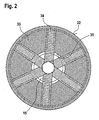
- Fig. 2
- das Bremselement als solches in Stirnansicht.
- Fig. 1
- A mounted in the Ogivenbereich on an artillery projectile detonator for the warhead activation, with representation of a ring-shaped textile brake element in the issued state and
- Fig. 2
- the brake element as such in front view.
Wie im Hauptpatent näher dargestellt, weist ein Zünder 11, der zum Einschrauben in die Ogive eines Artillerie-Projektiles 12 ausgelegt ist, in seiner kegelstumpfförmigen Mantelfläche 13 einen umlaufend radial eingesenkten Stauraum 14 auf. Dieser trägt seiner Rückwand 25 axial gegenüber, also in Flugrichtung vor dem Stauraum 14 einen Ring 15, an den der Innenumfang 31 eines in Wirkstellung koaxial kreisscheibenförmig umlaufenden Bremselementes in Form eines der Flugrichtung entgegen aufspannbaren textilen Schirmes 16 angelenkt ist. Dieses textile Bremselement ist in seiner Depot- und Verbringungsstellung vom Ring 15 her nach rückwärts gleichförmig um die Projektil-Längsachse 17 herum in den Stauraum 14 eingefaltet und von einer Haube übergriffen, bis es durch das Absprengen der Haube zum fliehkraftbedingten radialen Ausstellen in die Schirmform freigegeben wird. Damit die bei dieser radialen Ausstellbewegung unter Rotation des Projektiles 12 auftretende Corrioliskraft im Anlenkbereich des Bremselementes an den Ring 15 gezielt abgebaut werden kann, ist es zweckmäßig, bei der axialen Einspannung des Ringes 15 ein vorübergehendes Durchdrehen relativ zum Projektil 12 zuzulassen, bis der Kräfteabbau zur Beendigung dieses Schlupfes führt.As shown in detail in the main patent, an
Die den umlaufenden Stauraum 14 mit dem eingefalteten Bremselement übergreifende Haube zur Ergänzung der Kontur der Kegelmantelfläche 13 Zünders 11 im Anschluss an die Außenmantelfläche 27 des Projektiles 12 ist vorne, vor der kleinen Basis des Bremsschirmes 16, als dickwandiger Hohlzylinder ausgelegt. Daran schließt sich einstückig nach rückwärts eine dagegen sehr dünne hohlkegelstumpfförmige Wandung an. Dieser dünnwandige Bereich ist konstruktiv dafür ausgelegt, sich achsparallel bis zum Hohlzylinder vor sich erstreckender Sollbruchstellen in einzelne, dann unter dem Einfluß der Zentrifugalkraft radial vom rotierenden Stauraum 14 abhebende Schalenstücke zu zerlegen. Dafür greift wie beim Hauptpatent der Stiel einer pilzförmigen Aufnahme 18 für mehrere über den Umfang gleichförmig verteilte, radial wirkende pyrotechnische Kraftelemente 19 von vorne, der Flugrichtung also entgegen, axial durch den Hohlzylinder der Haube und durch den Anlenk-Ring 15 hindurch in eine Fassung in der mechanischen Struktur des Zünders 11 ein. Die dadurch an der Innenperipherie des Hohlzylinders gelegenen Kraftelemente 19 dienen dazu, bei Zündung den auf der Aufnahme 18 lagernden Hohlzylinder der Haube radial Aufzusprengen und damit diese Abdeckhaube in definierte Stücke zerlegt vom Stauraum 14 abheben zu lassen.The
Die radiale pyrotechnische Beanspruchung des an der Aufnahme 18 ruhenden Hohlzylinders am vorderen Ende der Verbringungshaube führt also zum Entfernen der Stauraumwandung und damit zum Freigeben des Bremsschirmes 16, der sich nun zentrifugal aus dem Stauraum 14 heraus um den Ring 15 herum als dessen kleinere Hohlkegelstumpf-Basis in eine zur Achse 17 nicht ganz orthogonale Wirkstellung ringscheibenförmig rasch und formstabil aufspannt.The radial pyrotechnic stress of resting on the
Dieses fliehkraftbedingte Ausstellen des ringscheibenförmigen Bremsschirmes 16 wird noch dadurch gefördert, daß - der Anlenkung am Ring 15 gegenüber - der Schirm wenigstens durch Saumnähte, gegebenenfalls aber auch durch Einnähen von Verstärkungen im Vergleich zur Tuchfläche mit einer definierten Massenansammlung 29 ausgerüstet ist, um das Trägheitsmoment für ein rasches und stabiles Ausstellen aus der eingefalteten Lage in die vom Schnitt her vorgegebene Endform im Interesse einer schnell wirksamen großen, symmetrischen Anströmfläche für maximale Bremswirkung zu steigern.This centrifugal force issuing of the annular
Wie in der Zeichnung skizziert handelt es sich also beim hier so genannten Bremsschirm 16, der aber gegen seine Außenmantelfläche angeströmt wird, im wesentlichen um eine den Befestigungsring 15 ringscheibenförmig umgebendes textiles Gebilde. Das ist allerdings vom Schnitt her dafür ausgelegt, unter Einfluß der Zentrifugalkräfte nicht in eine im wesentlichen ebene und daher flattergefährdete textile Scheibe aufgespannt zu werden, sondern nur bis zu einem relativ großen Winkel gegenüber der Projektilachse 17, um im maximal ausgestellten Zustand ohne Flattererscheinungen längs des Randes stets die gleiche kegelstumpfförmige Geometrie stabil einhalten zu können. Dafür ist das an sich in der Ebene kreisrund zugeschnittene Tuch 33 des Schirmes 16 mit radialen Sektorschnitten oder Nähfalten längs schmaler Ausschnitte in Umfangsrichtung so gerafft, daß der Außenumfang des Schirmes 16 in seiner kegelstumpfförmig aufgestellten Wirkstellung kleiner als der auf den Radius bezogene Kreisumfang ist. Das führt zu einem auch unter der Anströmung ringsum gleichförmig aufgebauschten, mechanisch stabilen und geometrisch definierten kegelstumpfmantelförmigen Bremsschirm 16, der in Flugrichtung orientiert ist, dessen kleine Basis also gleich bei der Aufnahme 18 mit dem Ring 15 liegt, während die große Basis von dort nach rückwärts, zum Projektil 12 hin orientiert ist.As sketched in the drawing, in the case of the so-called
Dieser breite ringscheibenförmige Bremsschirm 16 kann mit seinem Tuch 33 längs dessen Innendurchmessers unmittelbar den Ring 15 umschlingend angelenkt sein. Zweckmäßiger ist es jedoch, das Tuch 33 strahlen- oder speichenförmig mit ebenfalls textilen Verstärkungsbändern 34 zu benähen, die einerseits an den Außenumfang 32 anschließen und sich von dort radial über den Innenumfang 31 hinaus bis zum Ring 15 erstrecken, dessen Außenendurchmesser etwas kleiner als derjenige des Innumfangs 31 ist. So ist das kreisringförmige, kegelstumpfförmig angestellte Tuch 33 nur mittels der Verstärkungsbänder 34 an den Ring 15 gefesselt, was ein gleichmäßiges Ausstellen beim Auftauchen aus dem Stauraum 14 fördert und Beschädigungen des Tuches 33 beim anfängliche Durchrutschen des Ringes 15 zuverlässig vermeidet.This wide annular disc-
Um also das fliehkraftbedingt radial ausstellende textile Bremselement 16 rasch in eine auch unter Anströmungsbedingungen stets definierte, formstabile Kontur zu bringen, ist ein kreisringförmig zugeschnittenes Tuch 33 durch radial verlaufende Abnäher derart mit einem verkleinerten Außenumfang 32 ausgestattet, daß die Aufspannbewegung dadurch auf die Form eines flachen stumpfwinkligen Hohlkegelstumpfes begrenzt wird, der mittels längs Erzeugender der Kegelmantelfläche aufgebrachter Verstärkungsbänder 34 am Innenumfang 31 der in Flugrichtung nach vorne weisenden kleinen Basis einen radialen Abstand überbrückend an den Haltering 15 angelenkt ist und rückwärtig, längs des Außenumfangs 32, mit einer umlaufenden Masseansammlung 29 zur Verstärkung der zentrifugalen Ausstellkräfte ausgestattet ist; wobei der Ring 15 im vorderen Stirnbereich des Stauraumes 14, relativ zum Projektildrall vorübergehend durchrutschend, in die Kontur des Zünders 12 axial eingespannt ist.So as to rapidly bring the centrifugal force radially exhibiting
Claims (4)
- Braking device having braking elements which can be deployed radially in the fuze area of the ogive of a correctable-trajectory artillery projectile (12) under a shroud, which can be blown off, from a stowage area (14),
characterized
in that a braking element which is circumferential without any gaps and is in the form of a textile screen (16) is provided which cannot be spread out into an essentially flat textile disc because its external circumference (32) is shortened with respect to its radius, but can be deployed at the most only to a flat, obtuse-angled hollow truncated conical shape, whose small base, which points forwards in the direction of flight, is articulated at a holding ring (15) in the front area of the stowage area (14). - Braking device according to Claim 1,
characterized
in that the screen (16) is fitted with radially running reinforcing strips (34) which are looped around the holding ring (15), bridging an unobstructed radial distance between the inner circumference (31) and the holding ring (15). - Braking device according to Claim 1 or 2,
characterized
in that the holding ring (15) is clamped axially into the contour of the fuze (11) such that it can rotate with respect to the spin of the projectile (12). - Braking device according to one of the preceding claims,
characterized
in that the external circumference (32) of the screen (16) is fitted with an additional mass accumulation (29).
Applications Claiming Priority (3)
| Application Number | Priority Date | Filing Date | Title |
|---|---|---|---|
| DE10242588 | 2002-09-13 | ||
| DE2002142588 DE10242588B4 (en) | 2001-09-04 | 2002-09-13 | Braking device for a web-corrected spin-stabilized artillery projectile |
| PCT/EP2003/010021 WO2004031682A1 (en) | 2002-09-13 | 2003-09-10 | Braking device for a trajectory-correctable spin-stabilized artillery projectile |
Publications (2)
| Publication Number | Publication Date |
|---|---|
| EP1540264A1 EP1540264A1 (en) | 2005-06-15 |
| EP1540264B1 true EP1540264B1 (en) | 2010-06-09 |
Family
ID=32049157
Family Applications (1)
| Application Number | Title | Priority Date | Filing Date |
|---|---|---|---|
| EP03775150A Expired - Lifetime EP1540264B1 (en) | 2002-09-13 | 2003-09-10 | Braking device for a trajectory-correctable spin-stabilized artillery projectile |
Country Status (6)
| Country | Link |
|---|---|
| US (1) | US7347147B2 (en) |
| EP (1) | EP1540264B1 (en) |
| KR (1) | KR100676453B1 (en) |
| AU (1) | AU2003283241A1 (en) |
| DE (1) | DE50312805D1 (en) |
| WO (1) | WO2004031682A1 (en) |
Families Citing this family (9)
| Publication number | Priority date | Publication date | Assignee | Title |
|---|---|---|---|---|
| JP2005044390A (en) * | 2003-07-22 | 2005-02-17 | Tdk Corp | Manufacturing method of magnetic recording medium, stamper for magnetic recording medium, and intermediate for magnetic recording medium |
| DE102005052474B3 (en) | 2005-11-03 | 2007-07-12 | Junghans Feinwerktechnik Gmbh & Co. Kg | Spiked artillery projectile |
| US7800032B1 (en) * | 2006-11-30 | 2010-09-21 | Raytheon Company | Detachable aerodynamic missile stabilizing system |
| US9677234B2 (en) * | 2011-11-23 | 2017-06-13 | Engineered Arresting Systems Corporation | Vehicle catch systems and methods |
| SE1230014A1 (en) * | 2012-02-06 | 2013-07-23 | Bae Systems Bofors Ab | Brake panel for a spark plug or projectile |
| US9174738B1 (en) * | 2013-04-14 | 2015-11-03 | Google Inc. | Drag disk, small |
| US9849961B2 (en) * | 2015-09-23 | 2017-12-26 | Northrop Grumman Systems Corporation | High altitude balloon with a payload separation assembly |
| US20190016469A1 (en) * | 2017-07-13 | 2019-01-17 | Thomas C. Wilkes | Deceleration Apparatus |
| SE543876C2 (en) * | 2019-12-20 | 2021-08-17 | Bae Systems Bofors Ab | Brake for projectile |
Family Cites Families (10)
| Publication number | Priority date | Publication date | Assignee | Title |
|---|---|---|---|---|
| US3047259A (en) * | 1959-11-25 | 1962-07-31 | George J Tatnall | Speed brake retarding mechanism for an air-dropped store |
| US3114315A (en) * | 1961-09-26 | 1963-12-17 | William E Trump | Dive brake |
| DE3608109A1 (en) * | 1986-03-12 | 1987-09-17 | Diehl Gmbh & Co | BRAKE DEVICE FOR A SPIN-STABILIZED PROJECTILE |
| DE3643294A1 (en) * | 1986-12-18 | 1988-06-23 | Rheinmetall Gmbh | BULLET |
| DE3909902A1 (en) * | 1989-03-25 | 1990-09-27 | Diehl Gmbh & Co | BRAKE CLOTH ATTACHED TO THE BOTTOM OF A SUBMUNITION CONTAINER PROJECTILE |
| FR2660908B1 (en) * | 1990-04-13 | 1994-09-09 | Dassault Avions | AERODYNAMIC BRAKING DEVICE. |
| DE4120027C2 (en) * | 1991-06-18 | 1996-08-01 | Rheinmetall Ind Gmbh | Braking element |
| DE19824288C2 (en) * | 1998-05-29 | 2002-11-14 | Rheinmetall W & M Gmbh | artillery shell |
| DE10023345C2 (en) * | 2000-05-12 | 2002-03-28 | Diehl Munitionssysteme Gmbh | Swirl-stabilized projectile with braking device |
| DE10143312C1 (en) * | 2001-09-04 | 2003-06-18 | Diehl Munitionssysteme Gmbh | Braking device for a path-correctable spin-stabilized artillery projectile |
-
2003
- 2003-09-10 AU AU2003283241A patent/AU2003283241A1/en not_active Abandoned
- 2003-09-10 US US10/527,306 patent/US7347147B2/en active Active
- 2003-09-10 KR KR1020057004282A patent/KR100676453B1/en active IP Right Grant
- 2003-09-10 WO PCT/EP2003/010021 patent/WO2004031682A1/en not_active Application Discontinuation
- 2003-09-10 DE DE50312805T patent/DE50312805D1/en not_active Expired - Lifetime
- 2003-09-10 EP EP03775150A patent/EP1540264B1/en not_active Expired - Lifetime
Also Published As
| Publication number | Publication date |
|---|---|
| US20050258308A1 (en) | 2005-11-24 |
| AU2003283241A1 (en) | 2004-04-23 |
| KR100676453B1 (en) | 2007-01-30 |
| EP1540264A1 (en) | 2005-06-15 |
| US7347147B2 (en) | 2008-03-25 |
| DE50312805D1 (en) | 2010-07-22 |
| KR20050043953A (en) | 2005-05-11 |
| WO2004031682A1 (en) | 2004-04-15 |
Similar Documents
| Publication | Publication Date | Title |
|---|---|---|
| EP1154223B1 (en) | Spin stablised projectile provided with brake fins | |
| EP1540264B1 (en) | Braking device for a trajectory-correctable spin-stabilized artillery projectile | |
| DE69922443T2 (en) | Bursting ring for a gas turbine | |
| DE3302576C2 (en) | Fan housing with a blade break protection device for an axial gas turbine engine | |
| EP0794405B1 (en) | Method and device for dispersing a large caliber payload above a target | |
| DE3937762C2 (en) | Artillery shell submunition | |
| DE3608109C2 (en) | ||
| DE2644066A1 (en) | WING PROFILE STRUCTURE WITH BREAK-OFF EDGE | |
| DE69918162T2 (en) | Rupture protection device for radial turbines | |
| DE2117097A1 (en) | turbine | |
| DE4303076A1 (en) | Missile | |
| DE10242588B4 (en) | Braking device for a web-corrected spin-stabilized artillery projectile | |
| EP1288608B1 (en) | Braking arrangement for a spin-stabilised and trajectory-influenced artillery projectile | |
| DE2330045C2 (en) | Missile for firing and dispersing reflective material | |
| DE2452053A1 (en) | DEVICE FOR LAUNCHING ROCKET-PROPELLED AIRCRAFT | |
| DE4124960C2 (en) | Submunition with a rotating parachute | |
| DE3643294A1 (en) | BULLET | |
| EP0392192B1 (en) | Method for dispersing sub-missiles | |
| DE2429912A1 (en) | Parachute load separation system - has brake retarding projectile rotation until it overturns and releases load | |
| DE1428646A1 (en) | rocket | |
| EP0363837B1 (en) | Parachute system for a launching body | |
| DE10005414B4 (en) | Tail stabilized training projectile | |
| DE1506101C (en) | Pyrotechnic device for the rapid deployment of a parachute | |
| DE19842541C2 (en) | Stabilization strap attachment for a drop ammunition | |
| US4166416A (en) | Obturating split disc |
Legal Events
| Date | Code | Title | Description |
|---|---|---|---|
| PUAI | Public reference made under article 153(3) epc to a published international application that has entered the european phase |
Free format text: ORIGINAL CODE: 0009012 |
|
| 17P | Request for examination filed |
Effective date: 20050301 |
|
| AK | Designated contracting states |
Kind code of ref document: A1 Designated state(s): AT BE BG CH CY CZ DE DK EE ES FI FR GB GR HU IE IT LI LU MC NL PT RO SE SI SK TR |
|
| AX | Request for extension of the european patent |
Extension state: AL LT LV MK |
|
| DAX | Request for extension of the european patent (deleted) | ||
| RBV | Designated contracting states (corrected) |
Designated state(s): DE FR GB |
|
| 17Q | First examination report despatched |
Effective date: 20080222 |
|
| GRAP | Despatch of communication of intention to grant a patent |
Free format text: ORIGINAL CODE: EPIDOSNIGR1 |
|
| GRAS | Grant fee paid |
Free format text: ORIGINAL CODE: EPIDOSNIGR3 |
|
| GRAA | (expected) grant |
Free format text: ORIGINAL CODE: 0009210 |
|
| AK | Designated contracting states |
Kind code of ref document: B1 Designated state(s): DE FR GB |
|
| REF | Corresponds to: |
Ref document number: 50312805 Country of ref document: DE Date of ref document: 20100722 Kind code of ref document: P |
|
| PLBE | No opposition filed within time limit |
Free format text: ORIGINAL CODE: 0009261 |
|
| STAA | Information on the status of an ep patent application or granted ep patent |
Free format text: STATUS: NO OPPOSITION FILED WITHIN TIME LIMIT |
|
| 26N | No opposition filed |
Effective date: 20110310 |
|
| REG | Reference to a national code |
Ref country code: DE Ref legal event code: R097 Ref document number: 50312805 Country of ref document: DE Effective date: 20110309 |
|
| REG | Reference to a national code |
Ref country code: FR Ref legal event code: PLFP Year of fee payment: 14 |
|
| REG | Reference to a national code |
Ref country code: DE Ref legal event code: R081 Ref document number: 50312805 Country of ref document: DE Owner name: DIEHL DEFENCE GMBH & CO. KG, DE Free format text: FORMER OWNER: DIEHL BGT DEFENCE GMBH & CO. KG, 88662 UEBERLINGEN, DE |
|
| REG | Reference to a national code |
Ref country code: FR Ref legal event code: PLFP Year of fee payment: 15 |
|
| REG | Reference to a national code |
Ref country code: FR Ref legal event code: PLFP Year of fee payment: 16 |
|
| PGFP | Annual fee paid to national office [announced via postgrant information from national office to epo] |
Ref country code: GB Payment date: 20220920 Year of fee payment: 20 |
|
| PGFP | Annual fee paid to national office [announced via postgrant information from national office to epo] |
Ref country code: FR Payment date: 20220922 Year of fee payment: 20 |
|
| PGFP | Annual fee paid to national office [announced via postgrant information from national office to epo] |
Ref country code: DE Payment date: 20221123 Year of fee payment: 20 |
|
| REG | Reference to a national code |
Ref country code: DE Ref legal event code: R071 Ref document number: 50312805 Country of ref document: DE |
|
| REG | Reference to a national code |
Ref country code: GB Ref legal event code: PE20 Expiry date: 20230909 |
|
| PG25 | Lapsed in a contracting state [announced via postgrant information from national office to epo] |
Ref country code: GB Free format text: LAPSE BECAUSE OF EXPIRATION OF PROTECTION Effective date: 20230909 |