EP1538884B1 - Flüssigkühlsystem für ein elektronisches Gerät - Google Patents
Flüssigkühlsystem für ein elektronisches Gerät Download PDFInfo
- Publication number
- EP1538884B1 EP1538884B1 EP04005163A EP04005163A EP1538884B1 EP 1538884 B1 EP1538884 B1 EP 1538884B1 EP 04005163 A EP04005163 A EP 04005163A EP 04005163 A EP04005163 A EP 04005163A EP 1538884 B1 EP1538884 B1 EP 1538884B1
- Authority
- EP
- European Patent Office
- Prior art keywords
- lamination
- plate
- liquid
- heat
- plates
- Prior art date
- Legal status (The legal status is an assumption and is not a legal conclusion. Google has not performed a legal analysis and makes no representation as to the accuracy of the status listed.)
- Expired - Lifetime
Links
Images


Classifications
-
- E—FIXED CONSTRUCTIONS
- E02—HYDRAULIC ENGINEERING; FOUNDATIONS; SOIL SHIFTING
- E02D—FOUNDATIONS; EXCAVATIONS; EMBANKMENTS; UNDERGROUND OR UNDERWATER STRUCTURES
- E02D29/00—Independent underground or underwater structures; Retaining walls
- E02D29/02—Retaining or protecting walls
- E02D29/0225—Retaining or protecting walls comprising retention means in the backfill
- E02D29/0241—Retaining or protecting walls comprising retention means in the backfill the retention means being reinforced earth elements
-
- F—MECHANICAL ENGINEERING; LIGHTING; HEATING; WEAPONS; BLASTING
- F28—HEAT EXCHANGE IN GENERAL
- F28F—DETAILS OF HEAT-EXCHANGE AND HEAT-TRANSFER APPARATUS, OF GENERAL APPLICATION
- F28F3/00—Plate-like or laminated elements; Assemblies of plate-like or laminated elements
- F28F3/12—Elements constructed in the shape of a hollow panel, e.g. with channels
-
- E—FIXED CONSTRUCTIONS
- E02—HYDRAULIC ENGINEERING; FOUNDATIONS; SOIL SHIFTING
- E02D—FOUNDATIONS; EXCAVATIONS; EMBANKMENTS; UNDERGROUND OR UNDERWATER STRUCTURES
- E02D29/00—Independent underground or underwater structures; Retaining walls
- E02D29/02—Retaining or protecting walls
- E02D29/025—Retaining or protecting walls made up of similar modular elements stacked without mortar
-
- E—FIXED CONSTRUCTIONS
- E02—HYDRAULIC ENGINEERING; FOUNDATIONS; SOIL SHIFTING
- E02D—FOUNDATIONS; EXCAVATIONS; EMBANKMENTS; UNDERGROUND OR UNDERWATER STRUCTURES
- E02D29/00—Independent underground or underwater structures; Retaining walls
- E02D29/02—Retaining or protecting walls
- E02D29/0258—Retaining or protecting walls characterised by constructional features
- E02D29/0266—Retaining or protecting walls characterised by constructional features made up of preformed elements
-
- G—PHYSICS
- G06—COMPUTING OR CALCULATING; COUNTING
- G06F—ELECTRIC DIGITAL DATA PROCESSING
- G06F1/00—Details not covered by groups G06F3/00 - G06F13/00 and G06F21/00
- G06F1/16—Constructional details or arrangements
- G06F1/20—Cooling means
-
- H—ELECTRICITY
- H01—ELECTRIC ELEMENTS
- H01L—SEMICONDUCTOR DEVICES NOT COVERED BY CLASS H10
- H01L23/00—Details of semiconductor or other solid state devices
- H01L23/34—Arrangements for cooling, heating, ventilating or temperature compensation ; Temperature sensing arrangements
- H01L23/46—Arrangements for cooling, heating, ventilating or temperature compensation ; Temperature sensing arrangements involving the transfer of heat by flowing fluids
- H01L23/473—Arrangements for cooling, heating, ventilating or temperature compensation ; Temperature sensing arrangements involving the transfer of heat by flowing fluids by flowing liquids
-
- E—FIXED CONSTRUCTIONS
- E02—HYDRAULIC ENGINEERING; FOUNDATIONS; SOIL SHIFTING
- E02D—FOUNDATIONS; EXCAVATIONS; EMBANKMENTS; UNDERGROUND OR UNDERWATER STRUCTURES
- E02D2600/00—Miscellaneous
- E02D2600/20—Miscellaneous comprising details of connection between elements
-
- E—FIXED CONSTRUCTIONS
- E02—HYDRAULIC ENGINEERING; FOUNDATIONS; SOIL SHIFTING
- E02D—FOUNDATIONS; EXCAVATIONS; EMBANKMENTS; UNDERGROUND OR UNDERWATER STRUCTURES
- E02D2600/00—Miscellaneous
- E02D2600/40—Miscellaneous comprising stabilising elements
-
- G—PHYSICS
- G06—COMPUTING OR CALCULATING; COUNTING
- G06F—ELECTRIC DIGITAL DATA PROCESSING
- G06F2200/00—Indexing scheme relating to G06F1/04 - G06F1/32
- G06F2200/20—Indexing scheme relating to G06F1/20
- G06F2200/201—Cooling arrangements using cooling fluid
-
- H—ELECTRICITY
- H01—ELECTRIC ELEMENTS
- H01L—SEMICONDUCTOR DEVICES NOT COVERED BY CLASS H10
- H01L2924/00—Indexing scheme for arrangements or methods for connecting or disconnecting semiconductor or solid-state bodies as covered by H01L24/00
- H01L2924/0001—Technical content checked by a classifier
- H01L2924/0002—Not covered by any one of groups H01L24/00, H01L24/00 and H01L2224/00
-
- H—ELECTRICITY
- H01—ELECTRIC ELEMENTS
- H01L—SEMICONDUCTOR DEVICES NOT COVERED BY CLASS H10
- H01L2924/00—Indexing scheme for arrangements or methods for connecting or disconnecting semiconductor or solid-state bodies as covered by H01L24/00
- H01L2924/30—Technical effects
- H01L2924/301—Electrical effects
- H01L2924/3011—Impedance
Definitions
- the present invention relates to an electronic apparatus having a cooling system of a heat-generation element thereof.
- a purpose of that invention disclosed in the patent document 3 is to prevent a heat sink of lamination plate type from generating the defects therein, and also to obtain an improvement on reliability and cooling capacity of an apparatus or equipment, by installing that heat sink therein, as was described in the column "Problems to be Solved" in the specification thereof.
- a pair of end plates are provide, for holding a flow passage plate and a communicating plate from both sides thereof, and further they are disposed at positions corresponding to the flow passage of high temperature and that of low temperature, thereby achieving an averaging of temperature.
- US 2002/0135979 Al shows a two phase cooling module for electronic components which includes a plurality of layered laminate sheets interposed between a first cover and second cover.
- the layered laminate sheets define walls of a vapor/liquid cavity.
- a support member, non-integral with the plurality of layered laminate sheets, is operatively connected to at least one of the first and second covers.
- a method of making a two phase module includes forming the first cover, second cover, and window shaped laminate sheets by punching sheets of aluminum.
- the method also includes forming alignment apertures in each of the plurality of window-shaped laminate sheets, stacking the plurality of window-shaped laminate sheets on a cover using the alignment apertures, and placing the other cover on the resulting stack of window shaped laminate sheets to form an enclosure assembly defining the vapor/liquid cavity. Once the cavity is formed, the method includes brazing the enclosure assembly to attach the aluminum sheets and the support member together.
- an object according to the prevent invention is to provide an electronic apparatus having a liquid cooling jacket and a liquid cooling system, for use in cooling thereof, with aiming a promotion or enhancement of heat transfer as well as thermal conductivity of a flow passage itself.
- a liquid cooling system comprising: a heat-receiving element, being thermally connected with a heat-generation part; a pump for transporting a liquid to said heat-receiving element; and a radiator for receiving heat from said heat-generation part with an aid of said pump, and for radiating heat of the liquid
- said heat-receiving element is made up with at least one lamination plate, being formed through punching process, and said at least one lamination plate comprises a flow passage, within which the liquid communicates and is provided with a cooling fin surface area
- said at least one lamination plate includes a plurality of first lamination plates having at least one hole at a central portion thereof, and a plurality of second lamination plates having an opened cut-out portion at one end thereof and a hole at other thereof, and said first and second lamination plates are piled up alternately, thereby forming a lamination group of an inlet side of the liquid and another lamination group of an outlet
- said lamination plate is made up with metal thin-plates, each having a plural number of holes in a longitudinal direction thereof, being shifted into one side in the longitudinal direction with respect to a central portion thereof, being piled up one by one, while reversing the metal thin-plate upside down.
- said lamination plate is made up with metal thin-plates, each having a zigzagging one (1) piece of hole, being shifted into a one side with respect to a central portion thereof, being piled up one by one, while reversing the metal thin-plate upside down.
- said lamination plate is made up with two (2) pieces of metal plates being laminated vertically, and an upper metal plate of those two (2) metal plates laminated vertically has a one (1) piece of zigzagging groove and a hangover portion, which is formed through extrusion forming within an inside of said groove, and said upper metal plate is fixed on a plate-like lower metal plate, putting a sealing member therebetween.
- a liquid cooling system comprising: a heat-receiving element, being thermally connected with a heat-generation part; a pump for transporting a liquid to said heat-receiving element; and a radiator for receiving heat from said heat-generation part with an aid of said pump, and for radiating heat of the liquid, wherein: said heat-receiving element is made up with a lamination plate, being formed through punching process, and said lamination plate comprises a flow passage, within which the liquid communicates and are provided a plural number of fins, and further said pump and said radiator are connected with said heat-receiving member through conduits.
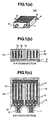
- Figs. 1(a) to 1(c) are views, including a perspective view of a liquid cooling jacket applying the first embodiment therein and the cross-section views of each part thereof.
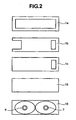
- Fig. 2 is a front view for showing the configuration of a lamination plates, building up the liquid cooling jacket shown in Figs. 1(a) to 1(c) .
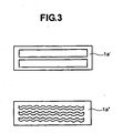
- Fig. 3 is a view corresponding to Fig. 2 mentioned above, for explaining a variation of the lamination plates.
- the liquid cooling jacket 100 is made up by bonding lamination plates 1a, 1b and 1c made from a thin plate of a metal having superior heat conductivity, such as, copper, for example, which are formed through the punching process (the configurations thereof will be explained in more details, by referring to Fig. 2 ), being piled up in the direction of thickness thereof for an each piece thereof.
- a metal having superior heat conductivity such as, copper, for example
- flow passages 8 of a cooling liquid Within the portion of openings of the lamination plates 1a, 1b and 1c are defined flow passages 8 of a cooling liquid.
- On both ends of the lamination plates 1a, 1b and 1c are attached side end plates 15.
- an end plate 16 is attached thereto. This end plate 16 defines a portion where an inlet portion 6 and an outlet portion 7 are formed for the cooling liquid.
- This liquid cooling jacket 100 is thermally connected with a semiconductor module 5, through a heat conduction member 4.
- the cooling liquid flows within the flow passage 8 defined between the lamination plates 1a and 1b; therefore, the lamination plates 1b has a kind of a cooling fin of the function thereof.
- the lamination plates 1a and 1b With such the structure, it is very easy to make the lamination plates 1a and 1b being thin in the thickness thereof, and therefore a large heat conductive area can be maintained therewith.
- the lamination plates 1a and 1b reaches up to the position in contact with the heat conductionmember 4, it is possible to eliminate an ill influence upon the heat transmission in the direction perpendicular to the base surface of the brazing material having the low heat conductivity thereof. For this reason, it is possible to obtain a low inner thermal resistance corresponding to that, which can obtained through the cutting process of forming a one body taking a high manufacturing cost thereof; therefore, it is possible to obtain very preferable cooling capacity for the sake of a semiconductor module 5.
- the liquid cooling jacket 100 is, basically, made up with only one (1) kind of the lamination plate 1 punched out, and it includes no process therein in need of man-hour, such as, needed in the cutting process, for example; therefore there is a merit that the cost can be reduced down, greatly, which is necessary for manufacturing and processing thereof, comparing to that of the conventional art. It is also possible to keep the thickness of the liquid cooling jacket 100 to be thin in a ratio to the heat conduction area obtained therefrom.
- the lamination plate 1a is punched out to be square in the shape thereof, and is put into between the respective lamination plates 1b piled up in a plural number thereof, so as to form a spacer between the lamination plates 1b.
- This lamination plates 1b are cut out at a portion opposing to the inlet portion 6 thereof, and this cut-out portion defines an enter portion for a liquid.
- a portion opposing to this cut-out portion is punched out to be also square in the shape thereof.
- This punched-out portion defines a passage, through which the liquid moves in the horizontal direction.
- this lamination plate 1b has a large contact area with the cooling liquid, therefore it has a function of, such as, a kind of a cooling fin.
- the lamination plate 1c is partitioning the lamination plates 1a and 1b in the central portion thereof, so that it divides them into a group of the lamination plates 1a and 1b opposing to the inlet portion 6 and a group of the lamination plates 1a and 1b opposing to the outlet portion 7.
- the liquid cooling jacket 100 which is built up with such the lamination plates 1a, 1b and 1c, is sealed up on both sides thereof, with an aid of the side end plates 15.
- the cut-out portion of the lamination plate 1b defines the inlet portion and the outlet portion of the cooling liquid, and therefore an end plate 16, on which the inlet portion 6 and the outlet portion 7 are formed, is attached thereto, so that it covers the cut-out portion.
- the passages of the cooling liquid is divided into the vertical direction within the lamination plate 1a'.
- the passages of the cooling liquid, being divided into the vertical direction in a plural number, are further formed in a waveform-like in the shape thereof, within the lamination plate 1a".
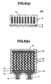
- Fig. 4 (a) is a view of showing the liquid cooling jacket, according to a second embodiment, corresponding to that shown in Fig. 1 mentioned above.
- Fig. 4 (b) is a cross-section view of the liquid cooling jacket, in particular, in a case that it is made up with piling up the lamination plates.
- lamination plates 1e are piled up in the depth direction thereof. Moreover, on this lamination plates 1e, a plural number of holes, being also formed through the punching process, are shifted in one (1) direction (in the example shown in Fig. 4 (a) , being shifted into the left-hand side), as a whole thereof. And, in the present embodiment, those lamination plates 1e are piled up, being turned upside down with an each piece thereof.
- the flow passage is meandered or zigzagged around.
- a main body of the liquid cooling jacket 100 is formed, through brazing the lamination plates 1e and 1e' after being piled up, as a whole thereof, and thereafter, the inlet portion 6 and the outlet portion 7 for the cooling liquid are attached thereon.
- the main body and the inlet portion 6 and the outlet portion 7 for the cooling liquid may be formed in one body, also through the brazing.
- a lower surface of the liquid cooling jacket 100 is connected with an upper surface of the semiconductor module 5, thermally, through a heat-conductive material having softness.
- the cooling liquid flows within the inside of the flow passage 8 defined by the lamination plates 1e and 1e'.
- the large number of overhand portions 14 functions as a cooling fin, and also it bring the flow of the cooling liquid to be complex, so as to promotes mixture thereof, therefore, it is possible to obtain a preferable cooling capacity or performance.
- the lamination plates 1 reaches up to the portion of a fin base in contact with the heat-conductive member 4, therefore it is possible to eliminate the ill influence caused upon the heat transmission in the direction perpendicular to the base surface, due to the fact the brazing material has the heat conductivity lower than that of the fin material, comparing thereto. Accordingly, the inner thermal resistance can be obtained; being worth to that which can be obtained by a member of one (1) body, taking much cost for manufacturing thereof.
- the liquid cooling jacket 100 basically, is built up with only one (1) kind of the lamination plate 1 punched out, including no such process in need of man-hour as needed in the cutting process; therefore, it has a merit that the cost necessary for manufacturing and for processing thereof can be reduced down, comparing to that in relation to the conventional arts. And, also, it is possible to maintain the liquid cooling jacket 100 to be thin in the thickness thereof.
- Fig. 5 is a view for showing the lamination plates to be applied according to the second embodiment, in which a shape of the hole is altered.
- the position of the pouching treated on the each lamination plate 1 is shifted a little bit from the central axis thereof, as was shown in Fig. 4 mentioned above, and it is piled up reversing upside down, and then the flow passage 8 comes to be complex, much more, and therefore the heat conductivity upon the surface of the flow passage 8 can be increased up to be higher.
- Fig. 6 (a) is the cross-sectional view of the liquid cooling jacket, according to a third embodiment.
- Fig. 6(b) is the cross-sectional view of the plates being piled up.
- Fig. 6(a) the lamination plates 1 and 1', in each of which the holes are formed in zigzagged manner (or, "S"-like shape) through the punching process, are piled up, one by one, each being reversed upside down. Dotted line in the figure depicts the lamination plates 1' being piled up after being reversed upside down. By means of those zigzag-shaped holes, there is made up the flow passage 8 for the cooling liquid.
- the main body of the liquid cooling jacket 100 is built up, through brazing the lamination plates 1 and 1', the upper end plate 2, and the lower end plate 3, as a whole, after filing them up in layers, and thereafter are attached with the inlet portion 6 and the outlet portion 7 for the cooling liquid thereon.
- a lower surface of the liquid cooling jacket 100 is connected with an upper surface of the semiconductor module 5, thermally, through a heat-conductive material having softness.
- the cooling liquid flows within the flow passage 8, which is defined between the upper end plate 2 and the lower end plate 3.
- the large number of hangover portions 14 are defined within the flow passage 8 so as to function as the cooling fins; therefore, it is possible to obtain a heat transfer area being large in the ratio of the thickness thereof, thereby obtaining a preferable cooling capacity or performance.
- the liquid cooling jacket 100 basically, is built up with only one (1) kind of the lamination plate 1 punched out, including no such process in need of man-hour as needed in the cutting process; therefore, it has a merit that the cost necessary manufacturing and process ingthereof can be reduced down, comparing to that in relation to the conventional arts. And, it is also possible to maintain the liquid cooling jacket 100 to be thin in the thickness thereof.
- Fig. 7(a) is an upper view of the liquid cooling jacket, according to a fourth embodiment.
- Fig. 7 (b) is the cross-sectional view of the liquid cooling jacket, according to the fourth embodiment.
- the liquid cooling jacket 100 is made up with two (2) pieces of plates, and basically, it is made up with an upper lamination plate 9, which is formed through a press process, and a plate-like lower layer plate 10.
- the upper lamination plate 9 is formed the flow passage 8 in a zigzag-like manner (or "S"-like shaped) through extrusion forming obtained by the press process, and further in this extrusion forming portion are formed a plural number of concave portions 13.
- the cooling liquid flows within the flow passage 8 defined between the upper lamination plate 9 and the lower lamination plate 10.
- the cooling liquid repeats meandering therein, thereby being enhanced or promoted on the mixing-up thereof.
- the flow passage 8 is flat and thin in the shape, and also with provision of the large number of recesses 13 thereon, it is possible to obtain a preferable heat conducting capacity or performance.
- the liquid cooling jacket 100 since it includes no such process in need of man-hour as is needed in the cutting process, and further there is no necessity of the process for forming a sealing against leakage of liquid therethrough, such as, the brazing, therefore it brings about a merit that the costs needed for manufacturing and processing can be reduced down, greatly, comparing to the conventional technology. And, also, the thickness of the liquid cooling jacket 100 can be kept to be very thin in the thickness thereof.
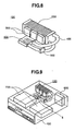
- Fig. 8 is a perspective view of a liquid cooling system, according to a fifth embodiment.
- a liquid cooling system 120 is built up with a pump 500, a radiator 200, a liquid cooling jacket 100 and a fan 300 for use of cooling down the radiator, and also pipe 400, etc.
- the liquid cooling jacket which was explained in either one of the embodiments; i.e., from the embodiment 1 to embodiment 4.
- Fig. 9 is a perspective view of an electronic apparatus installing the liquid cooling system shown in Fig. 8 mentioned above.
- the radiator 200 and the fan 300 for use of cooling of the radiator are disposed at the most downstream side within a housing 150 of the electronic apparatus.
- the thermal resistance in the liquid cooling jacket 100 which is made up through the conventional manufacturing method, such as, the extrusion forming, for example, comes to be larger than that in the radiator 200.
- the high-performances or capacity of the radiator cannot be results into an increase of heat radiation, directly, by means of the radiator 200 itself, seeing from the system, as a whole; therefore it is impossible to reach the remarkable small-sizing thereof.
- the liquid cooling jacket 100 is low on the costs thereof and also in the thermal resistance therein; therefore, an effect of high-performances or capacity of the radiator 200 gives an influence upon an increase of the heat radiation capacity or performance of the radiator 200, directly, seeing from a viewpoint of the thermal balance upon the entirety of the liquid cooling system 120. For this, it is possible to make the radiator 200 to be small in sized thereof, greatly.
- the heat removed from the semiconductor module 5 having high heat-generation is discharged from the radiator 200 into an inside of the housing 150, however it faces onto an exit portion, it goes into the atmosphere as it is, but remaining within the housing 150. For this reason, the flow within the hous ing comes to be very smooth, thereby maintaining the cooling capacity or performance to be preferable, extremely.
- the fan 300 for use of cooling the radiator also carries out the role of the discharge fan for the entirety of an inside of the housing 150, it distributes to the cooling of the other parts 700, too.
- the liquid cooling system is installed into a main body of the personal computer, for example, as is shown in Fig. 9 mentioned above, however since the liquid cooling system is compact in the sized as is shown in Fig. 8 mentioned above, therefore the field applicable of thereof is very wide, including the equipments and apparatus, which installs the semiconductor element having heat-generation therein, such as, a plasma television, a game machine, or a liquid crystal projector, etc.
- the lamination plates since it is very easy to form the lamination plates to be very thin in the thickness thereof, therefore it is possible to keep a large area for achieving the heat conduction therethrough. Also, the inner thermal resistance is very low, in respect to the heat transmission into the direction perpendicular to the base surface. Due to those effects, it is possible to obtain the cooling capacitor or performance thereof, being very preferable.
Landscapes
- Engineering & Computer Science (AREA)
- General Engineering & Computer Science (AREA)
- Physics & Mathematics (AREA)
- General Physics & Mathematics (AREA)
- Theoretical Computer Science (AREA)
- Environmental & Geological Engineering (AREA)
- Life Sciences & Earth Sciences (AREA)
- General Life Sciences & Earth Sciences (AREA)
- Mining & Mineral Resources (AREA)
- Paleontology (AREA)
- Civil Engineering (AREA)
- Structural Engineering (AREA)
- Thermal Sciences (AREA)
- Human Computer Interaction (AREA)
- Mechanical Engineering (AREA)
- Condensed Matter Physics & Semiconductors (AREA)
- Computer Hardware Design (AREA)
- Microelectronics & Electronic Packaging (AREA)
- Power Engineering (AREA)
- Cooling Or The Like Of Electrical Apparatus (AREA)
- Cooling Or The Like Of Semiconductors Or Solid State Devices (AREA)
Claims (6)
- Flüssigkeitskühlsystem mit:einem Wärme aufnehmenden Element (100), das mit einem Wärmeerzeugungsteil (5) thermisch verbunden ist;einer Pumpe (500) zum Transportieren einer Flüssigkeit zu dem Wärme aufnehmenden Element (100); undeinem Kühlkörper (200) zum Aufnehmen von Wärme von dem Wärmeerzeugungsteil mit Hilfe der Pumpe (500) und zum Abstrahlen von Wärme der Flüssigkeit,
dadurch gekennzeichnet, dassdas Wärme aufnehmende Element (100) mit zumindest einer Laminierungsplatte (1), die durch einen Stanzvorgang ausgebildet ist, hergestellt ist und die zumindest eine Laminierungsplatte (1) einen Strömungsdurchgang (8) umfasst, in welchem die Flüssigkeit mit einem Kühllamellen-Oberflächenbereich in Verbindung steht und mit diesem versehen ist; und dadurch, dassdie zumindest eine Laminierungsplatte (1) mehrere erste Laminierungsplatten (1a), die in einem zentralen Abschnitt zumindest ein Loch aufweisen, und mehrere zweite Laminierungsplatten (1b) beinhaltet, die an einem Ende einen geöffneten ausgeschnittenen Abschnitt und an dem anderen Ende ein Loch aufweisen, und dadurch, dassdie ersten Laminierungsplatten (1a) und zweiten Laminierungsplatten (1b) abwechselnd aufgestapelt sind, wodurch sie eine Laminierungsgruppe einer Einlassseite der Flüssigkeit und eine andere Laminierungsgruppe einer Auslassseite der Flüssigkeit bilden. - Flüssigkeitskühlsystem nach Anspruch 1, wobei: die Laminierungsplatte (1e) Metalldünnbleche einschließt, die jeweils mehrere Löcher in ihrer Längsrichtung aufweisen, wobei sie auf eine Seite in der Längsrichtung in Bezug auf ihren zentralen Abschnitt verschoben und eine nach der anderen aufgestapelt sind, während das Metalldünnblech mit der Oberseite nach unten umgedreht ist.
- Flüssigkeitskühlsystem nach Anspruch 1, wobei: die Laminierungsplatte (1f) Metalldünnbleche einschließt, die jeweils ein Stück Loch in Zickzackform aufweisen, die auf eine Seite in der Längsrichtung in Bezug auf ihren zentralen Abschnitt verschoben und eine nach der anderen aufgestapelt sind, während das Metalldünnblech mit der Oberseite nach unten umgedreht ist.
- Flüssigkeitskühlsystem nach Anspruch 1, wobei: die Laminierungsplatte mit zwei Stück Metallblechen, die vertikal laminiert sind, hergestellt ist, und ein oberes Metallblech (9) jener vertikal laminierten zwei Metallbleche ein (1) Stück Nut in Zickzackform und einen Überhangabschnitt aufweist, der durch eine sich im Inneren der Nut bildende Extrusion gebildet ist, und das obere Metallblech (9) an einem plattenartigen unteren Metallblech (10) befestigt ist, wobei ein Abdichtungselement dazwischengefügt ist.
- Flüssigkeitskühlsystem nach Anspruch 1, wobei die Pumpe (500) und der Kühlkörper (200) durch Leitungen mit dem Wärme aufnehmenden Element verbunden sind.
- Flüssigkeitskühlsystem nach Anspruch 5, wobei: an dem Kühlkörper (200) eine Lamelle angebracht ist.
Applications Claiming Priority (2)
| Application Number | Priority Date | Filing Date | Title |
|---|---|---|---|
| JP2003402369 | 2003-12-02 | ||
| JP2003402369A JP2005166855A (ja) | 2003-12-02 | 2003-12-02 | 電子機器 |
Publications (3)
| Publication Number | Publication Date |
|---|---|
| EP1538884A2 EP1538884A2 (de) | 2005-06-08 |
| EP1538884A3 EP1538884A3 (de) | 2005-10-12 |
| EP1538884B1 true EP1538884B1 (de) | 2010-05-26 |
Family
ID=34463949
Family Applications (1)
| Application Number | Title | Priority Date | Filing Date |
|---|---|---|---|
| EP04005163A Expired - Lifetime EP1538884B1 (de) | 2003-12-02 | 2004-03-04 | Flüssigkühlsystem für ein elektronisches Gerät |
Country Status (7)
| Country | Link |
|---|---|
| US (1) | US7044198B2 (de) |
| EP (1) | EP1538884B1 (de) |
| JP (1) | JP2005166855A (de) |
| KR (1) | KR100612810B1 (de) |
| CN (1) | CN100386872C (de) |
| DE (1) | DE602004027341D1 (de) |
| TW (1) | TWI255025B (de) |
Families Citing this family (44)
| Publication number | Priority date | Publication date | Assignee | Title |
|---|---|---|---|---|
| WO2006010822A2 (fr) * | 2004-06-24 | 2006-02-02 | TECHNOLOGIES DE L'ECHANGE THERMIQUE Société Anonyme Simplifiée | Dispositifs de refroidissement perfectionnes pour applications diverses |
| FR2880107B1 (fr) * | 2004-12-27 | 2007-05-11 | Technologies De L Echange Ther | Perfectionnements aux refroidisseurs a eau pour microprocesseurs |
| US7327571B2 (en) * | 2005-09-06 | 2008-02-05 | Hewlett-Packard Development Company, L.P. | Thermal load balancing systems and methods |
| JP4682775B2 (ja) * | 2005-09-27 | 2011-05-11 | セイコーエプソン株式会社 | マイクロチャンネル構造体、熱交換システム及び電子機器 |
| JP2007127398A (ja) | 2005-10-05 | 2007-05-24 | Seiko Epson Corp | 熱交換器、熱交換器の製造方法、液冷システム、光源装置、プロジェクタ、電子デバイスユニット、電子機器 |
| JP4449894B2 (ja) | 2005-12-16 | 2010-04-14 | セイコーエプソン株式会社 | 熱交換器、光源装置、プロジェクタおよび電子機器 |
| JP4645472B2 (ja) * | 2006-02-21 | 2011-03-09 | セイコーエプソン株式会社 | 流体冷却装置、および電子機器 |
| US7537047B2 (en) | 2006-03-23 | 2009-05-26 | Foxconn Technology Co., Ltd. | Liquid-cooling heat sink |
| CN100584169C (zh) * | 2006-04-21 | 2010-01-20 | 富准精密工业(深圳)有限公司 | 液冷散热装置 |
| JP2008027374A (ja) * | 2006-07-25 | 2008-02-07 | Fujitsu Ltd | 液冷ユニット用受熱器および液冷ユニット並びに電子機器 |
| JP5133531B2 (ja) * | 2006-07-25 | 2013-01-30 | 富士通株式会社 | 液冷ユニット用熱交換器および液冷ユニット並びに電子機器 |
| JP5148079B2 (ja) * | 2006-07-25 | 2013-02-20 | 富士通株式会社 | 液冷ユニット用熱交換器および液冷ユニット並びに電子機器 |
| JP5283836B2 (ja) | 2006-07-25 | 2013-09-04 | 富士通株式会社 | 液冷ユニット用受熱器および液冷ユニット並びに電子機器 |
| JP4781929B2 (ja) | 2006-07-25 | 2011-09-28 | 富士通株式会社 | 電子機器 |
| JP4842040B2 (ja) | 2006-07-25 | 2011-12-21 | 富士通株式会社 | 電子機器 |
| JP2008027370A (ja) | 2006-07-25 | 2008-02-07 | Fujitsu Ltd | 電子機器 |
| JP5005314B2 (ja) * | 2006-10-17 | 2012-08-22 | 株式会社ティラド | 水冷ヒートシンクおよびその製造方法 |
| US9496200B2 (en) | 2011-07-27 | 2016-11-15 | Coolit Systems, Inc. | Modular heat-transfer systems |
| US8746330B2 (en) | 2007-08-09 | 2014-06-10 | Coolit Systems Inc. | Fluid heat exchanger configured to provide a split flow |
| US9943014B2 (en) | 2013-03-15 | 2018-04-10 | Coolit Systems, Inc. | Manifolded heat exchangers and related systems |
| US9453691B2 (en) | 2007-08-09 | 2016-09-27 | Coolit Systems, Inc. | Fluid heat exchange systems |
| CN101610664B (zh) * | 2008-06-20 | 2014-05-14 | 萨帕铝型材(上海)有限公司 | 液体冷却器及其制造方法 |
| JP2011017516A (ja) * | 2009-07-10 | 2011-01-27 | Mitsubishi Electric Corp | プレート積層型冷却装置及びその製造方法 |
| JP5259559B2 (ja) * | 2009-11-30 | 2013-08-07 | 株式会社ティラド | ヒートシンク |
| JP5916603B2 (ja) * | 2010-04-28 | 2016-05-11 | 株式会社豊田自動織機 | 放熱装置および半導体装置 |
| EP2582213B1 (de) * | 2010-06-09 | 2021-01-20 | Kyocera Corporation | Flusskanalelement, wärmetauscher damit und vorrichtung mit elektronischen komponenten |
| CN102647884B (zh) * | 2011-02-17 | 2015-03-18 | 北汽福田汽车股份有限公司 | 散热器及其散热水道系统结构 |
| JP6005930B2 (ja) * | 2011-07-28 | 2016-10-12 | 京セラ株式会社 | 流路部材、これを用いた熱交換器および電子部品装置ならびに半導体製造装置 |
| US10365667B2 (en) | 2011-08-11 | 2019-07-30 | Coolit Systems, Inc. | Flow-path controllers and related systems |
| WO2014141162A1 (en) | 2013-03-15 | 2014-09-18 | Coolit Systems, Inc. | Sensors, multiplexed communication techniques, and related systems |
| US20130058043A1 (en) * | 2011-09-03 | 2013-03-07 | Weiss-Aug Co. Inc | Heat sink with a stack of metal layers having channels therein |
| US9275931B2 (en) * | 2012-01-12 | 2016-03-01 | Huang-Han Chen | Heat dissipating module |
| JP5901343B2 (ja) * | 2012-02-24 | 2016-04-06 | 三菱電機株式会社 | 冷却器及び冷却装置 |
| US12366870B2 (en) | 2013-03-15 | 2025-07-22 | Coolit Systems, Inc. | Flow-path controllers and related systems |
| KR101524939B1 (ko) * | 2013-11-06 | 2015-06-02 | 주식회사 동양매직 | 발열체 냉각을 위한 수냉식 워터재킷 및 이를 포함하는 냉각탱크 |
| WO2017098640A1 (ja) * | 2015-12-10 | 2017-06-15 | 株式会社日立製作所 | 造形物および電子機器ならびに造形方法 |
| US10251306B2 (en) * | 2016-09-26 | 2019-04-02 | Asia Vital Components Co., Ltd. | Water cooling heat dissipation structure |
| CN106711110B (zh) * | 2017-03-19 | 2019-05-17 | 北京工业大学 | 一种用于大功率串联igbt的风冷水冷混合散热模组 |
| US11662037B2 (en) | 2019-01-18 | 2023-05-30 | Coolit Systems, Inc. | Fluid flow control valve for fluid flow systems, and methods |
| US11473860B2 (en) | 2019-04-25 | 2022-10-18 | Coolit Systems, Inc. | Cooling module with leak detector and related systems |
| WO2021229365A1 (en) | 2020-05-11 | 2021-11-18 | Coolit Systems, Inc. | Liquid pumping units, and related systems and methods |
| US11725886B2 (en) | 2021-05-20 | 2023-08-15 | Coolit Systems, Inc. | Modular fluid heat exchange systems |
| US12200914B2 (en) | 2022-01-24 | 2025-01-14 | Coolit Systems, Inc. | Smart components, systems and methods for transferring heat |
| KR102449766B1 (ko) * | 2022-03-18 | 2022-10-04 | 덕양산업 주식회사 | 배터리모듈용 냉각플레이트 |
Family Cites Families (19)
| Publication number | Priority date | Publication date | Assignee | Title |
|---|---|---|---|---|
| US4468717A (en) * | 1982-06-09 | 1984-08-28 | Sperry Corporation | Apparatus for cooling integrated circuit chips |
| CA1227886A (en) * | 1984-01-26 | 1987-10-06 | Haruhiko Yamamoto | Liquid-cooling module system for electronic circuit components |
| US4561040A (en) * | 1984-07-12 | 1985-12-24 | Ibm Corporation | Cooling system for VLSI circuit chips |
| US4705102A (en) * | 1985-12-13 | 1987-11-10 | Fuji Electric Company, Ltd. | Boiling refrigerant-type cooling system |
| US4910642A (en) * | 1988-12-05 | 1990-03-20 | Sundstrand Corporation | Coolant activated contact compact high intensity cooler |
| US5125451A (en) * | 1991-04-02 | 1992-06-30 | Microunity Systems Engineering, Inc. | Heat exchanger for solid-state electronic devices |
| FR2701554B1 (fr) * | 1993-02-12 | 1995-05-12 | Transcal | Echangeur de chaleur pour composants électroniques et appareillages électro-techniques. |
| JPH09102568A (ja) * | 1995-10-05 | 1997-04-15 | Mitsubishi Electric Corp | プレート型ヒートシンク |
| FR2746177B1 (fr) * | 1996-03-14 | 2000-04-07 | Dispositif de refroidissement utilisant un refrigerant en ebullition et se condensant | |
| US6152213A (en) * | 1997-03-27 | 2000-11-28 | Fujitsu Limited | Cooling system for electronic packages |
| US5815370A (en) * | 1997-05-16 | 1998-09-29 | Allied Signal Inc | Fluidic feedback-controlled liquid cooling module |
| EP1143779B1 (de) * | 1998-08-18 | 2007-05-30 | Hamamatsu Photonics K.K. | Kühlkörper, und halbleiterlaservorrichtung mit einem solchen kühlkörper |
| US6152215A (en) * | 1998-12-23 | 2000-11-28 | Sundstrand Corporation | High intensity cooler |
| US6166907A (en) * | 1999-11-26 | 2000-12-26 | Chien; Chuan-Fu | CPU cooling system |
| JP4423792B2 (ja) * | 2000-09-14 | 2010-03-03 | 株式会社デンソー | 沸騰冷却装置 |
| US20020135979A1 (en) * | 2001-03-20 | 2002-09-26 | Motorola, Inc | Two-phase cooling module and method of making the same |
| US20020134534A1 (en) * | 2001-03-20 | 2002-09-26 | Motorola, Inc. | Press formed two-phase cooling module and method for making same |
| JP2003007944A (ja) * | 2001-06-18 | 2003-01-10 | Showa Denko Kk | 発熱部品用冷却装置 |
| CN2577220Y (zh) * | 2002-09-27 | 2003-10-01 | 天津市吉鑫达金属制品有限公司 | 带装饰边的异管散热器 |
-
2003
- 2003-12-02 JP JP2003402369A patent/JP2005166855A/ja not_active Withdrawn
-
2004
- 2004-02-23 TW TW093104461A patent/TWI255025B/zh not_active IP Right Cessation
- 2004-03-03 KR KR1020040014159A patent/KR100612810B1/ko not_active Expired - Fee Related
- 2004-03-04 DE DE602004027341T patent/DE602004027341D1/de not_active Expired - Lifetime
- 2004-03-04 EP EP04005163A patent/EP1538884B1/de not_active Expired - Lifetime
- 2004-03-05 CN CNB2004100077654A patent/CN100386872C/zh not_active Expired - Fee Related
- 2004-03-05 US US10/792,690 patent/US7044198B2/en not_active Expired - Lifetime
Also Published As
| Publication number | Publication date |
|---|---|
| EP1538884A2 (de) | 2005-06-08 |
| KR20050053298A (ko) | 2005-06-08 |
| DE602004027341D1 (de) | 2010-07-08 |
| CN100386872C (zh) | 2008-05-07 |
| EP1538884A3 (de) | 2005-10-12 |
| TW200520187A (en) | 2005-06-16 |
| KR100612810B1 (ko) | 2006-08-18 |
| TWI255025B (en) | 2006-05-11 |
| US7044198B2 (en) | 2006-05-16 |
| JP2005166855A (ja) | 2005-06-23 |
| US20050126752A1 (en) | 2005-06-16 |
| CN1624407A (zh) | 2005-06-08 |
Similar Documents
| Publication | Publication Date | Title |
|---|---|---|
| EP1538884B1 (de) | Flüssigkühlsystem für ein elektronisches Gerät | |
| US6167952B1 (en) | Cooling apparatus and method of assembling same | |
| US6466441B1 (en) | Cooling device of electronic part having high and low heat generating elements | |
| EP3446058B1 (de) | Mikrokanalverdampfer mit reduziertem druckabfall | |
| US7836943B2 (en) | Normal-flow heat exchanger | |
| US11175102B1 (en) | Liquid-cooled cold plate | |
| US7017655B2 (en) | Forced fluid heat sink | |
| CN100565856C (zh) | 微结构化的冷却器及其用途 | |
| EP1710660A2 (de) | Kühlsystem für ein elekronisches Gerät | |
| US20050173098A1 (en) | Three dimensional vapor chamber | |
| US8561673B2 (en) | Sealed self-contained fluidic cooling device | |
| US11732978B2 (en) | Laminated microchannel heat exchangers | |
| US7302998B2 (en) | Normal-flow heat exchanger | |
| CN1599858A (zh) | 一种热交换器 | |
| EP3446059B1 (de) | Laminierte mikrokanal-wärmetauscher | |
| US20050121172A1 (en) | Composite heatsink for cooling of heat-generating element | |
| WO1995017765A2 (en) | Liquid cooled heat sink for cooling electronic components | |
| JPH10308486A (ja) | 沸騰冷却装置及びその製造方法 | |
| WO2022135907A1 (en) | Reduced pressure drop cold plate transition | |
| JP2001324286A (ja) | プレート型ヒートパイプ及びその製造方法 | |
| CN217818298U (zh) | 热传导部件 | |
| EP4456690B1 (de) | Wärmeableitungsvorrichtung und server | |
| CN120264703A (zh) | 一种用于电子设备的散热系统及其制造方法 | |
| CN119383891A (zh) | 均温板、冷却器、散热板结构和终端设备 | |
| CN119383890A (zh) | 终端设备 |
Legal Events
| Date | Code | Title | Description |
|---|---|---|---|
| PUAI | Public reference made under article 153(3) epc to a published international application that has entered the european phase |
Free format text: ORIGINAL CODE: 0009012 |
|
| AK | Designated contracting states |
Kind code of ref document: A2 Designated state(s): AT BE BG CH CY CZ DE DK EE ES FI FR GB GR HU IE IT LI LU MC NL PL PT RO SE SI SK TR |
|
| AX | Request for extension of the european patent |
Extension state: AL LT LV MK |
|
| PUAL | Search report despatched |
Free format text: ORIGINAL CODE: 0009013 |
|
| AK | Designated contracting states |
Kind code of ref document: A3 Designated state(s): AT BE BG CH CY CZ DE DK EE ES FI FR GB GR HU IE IT LI LU MC NL PL PT RO SE SI SK TR |
|
| AX | Request for extension of the european patent |
Extension state: AL LT LV MK |
|
| 17P | Request for examination filed |
Effective date: 20060203 |
|
| AKX | Designation fees paid |
Designated state(s): DE |
|
| 17Q | First examination report despatched |
Effective date: 20080423 |
|
| GRAP | Despatch of communication of intention to grant a patent |
Free format text: ORIGINAL CODE: EPIDOSNIGR1 |
|
| GRAS | Grant fee paid |
Free format text: ORIGINAL CODE: EPIDOSNIGR3 |
|
| GRAA | (expected) grant |
Free format text: ORIGINAL CODE: 0009210 |
|
| RIN1 | Information on inventor provided before grant (corrected) |
Inventor name: SUZUKI, OSAMU,C Inventor name: TAKEUCHI, TSUNENORI,C Inventor name: ASANO, ICHIROU,C Inventor name: MATSUSHITA, SHINJI,C Inventor name: MATSUSHIMA, HITOSHI,C |
|
| AK | Designated contracting states |
Kind code of ref document: B1 Designated state(s): DE |
|
| REF | Corresponds to: |
Ref document number: 602004027341 Country of ref document: DE Date of ref document: 20100708 Kind code of ref document: P |
|
| PLBE | No opposition filed within time limit |
Free format text: ORIGINAL CODE: 0009261 |
|
| STAA | Information on the status of an ep patent application or granted ep patent |
Free format text: STATUS: NO OPPOSITION FILED WITHIN TIME LIMIT |
|
| 26N | No opposition filed |
Effective date: 20110301 |
|
| REG | Reference to a national code |
Ref country code: DE Ref legal event code: R097 Ref document number: 602004027341 Country of ref document: DE Effective date: 20110228 |
|
| REG | Reference to a national code |
Ref country code: DE Ref legal event code: R082 Ref document number: 602004027341 Country of ref document: DE Representative=s name: MERH-IP MATIAS ERNY REICHL HOFFMANN, DE |
|
| REG | Reference to a national code |
Ref country code: DE Ref legal event code: R081 Ref document number: 602004027341 Country of ref document: DE Owner name: HITACHI MAXELL, LTD., IBARAKI-SHI, JP Free format text: FORMER OWNER: HITACHI, LTD., TOKYO, JP Effective date: 20130604 Ref country code: DE Ref legal event code: R082 Ref document number: 602004027341 Country of ref document: DE Representative=s name: MERH-IP MATIAS ERNY REICHL HOFFMANN PATENTANWA, DE Effective date: 20130604 Ref country code: DE Ref legal event code: R081 Ref document number: 602004027341 Country of ref document: DE Owner name: HITACHI CONSUMER ELECTRONICS CO., LTD., JP Free format text: FORMER OWNER: HITACHI, LTD., TOKYO, JP Effective date: 20130604 Ref country code: DE Ref legal event code: R082 Ref document number: 602004027341 Country of ref document: DE Representative=s name: MERH-IP MATIAS ERNY REICHL HOFFMANN, DE Effective date: 20130604 Ref country code: DE Ref legal event code: R081 Ref document number: 602004027341 Country of ref document: DE Owner name: MAXELL, LTD., OYAMAZAKI, JP Free format text: FORMER OWNER: HITACHI, LTD., TOKYO, JP Effective date: 20130604 |
|
| REG | Reference to a national code |
Ref country code: DE Ref legal event code: R082 Ref document number: 602004027341 Country of ref document: DE Representative=s name: MERH-IP MATIAS ERNY REICHL HOFFMANN, DE |
|
| REG | Reference to a national code |
Ref country code: DE Ref legal event code: R082 Ref document number: 602004027341 Country of ref document: DE Representative=s name: MERH-IP MATIAS ERNY REICHL HOFFMANN, DE Effective date: 20150317 Ref country code: DE Ref legal event code: R081 Ref document number: 602004027341 Country of ref document: DE Owner name: HITACHI MAXELL, LTD., IBARAKI-SHI, JP Free format text: FORMER OWNER: HITACHI CONSUMER ELECTRONICS CO., LTD., TOKIO/TOKYO, JP Effective date: 20150317 Ref country code: DE Ref legal event code: R082 Ref document number: 602004027341 Country of ref document: DE Representative=s name: MERH-IP MATIAS ERNY REICHL HOFFMANN PATENTANWA, DE Effective date: 20150317 Ref country code: DE Ref legal event code: R081 Ref document number: 602004027341 Country of ref document: DE Owner name: MAXELL, LTD., OYAMAZAKI, JP Free format text: FORMER OWNER: HITACHI CONSUMER ELECTRONICS CO., LTD., TOKIO/TOKYO, JP Effective date: 20150317 |
|
| REG | Reference to a national code |
Ref country code: DE Ref legal event code: R082 Ref document number: 602004027341 Country of ref document: DE Representative=s name: MERH-IP MATIAS ERNY REICHL HOFFMANN PATENTANWA, DE Ref country code: DE Ref legal event code: R081 Ref document number: 602004027341 Country of ref document: DE Owner name: MAXELL, LTD., OYAMAZAKI, JP Free format text: FORMER OWNER: HITACHI MAXELL, LTD., IBARAKI-SHI, OSAKA, JP |
|
| PGFP | Annual fee paid to national office [announced via postgrant information from national office to epo] |
Ref country code: DE Payment date: 20210319 Year of fee payment: 18 |
|
| REG | Reference to a national code |
Ref country code: DE Ref legal event code: R081 Ref document number: 602004027341 Country of ref document: DE Owner name: MAXELL, LTD., OYAMAZAKI, JP Free format text: FORMER OWNER: MAXELL, LTD., OYAMAZAKI, KYOTO, JP |
|
| REG | Reference to a national code |
Ref country code: DE Ref legal event code: R081 Ref document number: 602004027341 Country of ref document: DE Owner name: MAXELL, LTD., OYAMAZAKI, JP Free format text: FORMER OWNER: MAXELL HOLDINGS, LTD., OYAMAZAKI, KYOTO, JP |
|
| REG | Reference to a national code |
Ref country code: DE Ref legal event code: R119 Ref document number: 602004027341 Country of ref document: DE |
|
| PG25 | Lapsed in a contracting state [announced via postgrant information from national office to epo] |
Ref country code: DE Free format text: LAPSE BECAUSE OF NON-PAYMENT OF DUE FEES Effective date: 20221001 |