US5815370A - Fluidic feedback-controlled liquid cooling module - Google Patents
Fluidic feedback-controlled liquid cooling module Download PDFInfo
- Publication number
- US5815370A US5815370A US08/857,260 US85726097A US5815370A US 5815370 A US5815370 A US 5815370A US 85726097 A US85726097 A US 85726097A US 5815370 A US5815370 A US 5815370A
- Authority
- US
- United States
- Prior art keywords
- fluidic
- cooling
- cooling plate
- flow
- liquid
- Prior art date
- Legal status (The legal status is an assumption and is not a legal conclusion. Google has not performed a legal analysis and makes no representation as to the accuracy of the status listed.)
- Expired - Fee Related
Links
Images


Classifications
-
- H—ELECTRICITY
- H05—ELECTRIC TECHNIQUES NOT OTHERWISE PROVIDED FOR
- H05K—PRINTED CIRCUITS; CASINGS OR CONSTRUCTIONAL DETAILS OF ELECTRIC APPARATUS; MANUFACTURE OF ASSEMBLAGES OF ELECTRICAL COMPONENTS
- H05K7/00—Constructional details common to different types of electric apparatus
- H05K7/20—Modifications to facilitate cooling, ventilating, or heating
- H05K7/20218—Modifications to facilitate cooling, ventilating, or heating using a liquid coolant without phase change in electronic enclosures
- H05K7/20281—Thermal management, e.g. liquid flow control
Definitions
- the present invention relates to a liquid cooling system for electronic circuit components or other heat sources requiring active thermal management.
- Cooling requirements for electronic circuits are generally met by the use of heat sinks that are directly attached to the high energy use components. Heat generated by the high energy use component is conducted directly to the heat sink, which dissipates the heat through conduction, convection and/or radiation.
- a liquid coolant such as FREON 22, ammonia, or Monsanto coolant may be circulated through internal passages within the heat sink (hereinafter referred to as a cooling plate) to remove the excess heat.
- the temperature of any particular component within the system is therefore controlled by a combination of the thermal mass of the cooling plate itself and the rate of coolant flow through the cooling plate.
- liquid cooling systems must be designed with either excess coolant capacity and/or excessively large cooling plates, with commensurate increase in cost and weight of the system.
- the increase in weight of such systems is particularly disadvantageous in satellite and other space applications.
- a liquid cooling system as described above, could be optimized around the average load, rather than the peak load, if it were possible at any time to distribute the coolant to the peak thermal load point while reducing flow to the minimum load points.
- the optimization of this thermal loading would maintain a flow capability for the average load case while providing an integrated thermal management system to divert flow to the hot spots and away from the cold spots.
- Such a thermal management system could be implemented using temperature sensors, valves and the like, the high cost, weight, and low reliability of such a complex system would undoubtedly outweigh the benefits achieved.
- Such a thermal management system would ideally be implemented with few (or no) moving parts.
- the present invention achieves the desired goal of an active thermal management system with no moving parts, by controlling the flow of liquid coolant using integrated fluidic control elements.
- the invention comprises the use of a fluidic amplifier element in conjunction with a thermally sensitive fluidic element.
- the thermally sensitive fluidic element responds to the change in viscosity with respect to temperature of the coolant flowing through a cooling plate.
- the thermally sensitive element produces a fluidic control signal to the fluidic amplifier element, which increases the rate of flow through the cooling plate with increasing coolant temperature and decreases the rate of flow through the cooling plate with decreasing coolant temperature.
- One embodiment incorporating features of the invention comprises a plurality of cooling plates in fluid communication with a common source of pressurized coolant.
- Each individual cooling plate has the volume of flow through the cooling passages modulated to maintain a fixed outflow temperature irrespective of instantaneous thermal load.
- the thermally sensitive fluidic element may comprise a fluidic vortex sensor having a physical configuration similar to a fluidic vortex diode and the fluidic amplifier element may comprise a fluidic vortex amplifier.
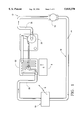
- FIG. 1 is a schematic of a thermally managed liquid cooling module incorporating features of the present invention
- FIG. 2 is a partial schematic of a thermally managed liquid cooling module incorporating features of the present invention
- FIG. 3 is a schematic view of a vortex sensor suitable for use in conjunction with the thermally managed liquid cooling module of FIGS. 1 and 2;
- FIG. 4 is a schematic view of a vortex amplifier suitable for use in conjunction with the thermally managed liquid cooling module of FIGS. 1 and 2;
- FIG. 5 is a graphical representation of the gain characteristics of the vortex amplifier of FIG. 6;
- FIG. 6 is a depiction of a laminated fluidic module incorporating features of the present invention.
- FIG. 7 is a top plan view of a laminated fluidic module incorporating features of the present invention.
- FIG. 8 is a side view of the laminated module of FIG. 7.
- FIG. 1 shows a liquid cooling module generally denoted by reference numeral 10 having a pump 12 which circulates a liquid coolant 14, through a closed loop passage 16.
- Coolant 14 may be FREON 22, ammonia, Monsanto coolant or other liquid coolant suitable for cooling electronics or other heat-producing components.
- the coolant 14 flows from pump 12 through a heat exchanger or other heat rejection means 18 into a distribution manifold 20, and thereafter into a cooling plate 22, which is in contact with, and conducts heat away from heat-producing electronic component 8.
- Coolant flowing through cooling plate 22 is regulated by flow regulator 26, which is in-line with the flow discharged from cooling plate 22. Coolant discharged from flow regulator 26 is collected in collection manifold 30 and returned to pump 12 to complete the closed-loop path.
- cooling plate 22 includes an inlet 34 in fluid communication with distribution manifold 20. Coolant flowing in inlet 34 is directed into a primary cooling passage 36 and a secondary cooling passage 38. The flow of coolant in primary cooling passage 36 follows a circuitous path through cooling plate 22 absorbing thermal energy from cooling plate 22 until the coolant is discharged at outlet 42. Similarly, liquid coolant flowing through secondary cooling passage 38 absorbs thermal energy from cooling plate 22 until is discharged through control port 40. The flow of liquid coolant discharged through outlet 42 enters primary inlet 50 of flow regulator 26 via duct 49. The flow of liquid coolant discharged through control port 40 similarly enters control port 52 of flow regulator 26 via duct 51.
- flow regulator 26 is preferably laminated directly onto cold plate 22 such that inlet 50 and control port 52 are immediately adjacent control port 40 and outlet 42. Accordingly, ducts 49 and 51 are shown schematically in FIG. 2 as tubular ducts for explanatory purposes only.
- the distribution manifold 20 is provided with an additional outlet in fluid communication with inlet 35 of an additional cooling plate 24.
- Flow of coolant 14 through cooling plate 24 is regulated by an additional flow regulator 28.
- a substantially equal pressure exists at inlet 34 and inlet 35, such that coolant 14 in manifold 20 flows in parallel paths either through cooling plate 22 or cooling plate 24.
- additional cooling plates with associated flow regulators are connected between distribution manifold 20 and collection manifold 30 to provide cooling for additional components.
- a bypass between distribution manifold 20 and collection manifold 30 needs to be provided.
- cooling liquid is constantly flowing through the cooling module 10 and through each of the cooling plates.
- the flow rate of the cooling liquid is selected, in a manner familiar to those skilled in the art, for the average thermal load of all the cooling plates in the cooling module 10. This operating condition is referred to as the design point.
- the flow through control port 40 is in the range of 5 to 25 percent of the flow through outlet 42, with 15 percent being preferred.
- a fluidic vortex orifice 46 Immediately upstream of control port 40 of cooling plate 22 is a fluidic vortex orifice 46. As shown in FIG. 3, as cooling fluid enters through tangential port 48, it flows in a generally circumferential, spiral path 49 and is discharged axially through control port 40 and into duct 51. As the flow rate increases, the circumferential component of the flow increases thereby generating an increasing radial pressure gradient. As the radial pressure gradient increases, resistance to flow through the control port 40 increases.
- flow regulator 26 comprises a fluidic vortex amplifier 29 having primary radial inlet port 50 and a tangential control port 52. Fluid entering primary inlet port 50 and control port 52 is discharged through regulator exhaust or output port 56.
- FIG. 5 is illustrative of the input-output characteristics of vortex amplifier 29.
- the control port pressure P c , the inlet port pressure P s , and output port pressure P o are selected so that the amplifier ratio (P c -P o )/(P s -P o ) is between 1.1 and 1.3.
- operation of a cooling module 10 is as follows.
- the flow through control port 40 is preferably 15 percent of the flow through outlet 42.
- An increase in thermal load causes one of the cooling plates, in this case cooling plate 22 to warm.
- the temperature of the liquid coolant 14 rises and its viscosity decreases.
- the vortex orifice 46 attenuates the flow through control port 40 so that the flow through control port 40 may now only be 10 percent of the flow through outlet 42.
- pressure is proportional to flow, the increase in P s is greater than the increase in PC so that the amplifier ratio decreases permitting increased flow through input port 50.
- distribution manifold 20 may be sized in order to have an insignificant pressure drop, such that the pressure at inlet 34 of cooling plate 22 is substantially equal to the pressure at inlet 35 of cooling plate 24, or the inlets of any other cooling plates in the system (not shown). This permits the rate of flow of coolant through cooling plate 22 to be regulated substantially exclusively by flow regulator 26.
- flow regulator 26 is laminated directly to cooling plate 22 to form a self-regulating cooling plate module.
- cooling plate 22, flow regulator 26, distribution manifold 20, collection manifold 30 and other components of the fluidic circuit are preferably constant cross-section features, which permit machining each component from thin sheets of stainless steel, titanium, inconel, or refractory metal having good thermal conductivity.
- These individual metal laminates 62, 64, 66, 68, 70 and 72 each contain two dimensional features which, when stacked together define the desired flow path. Individual layers in the laminated module communicate through feed through holes 74 strategically located in each laminate.
- the individual metal laminates 62-72 are preferably plated or diffusion coated, then furnace bonded to form a solid hermetic laminated stack, which may then be placed against, bonded to, or otherwise oriented adjacent electronic component 8 (not shown) or other component be cooled.
- the machining operations are conducted using electron discharge machining (EDM) or conventional photolithography techniques common in the electronics industry.
- EDM electron discharge machining
- distribution manifold 20 and collection manifold 30 each comprise a laminate in a relatively larger cross-section module 76, having relatively smaller laminated cooling modules 90, 92, 94, 96, 98, and 100.
- Feed-through holes 74 permit manifolds 20 and 30 to communicate with inlet 34 and outlet 51, inlet 34' and outlet 51' inlet 34'" and outlet 51'” and each successive inlet and outlet of each cooling plate module, to enable each cooling plate module 90-100 to independently regulate coolant flow therethrough.
- each laminated stack comprising a cooling plate 22 may be individually adjusted for thickness to enable a single large module 76 to simultaneously cool multiple components of varying heights.
Landscapes
- Engineering & Computer Science (AREA)
- Microelectronics & Electronic Packaging (AREA)
- Physics & Mathematics (AREA)
- Thermal Sciences (AREA)
- Cooling Or The Like Of Electrical Apparatus (AREA)
Abstract
Description
Claims (10)
Priority Applications (1)
| Application Number | Priority Date | Filing Date | Title |
|---|---|---|---|
| US08/857,260 US5815370A (en) | 1997-05-16 | 1997-05-16 | Fluidic feedback-controlled liquid cooling module |
Applications Claiming Priority (1)
| Application Number | Priority Date | Filing Date | Title |
|---|---|---|---|
| US08/857,260 US5815370A (en) | 1997-05-16 | 1997-05-16 | Fluidic feedback-controlled liquid cooling module |
Publications (1)
| Publication Number | Publication Date |
|---|---|
| US5815370A true US5815370A (en) | 1998-09-29 |
Family
ID=25325580
Family Applications (1)
| Application Number | Title | Priority Date | Filing Date |
|---|---|---|---|
| US08/857,260 Expired - Fee Related US5815370A (en) | 1997-05-16 | 1997-05-16 | Fluidic feedback-controlled liquid cooling module |
Country Status (1)
| Country | Link |
|---|---|
| US (1) | US5815370A (en) |
Cited By (42)
| Publication number | Priority date | Publication date | Assignee | Title |
|---|---|---|---|---|
| US6161612A (en) * | 1998-06-02 | 2000-12-19 | Ericsson Inc. | Cooling system and method for distributing cooled air |
| US6307746B1 (en) | 1999-12-06 | 2001-10-23 | Gateway, Inc. | Power adapter having a thermal cooling assembly for a digital information appliance |
| US6404631B1 (en) * | 2000-11-08 | 2002-06-11 | Hyundai Electronics Industries, Co., Ltd. | Cooling device of linear power amplifier in mobile communication system |
| US6568203B1 (en) * | 2002-05-01 | 2003-05-27 | Honeywell International, Inc. | Aircraft ground support air conditioning unit with cooling turbine bypass |
| US6697253B2 (en) * | 2000-12-20 | 2004-02-24 | Hitachi, Ltd. | Liquid cooling system and personal computer using thereof |
| US6746790B2 (en) | 2001-08-15 | 2004-06-08 | Metallic Power, Inc. | Power system including heat removal unit for providing backup power to one or more loads |
| US20040250563A1 (en) * | 2003-06-10 | 2004-12-16 | Masao Nakano | Semiconductor cooling device |
| US20050126752A1 (en) * | 2003-12-02 | 2005-06-16 | Hitoshi Matsushima | Electronic apparatus |
| WO2005109613A1 (en) * | 2004-05-11 | 2005-11-17 | Negenco Aps | An electromagnetic pump and use thereof |
| US20050262861A1 (en) * | 2004-05-25 | 2005-12-01 | Weber Richard M | Method and apparatus for controlling cooling with coolant at a subambient pressure |
| US20060118292A1 (en) * | 2002-07-11 | 2006-06-08 | Raytheon Company, A Delaware Corporation | Method and apparatus for cooling with coolant at a subambient pressure |
| US20060144619A1 (en) * | 2005-01-06 | 2006-07-06 | Halliburton Energy Services, Inc. | Thermal management apparatus, systems, and methods |
| US20060179861A1 (en) * | 2005-02-15 | 2006-08-17 | Weber Richard M | Method and apparatus for cooling with coolant at a subambient pressure |
| US20070119572A1 (en) * | 2005-11-30 | 2007-05-31 | Raytheon Company | System and Method for Boiling Heat Transfer Using Self-Induced Coolant Transport and Impingements |
| US20070119568A1 (en) * | 2005-11-30 | 2007-05-31 | Raytheon Company | System and method of enhanced boiling heat transfer using pin fins |
| US20070139889A1 (en) * | 2005-12-21 | 2007-06-21 | Sun Microsystems, Inc. | Feedback controlled magneto-hydrodynamic heat sink |
| US20070209782A1 (en) * | 2006-03-08 | 2007-09-13 | Raytheon Company | System and method for cooling a server-based data center with sub-ambient cooling |
| US20070263356A1 (en) * | 2006-05-02 | 2007-11-15 | Raytheon Company | Method and Apparatus for Cooling Electronics with a Coolant at a Subambient Pressure |
| US20080196867A1 (en) * | 2007-02-19 | 2008-08-21 | Liebert Corporation | Cooling Fluid Flow Regulation Distribution System and Method |
| US20090211277A1 (en) * | 2008-02-25 | 2009-08-27 | Raytheon Company | System and method for cooling a heat generating structure |
| US20090244830A1 (en) * | 2008-03-25 | 2009-10-01 | Raytheon Company | Systems and Methods for Cooling a Computing Component in a Computing Rack |
| US20100242492A1 (en) * | 2009-03-30 | 2010-09-30 | Honeywell International Inc. | Distributed engine control systems and gas turbine engines |
| FR2949038A1 (en) * | 2009-07-16 | 2011-02-11 | Hamilton Sundstrand Corp | Motor controller system useful in a controller and cooling system of an aircraft, comprises motor controllers, a coolant system having common inlet and outlet lines, and a control for selectively increasing a flow of coolant |
| US20110057539A1 (en) * | 2007-03-28 | 2011-03-10 | Gunnar Russberg | Generator device and method |
| US7921655B2 (en) | 2007-09-21 | 2011-04-12 | Raytheon Company | Topping cycle for a sub-ambient cooling system |
| US20110186300A1 (en) * | 2009-08-18 | 2011-08-04 | Dykstra Jason D | Method and apparatus for autonomous downhole fluid selection with pathway dependent resistance system |
| CN102268978A (en) * | 2010-06-02 | 2011-12-07 | 哈利伯顿能源服务公司 | Variable flow resistance system for use in subterranean well |
| US8616290B2 (en) | 2010-04-29 | 2013-12-31 | Halliburton Energy Services, Inc. | Method and apparatus for controlling fluid flow using movable flow diverter assembly |
| US8651172B2 (en) | 2007-03-22 | 2014-02-18 | Raytheon Company | System and method for separating components of a fluid coolant for cooling a structure |
| US20140268561A1 (en) * | 2013-03-18 | 2014-09-18 | Fujitsu Limited | Electronic equipment and heat receiving device |
| US8991506B2 (en) | 2011-10-31 | 2015-03-31 | Halliburton Energy Services, Inc. | Autonomous fluid control device having a movable valve plate for downhole fluid selection |
| US9127526B2 (en) | 2012-12-03 | 2015-09-08 | Halliburton Energy Services, Inc. | Fast pressure protection system and method |
| US9260952B2 (en) | 2009-08-18 | 2016-02-16 | Halliburton Energy Services, Inc. | Method and apparatus for controlling fluid flow in an autonomous valve using a sticky switch |
| US9291032B2 (en) | 2011-10-31 | 2016-03-22 | Halliburton Energy Services, Inc. | Autonomous fluid control device having a reciprocating valve for downhole fluid selection |
| US20160183407A1 (en) * | 2014-12-19 | 2016-06-23 | Fujitsu Limited | Board assembly including cooling system and electronic apparatus |
| US20160205807A1 (en) * | 2015-01-09 | 2016-07-14 | Msi Computer (Shenzhen) Co., Ltd. | Liquid Cooling Apparatus |
| US9404349B2 (en) | 2012-10-22 | 2016-08-02 | Halliburton Energy Services, Inc. | Autonomous fluid control system having a fluid diode |
| US9695654B2 (en) | 2012-12-03 | 2017-07-04 | Halliburton Energy Services, Inc. | Wellhead flowback control system and method |
| US20190302859A1 (en) * | 2018-04-02 | 2019-10-03 | Lenovo (Beijing) Co., Ltd. | Water-cooled server and electronic device |
| CN111710933A (en) * | 2019-03-18 | 2020-09-25 | 上汽通用汽车有限公司 | Battery pack and vehicle with same |
| EP3875376A1 (en) * | 2020-03-03 | 2021-09-08 | The Boeing Company | Space vehicle comprising cooling system |
| US20220078942A1 (en) * | 2020-09-10 | 2022-03-10 | Scott Douglas Bennett | Systems and methods for optimizing flow rates in immersion cooling |
Citations (5)
| Publication number | Priority date | Publication date | Assignee | Title |
|---|---|---|---|---|
| US3999105A (en) * | 1974-04-19 | 1976-12-21 | International Business Machines Corporation | Liquid encapsulated integrated circuit package |
| US5050037A (en) * | 1984-01-26 | 1991-09-17 | Fujitsu Limited | Liquid-cooling module system for electronic circuit components |
| US5190099A (en) * | 1991-05-01 | 1993-03-02 | The United States Of The America As Represented By The Secretary Of The Army | Pulsatile impinging cooling system for electronic IC modules and systems using fluidic oscillators |
| US5469331A (en) * | 1994-04-07 | 1995-11-21 | Conway; Harry E. | Cooling system for modular power supply device |
| US5550436A (en) * | 1994-09-01 | 1996-08-27 | International Rectifier Corporation | MOS gate driver integrated circuit for ballast circuits |
-
1997
- 1997-05-16 US US08/857,260 patent/US5815370A/en not_active Expired - Fee Related
Patent Citations (5)
| Publication number | Priority date | Publication date | Assignee | Title |
|---|---|---|---|---|
| US3999105A (en) * | 1974-04-19 | 1976-12-21 | International Business Machines Corporation | Liquid encapsulated integrated circuit package |
| US5050037A (en) * | 1984-01-26 | 1991-09-17 | Fujitsu Limited | Liquid-cooling module system for electronic circuit components |
| US5190099A (en) * | 1991-05-01 | 1993-03-02 | The United States Of The America As Represented By The Secretary Of The Army | Pulsatile impinging cooling system for electronic IC modules and systems using fluidic oscillators |
| US5469331A (en) * | 1994-04-07 | 1995-11-21 | Conway; Harry E. | Cooling system for modular power supply device |
| US5550436A (en) * | 1994-09-01 | 1996-08-27 | International Rectifier Corporation | MOS gate driver integrated circuit for ballast circuits |
Non-Patent Citations (2)
| Title |
|---|
| AiResearch Final Report 76 411546 dated Oct. 19, 1976, Program to Design, Fabricate, Test, and Deliver a Thermal Control Mixing Control Device for George C. Marshall Space Flight Center National Aeronautics & Space Administration (Contract No. NAS3 31289) . * |
| AiResearch Final Report 76-411546 dated Oct. 19, 1976, "Program to Design, Fabricate, Test, and Deliver a Thermal Control-Mixing Control Device for George C. Marshall Space Flight Center National Aeronautics & Space Administration (Contract No. NAS3-31289)". |
Cited By (81)
| Publication number | Priority date | Publication date | Assignee | Title |
|---|---|---|---|---|
| US6161612A (en) * | 1998-06-02 | 2000-12-19 | Ericsson Inc. | Cooling system and method for distributing cooled air |
| US6307746B1 (en) | 1999-12-06 | 2001-10-23 | Gateway, Inc. | Power adapter having a thermal cooling assembly for a digital information appliance |
| US6404631B1 (en) * | 2000-11-08 | 2002-06-11 | Hyundai Electronics Industries, Co., Ltd. | Cooling device of linear power amplifier in mobile communication system |
| US6873525B2 (en) | 2000-12-20 | 2005-03-29 | Hitachi, Ltd. | Liquid cooling system and personal computer using the same |
| US6972954B2 (en) | 2000-12-20 | 2005-12-06 | Hitachi, Ltd. | Liquid cooling system and personal computer using the same |
| US20040228088A1 (en) * | 2000-12-20 | 2004-11-18 | Rintaro Minamitani | Liquid cooling system and personal computer using the same |
| US6697253B2 (en) * | 2000-12-20 | 2004-02-24 | Hitachi, Ltd. | Liquid cooling system and personal computer using thereof |
| US6746790B2 (en) | 2001-08-15 | 2004-06-08 | Metallic Power, Inc. | Power system including heat removal unit for providing backup power to one or more loads |
| US6568203B1 (en) * | 2002-05-01 | 2003-05-27 | Honeywell International, Inc. | Aircraft ground support air conditioning unit with cooling turbine bypass |
| US7607475B2 (en) | 2002-07-11 | 2009-10-27 | Raytheon Company | Apparatus for cooling with coolant at subambient pressure |
| US20060118292A1 (en) * | 2002-07-11 | 2006-06-08 | Raytheon Company, A Delaware Corporation | Method and apparatus for cooling with coolant at a subambient pressure |
| US20040250563A1 (en) * | 2003-06-10 | 2004-12-16 | Masao Nakano | Semiconductor cooling device |
| US7044198B2 (en) * | 2003-12-02 | 2006-05-16 | Hitachi, Ltd. | Electronic apparatus |
| US20050126752A1 (en) * | 2003-12-02 | 2005-06-16 | Hitoshi Matsushima | Electronic apparatus |
| WO2005109613A1 (en) * | 2004-05-11 | 2005-11-17 | Negenco Aps | An electromagnetic pump and use thereof |
| US20050262861A1 (en) * | 2004-05-25 | 2005-12-01 | Weber Richard M | Method and apparatus for controlling cooling with coolant at a subambient pressure |
| US20060144619A1 (en) * | 2005-01-06 | 2006-07-06 | Halliburton Energy Services, Inc. | Thermal management apparatus, systems, and methods |
| WO2006074393A1 (en) * | 2005-01-06 | 2006-07-13 | Halliburton Energy Services, Inc. | Thermal management apparatus, systems, and methods |
| US7254957B2 (en) | 2005-02-15 | 2007-08-14 | Raytheon Company | Method and apparatus for cooling with coolant at a subambient pressure |
| US20060179861A1 (en) * | 2005-02-15 | 2006-08-17 | Weber Richard M | Method and apparatus for cooling with coolant at a subambient pressure |
| US20070119568A1 (en) * | 2005-11-30 | 2007-05-31 | Raytheon Company | System and method of enhanced boiling heat transfer using pin fins |
| US20090020266A1 (en) * | 2005-11-30 | 2009-01-22 | Raytheon Company | System and Method of Boiling Heat Transfer Using Self-Induced Coolant Transport and Impingements |
| US9383145B2 (en) | 2005-11-30 | 2016-07-05 | Raytheon Company | System and method of boiling heat transfer using self-induced coolant transport and impingements |
| US20070119572A1 (en) * | 2005-11-30 | 2007-05-31 | Raytheon Company | System and Method for Boiling Heat Transfer Using Self-Induced Coolant Transport and Impingements |
| US20070139889A1 (en) * | 2005-12-21 | 2007-06-21 | Sun Microsystems, Inc. | Feedback controlled magneto-hydrodynamic heat sink |
| US7245495B2 (en) * | 2005-12-21 | 2007-07-17 | Sun Microsystems, Inc. | Feedback controlled magneto-hydrodynamic heat sink |
| US20070209782A1 (en) * | 2006-03-08 | 2007-09-13 | Raytheon Company | System and method for cooling a server-based data center with sub-ambient cooling |
| US7908874B2 (en) | 2006-05-02 | 2011-03-22 | Raytheon Company | Method and apparatus for cooling electronics with a coolant at a subambient pressure |
| US8490418B2 (en) | 2006-05-02 | 2013-07-23 | Raytheon Company | Method and apparatus for cooling electronics with a coolant at a subambient pressure |
| US20070263356A1 (en) * | 2006-05-02 | 2007-11-15 | Raytheon Company | Method and Apparatus for Cooling Electronics with a Coolant at a Subambient Pressure |
| US20080196867A1 (en) * | 2007-02-19 | 2008-08-21 | Liebert Corporation | Cooling Fluid Flow Regulation Distribution System and Method |
| US8833097B2 (en) * | 2007-02-19 | 2014-09-16 | Liebert Corporation | Cooling fluid flow regulation distribution system and method |
| US8011200B2 (en) * | 2007-02-19 | 2011-09-06 | Liebert Corporation | Cooling fluid flow regulation distribution system and method |
| US20110272125A1 (en) * | 2007-02-19 | 2011-11-10 | Liebert Corporation | Cooling Fluid Flow Regulation Distribution System and Method |
| US8651172B2 (en) | 2007-03-22 | 2014-02-18 | Raytheon Company | System and method for separating components of a fluid coolant for cooling a structure |
| US20110057539A1 (en) * | 2007-03-28 | 2011-03-10 | Gunnar Russberg | Generator device and method |
| US8129882B2 (en) * | 2007-03-28 | 2012-03-06 | Abb Research Ltd. | Thermoelectric generator and method of generating electricity |
| US7921655B2 (en) | 2007-09-21 | 2011-04-12 | Raytheon Company | Topping cycle for a sub-ambient cooling system |
| US7934386B2 (en) | 2008-02-25 | 2011-05-03 | Raytheon Company | System and method for cooling a heat generating structure |
| US20090211277A1 (en) * | 2008-02-25 | 2009-08-27 | Raytheon Company | System and method for cooling a heat generating structure |
| US20090244830A1 (en) * | 2008-03-25 | 2009-10-01 | Raytheon Company | Systems and Methods for Cooling a Computing Component in a Computing Rack |
| US7907409B2 (en) | 2008-03-25 | 2011-03-15 | Raytheon Company | Systems and methods for cooling a computing component in a computing rack |
| US20100242492A1 (en) * | 2009-03-30 | 2010-09-30 | Honeywell International Inc. | Distributed engine control systems and gas turbine engines |
| FR2949038A1 (en) * | 2009-07-16 | 2011-02-11 | Hamilton Sundstrand Corp | Motor controller system useful in a controller and cooling system of an aircraft, comprises motor controllers, a coolant system having common inlet and outlet lines, and a control for selectively increasing a flow of coolant |
| US20110308806A9 (en) * | 2009-08-18 | 2011-12-22 | Dykstra Jason D | Method and apparatus for autonomous downhole fluid selection with pathway dependent resistance system |
| US8931566B2 (en) | 2009-08-18 | 2015-01-13 | Halliburton Energy Services, Inc. | Method and apparatus for autonomous downhole fluid selection with pathway dependent resistance system |
| US20110186300A1 (en) * | 2009-08-18 | 2011-08-04 | Dykstra Jason D | Method and apparatus for autonomous downhole fluid selection with pathway dependent resistance system |
| US9260952B2 (en) | 2009-08-18 | 2016-02-16 | Halliburton Energy Services, Inc. | Method and apparatus for controlling fluid flow in an autonomous valve using a sticky switch |
| US8657017B2 (en) | 2009-08-18 | 2014-02-25 | Halliburton Energy Services, Inc. | Method and apparatus for autonomous downhole fluid selection with pathway dependent resistance system |
| US9109423B2 (en) * | 2009-08-18 | 2015-08-18 | Halliburton Energy Services, Inc. | Apparatus for autonomous downhole fluid selection with pathway dependent resistance system |
| US8714266B2 (en) | 2009-08-18 | 2014-05-06 | Halliburton Energy Services, Inc. | Method and apparatus for autonomous downhole fluid selection with pathway dependent resistance system |
| US9080410B2 (en) | 2009-08-18 | 2015-07-14 | Halliburton Energy Services, Inc. | Method and apparatus for autonomous downhole fluid selection with pathway dependent resistance system |
| CN102753784B (en) * | 2010-02-04 | 2016-03-16 | 哈利伯顿能源服务公司 | For selecting from main downhole fluid and there is the method and apparatus of path dependent form resistance system |
| US9133685B2 (en) | 2010-02-04 | 2015-09-15 | Halliburton Energy Services, Inc. | Method and apparatus for autonomous downhole fluid selection with pathway dependent resistance system |
| AU2016208452B2 (en) * | 2010-02-04 | 2017-05-25 | Halliburton Energy Services, Inc. | Method and apparatus for autonomous downhole fluid selection with pathway dependent resistance system |
| CN105604529B (en) * | 2010-02-04 | 2019-04-23 | 哈利伯顿能源服务公司 | Well device and flow control device, in the wellbore of underground autonomous directed stream method |
| CN105604529A (en) * | 2010-02-04 | 2016-05-25 | 哈利伯顿能源服务公司 | Well apparatus, flow control apparatus and method for autonomously guiding flow in borehole in well |
| AU2011213212B2 (en) * | 2010-02-04 | 2016-05-05 | Halliburton Energy Services, Inc. | Method and apparatus for autonomous downhole fluid selection with pathway dependent resistance system |
| CN102753784A (en) * | 2010-02-04 | 2012-10-24 | 哈利伯顿能源服务公司 | Method and apparatus for autonomous downhole fluid selection with pathway dependent resistance system |
| US8757266B2 (en) | 2010-04-29 | 2014-06-24 | Halliburton Energy Services, Inc. | Method and apparatus for controlling fluid flow using movable flow diverter assembly |
| US8708050B2 (en) | 2010-04-29 | 2014-04-29 | Halliburton Energy Services, Inc. | Method and apparatus for controlling fluid flow using movable flow diverter assembly |
| US8616290B2 (en) | 2010-04-29 | 2013-12-31 | Halliburton Energy Services, Inc. | Method and apparatus for controlling fluid flow using movable flow diverter assembly |
| US8622136B2 (en) | 2010-04-29 | 2014-01-07 | Halliburton Energy Services, Inc. | Method and apparatus for controlling fluid flow using movable flow diverter assembly |
| US8985222B2 (en) | 2010-04-29 | 2015-03-24 | Halliburton Energy Services, Inc. | Method and apparatus for controlling fluid flow using movable flow diverter assembly |
| CN102268978B (en) * | 2010-06-02 | 2016-02-10 | 哈利伯顿能源服务公司 | The variable flow resistance system used in missile silo |
| CN102268978A (en) * | 2010-06-02 | 2011-12-07 | 哈利伯顿能源服务公司 | Variable flow resistance system for use in subterranean well |
| US9291032B2 (en) | 2011-10-31 | 2016-03-22 | Halliburton Energy Services, Inc. | Autonomous fluid control device having a reciprocating valve for downhole fluid selection |
| US8991506B2 (en) | 2011-10-31 | 2015-03-31 | Halliburton Energy Services, Inc. | Autonomous fluid control device having a movable valve plate for downhole fluid selection |
| US9404349B2 (en) | 2012-10-22 | 2016-08-02 | Halliburton Energy Services, Inc. | Autonomous fluid control system having a fluid diode |
| US9127526B2 (en) | 2012-12-03 | 2015-09-08 | Halliburton Energy Services, Inc. | Fast pressure protection system and method |
| US9695654B2 (en) | 2012-12-03 | 2017-07-04 | Halliburton Energy Services, Inc. | Wellhead flowback control system and method |
| US20140268561A1 (en) * | 2013-03-18 | 2014-09-18 | Fujitsu Limited | Electronic equipment and heat receiving device |
| US20160183407A1 (en) * | 2014-12-19 | 2016-06-23 | Fujitsu Limited | Board assembly including cooling system and electronic apparatus |
| US9717161B2 (en) * | 2014-12-19 | 2017-07-25 | Fujitsu Limited | Board assembly including cooling system and electronic apparatus |
| US9839157B2 (en) * | 2015-01-09 | 2017-12-05 | Msi Computer (Shenzhen) Co., Ltd. | Liquid cooling apparatus |
| US20160205807A1 (en) * | 2015-01-09 | 2016-07-14 | Msi Computer (Shenzhen) Co., Ltd. | Liquid Cooling Apparatus |
| US20190302859A1 (en) * | 2018-04-02 | 2019-10-03 | Lenovo (Beijing) Co., Ltd. | Water-cooled server and electronic device |
| US10754397B2 (en) * | 2018-04-02 | 2020-08-25 | Lenovo (Beijing) Co., Ltd. | Water-cooled server and electronic device |
| CN111710933A (en) * | 2019-03-18 | 2020-09-25 | 上汽通用汽车有限公司 | Battery pack and vehicle with same |
| EP3875376A1 (en) * | 2020-03-03 | 2021-09-08 | The Boeing Company | Space vehicle comprising cooling system |
| US20220078942A1 (en) * | 2020-09-10 | 2022-03-10 | Scott Douglas Bennett | Systems and methods for optimizing flow rates in immersion cooling |
Similar Documents
| Publication | Publication Date | Title |
|---|---|---|
| US5815370A (en) | Fluidic feedback-controlled liquid cooling module | |
| US8797741B2 (en) | Maintaining thermal uniformity in micro-channel cold plates with two-phase flows | |
| US10890389B2 (en) | Heat exchanger assemblies with integrated valve | |
| US5088005A (en) | Cold plate for cooling electronics | |
| JP3231749B2 (en) | Electronic system and electronic module cooling method | |
| EP2147860B1 (en) | Heat exchanger assembly for an aircraft control | |
| JP6375109B2 (en) | Reusable thermal protection system with high thermal conductivity | |
| US8029248B2 (en) | Integrated coolant pumping module | |
| US10526971B2 (en) | Super-cooled heat exchanger of an air cycle machine | |
| US3440833A (en) | Vapor cycle refrigeration system | |
| WO2013109535A1 (en) | Parallel evaporator circuit with balanced flow | |
| US20120012299A1 (en) | Proportional Micro-Valve With Thermal Feedback | |
| US11796226B2 (en) | System for supporting intermittent fast transient heat loads | |
| US20120097370A1 (en) | flow balancing scheme for two-phase refrigerant cooled rack | |
| US5289869A (en) | Closed loop feedback control variable conductance heat pipe | |
| US11428479B2 (en) | Compact thermal control plate | |
| US5329996A (en) | Porous layer heat exchanger | |
| CN218918064U (en) | Rack-mounted server and heat dissipation system thereof | |
| US20210396477A1 (en) | Architecture and Operational Modes of Pump-Augmented Loop Heat Pipe with Multiple Evaporators | |
| EP4305937A1 (en) | Cold plate with integrated sliding pedestal and processing system including the same | |
| KR20230020988A (en) | Vacuum system apparatus and method | |
| JP2753159B2 (en) | Cold plate and cooling device using the same | |
| US20240088475A1 (en) | High efficiency cold plate | |
| Leimkuehler et al. | Development of a contaminant insensitive sublimator | |
| US20240088474A1 (en) | High efficiency cold plate |
Legal Events
| Date | Code | Title | Description |
|---|---|---|---|
| AS | Assignment |
Owner name: ALLIEDSIGNAL INC., NEW JERSEY Free format text: ASSIGNMENT OF ASSIGNORS INTEREST;ASSIGNOR:SUTTON, TREVOR G.;REEL/FRAME:008566/0366 Effective date: 19970515 |
|
| CC | Certificate of correction | ||
| FEPP | Fee payment procedure |
Free format text: PAYOR NUMBER ASSIGNED (ORIGINAL EVENT CODE: ASPN); ENTITY STATUS OF PATENT OWNER: LARGE ENTITY |
|
| FPAY | Fee payment |
Year of fee payment: 4 |
|
| FPAY | Fee payment |
Year of fee payment: 8 |
|
| REMI | Maintenance fee reminder mailed | ||
| LAPS | Lapse for failure to pay maintenance fees | ||
| STCH | Information on status: patent discontinuation |
Free format text: PATENT EXPIRED DUE TO NONPAYMENT OF MAINTENANCE FEES UNDER 37 CFR 1.362 |
|
| FP | Lapsed due to failure to pay maintenance fee |
Effective date: 20100929 |