EP1538618A2 - Méthode de détermination du type de disque dans un appareil de disque optique - Google Patents
Méthode de détermination du type de disque dans un appareil de disque optique Download PDFInfo
- Publication number
- EP1538618A2 EP1538618A2 EP04292688A EP04292688A EP1538618A2 EP 1538618 A2 EP1538618 A2 EP 1538618A2 EP 04292688 A EP04292688 A EP 04292688A EP 04292688 A EP04292688 A EP 04292688A EP 1538618 A2 EP1538618 A2 EP 1538618A2
- Authority
- EP
- European Patent Office
- Prior art keywords
- disc
- disc type
- optical disc
- type
- optical
- Prior art date
- Legal status (The legal status is an assumption and is not a legal conclusion. Google has not performed a legal analysis and makes no representation as to the accuracy of the status listed.)
- Withdrawn
Links
Images



Classifications
-
- G—PHYSICS
- G11—INFORMATION STORAGE
- G11B—INFORMATION STORAGE BASED ON RELATIVE MOVEMENT BETWEEN RECORD CARRIER AND TRANSDUCER
- G11B19/00—Driving, starting, stopping record carriers not specifically of filamentary or web form, or of supports therefor; Control thereof; Control of operating function ; Driving both disc and head
- G11B19/02—Control of operating function, e.g. switching from recording to reproducing
- G11B19/12—Control of operating function, e.g. switching from recording to reproducing by sensing distinguishing features of or on records, e.g. diameter end mark
-
- G—PHYSICS
- G11—INFORMATION STORAGE
- G11B—INFORMATION STORAGE BASED ON RELATIVE MOVEMENT BETWEEN RECORD CARRIER AND TRANSDUCER
- G11B7/00—Recording or reproducing by optical means, e.g. recording using a thermal beam of optical radiation by modifying optical properties or the physical structure, reproducing using an optical beam at lower power by sensing optical properties; Record carriers therefor
- G11B7/002—Recording, reproducing or erasing systems characterised by the shape or form of the carrier
- G11B7/0037—Recording, reproducing or erasing systems characterised by the shape or form of the carrier with discs
Definitions
- the present invention relates to a method for determining disc type in an optical disc device, and more particularly to a method for efficiently determining the type of an optical disc inserted into a multi-disc device capable of reproducing and/or recording data in a manner suitable for various optical discs such as CDs or DVDs.
- optical discs capable of recording or storing high quality, long duration audio and video data are in widespread use.
- An optical disc device such as a multi-disc recorder capable of reproducing or recording data on the various types of optical discs has been commercialized.
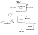
- the optical disc device such as the multi-disc recorder includes an optical pickup 11 for accessing an optical disc 10, a play & record system 12, a microcomputer 13, and a memory 14.
- the microcomputer 13 performs a series of operations for determining the type of the optical disc 10 inserted into the optical disc device.
- the microcomputer 13 determines the type of the optical disc inserted into the optical disc device, for example, it determines whether the type of the optical disc 10 inserted in the device is CD-ROM, CD-R or CD-RW in the CD family, or DVD-ROM, DVD-R, DVD+R, DVD-RW, DVD+RW or DVD-RAM in the DVD family, and then performs a series of disc initialization operations, such as a servo operation and an information read operation, suitable for the determined disc type.
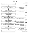
- Fig. 2 is a flow chart illustrating a disc type determination procedure according to a related art. If the disc type determination procedure is started, for example, with a DVD-R loaded in the optical disc device as shown in Fig. 2, the microcomputer 13 performs a first disc type determination operation in which it detects the level of a Focus Error (FE) signal and Radio Frequency (RF) signal to determine whether the loaded disc belongs to the CD or DVD family. If the detected level is high, the microcomputer 13 determines that the loaded disc belongs to the CD family. If the detected level is low, the microcomputer 13 determines that the loaded disc belongs to the DVD family. In this example, the microcomputer determines that the loaded disc belongs to the DVD family.
- FE Focus Error
- RF Radio Frequency
- the microcomputer 13 With the loaded disc determined to belong to the DVD family, the microcomputer 13 performs a second disc type determination operation in which it detects the level of DPP, FE and RF signals to determine whether the loaded disc belongs to the DVD-ROM, DVD-R or DVD-RW family. After the second disc type determination operation, the microcomputer 13 checks a rotation state of a spindle motor in the optical disc device to determine the size of the loaded disc ("8cm” from among two possible disc sizes of "8cm” and "12cm” in this example), and then controls focus and tracking servos.
- the microcomputer 13 While the focus and tracking servos are activated, the microcomputer 13 performs a third disc type determination operation in which it determines, based on the disc wobble form, whether the loaded disc belongs to the DVD-R, DVD+R, DVD-RW, or DVD+RW family. After the third disc type determination operation, the microcomputer 13 performs adjustment operations according to the disc characteristics such as disc eccentricity, unbalance, tilt and the like, and performs a disc information read operation.
- the microcomputer 13 reads disc information such as TOC (Table of Contents) information, ATIP (Absolute Time in Pregroove) information and the like, and if the loaded disc type is DVD, the microcomputer 13 reads disc information such as RMD, (Record Management Data), ADIP and LPP information, and control data.
- disc information such as TOC (Table of Contents) information, ATIP (Absolute Time in Pregroove) information and the like
- the microcomputer 13 reads disc information such as RMD, (Record Management Data), ADIP and LPP information, and control data.
- the general optical disc device In the general optical disc device, however, it takes a long time (for example, a total of 15.1 seconds for DVD-R) to determine the type of an optical disc inserted into the device since it must sequentially perform a number of the disc type determination operations as described above. Thus, a user must wait a long time until an operation or function desired by the user can actually start.
- a long time for example, a total of 15.1 seconds for DVD-R
- the present invention has been made in view of the above and other problems, and it is an object of the present invention to provide a method for efficiently and quickly determining the type of an optical disc inserted into a multi-disc device capable of reproducing or recording data on various types of optical discs.
- the above and other objects can be accomplished by the provision of a method for determining disc type in an optical disc device, in which the device performs a disc initialization procedure for a disc loaded into the device, assuming that the loaded disc type is a preset disc type, and checks whether or not the initialization procedure fails, and then performs a disc type determination procedure to determine the loaded disc type if the initialization procedure fails.
- the optical disc device cumulatively stores the initialized disc type or the determined disc type, and updates the preset disc type based on the cumulative frequency distribution of the stored disc types.
- a user may also select the disc type of the loaded disc by manipulating a switch provided on the optical disc device.
- Fig. 1 is a block diagram illustrating the configuration of a general optical disc device
- Fig. 2 is a flow chart illustrating a disc type determination procedure in a general optical disc device according to a related art
- Fig. 3 is a flow chart illustrating a disc type determination method in an optical disc device according to an embodiment of the present invention
- Fig. 4 illustrates examples of first and second knob switches provided on an optical disc device according to an embodiment of the present invention
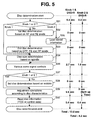
- Fig. 5 is a flow chart illustrating a method for determining disc type using the first or second knob switch according to an embodiment of the present invention.
- Fig. 6 is a flow chart illustrating how disc type information is stored in association with each switch number provided on the second knob switch according to an embodiment of the present invention.
- the disc type determination method according to the present invention can be applied to an optical disc device, such as a multi-disc recorder, configured as described above with reference to Fig. 1, or to other suitable devices and systems.
- an optical disc device such as a multi-disc recorder, configured as described above with reference to Fig. 1, or to other suitable devices and systems.
- Fig. 3 is a flow chart illustrating a disc type determination method in an optical disc device according to the present invention.
- the microcomputer 13 performs a series of disc type determination operations and an initialization procedure as known, e.g., as shown in Fig. 2 (S10), and cumulatively stores the determined disc types as disc type determination results in the memory 14, and calculates a cumulative frequency distribution of the determined disc types stored in the memory 14 (S11).
- the microcomputer 13 then performs an operation desired by a user such as disc playback or recording (S12).
- the microcomputer 13 checks the cumulative frequency distribution of the determined disc types as stored in the memory 14, and assumes that the type of the new optical disc is the most frequent disc type in the cumulative frequency distribution (S14). That is, the microcomputer 13 identifies the most frequently inserted disc by examining the stored cumulative frequency distribution and assumes that the currently inserted disc is of that type.
- the microcomputer 13 then performs a disc initialization procedure with a focus and tracking servo operation corresponding to the assumed disc type (S15). If the disc initialization procedure is not normally performed (i.e., it is not successfully performed) (S16), the microcomputer 13 performs a series of disc type determination operations as described above with reference to Fig. 2 to actually determine the type of the newly inserted optical disc, and performs a disc initialization procedure corresponding to the determined disc type (S17). On the other hand, if the disc initialization procedure is normally performed (i.e., it is successful) with the focus and tracking servo operation corresponding to the assumed disc type (S17), the microcomputer 13 omits the series of disc type determination operations of step S17 and proceeds to step S18.
- the disc type of the newly inserted disc (as correctly identified based on the assumption or actual determination) is cumulatively stored in the memory, thereby updating the cumulative frequency distribution of the disc types stored in the memory (S18).
- the microcomputer 13 then performs a function and/or operation desired by the user (S19).
- This disc type determination method of Fig. 3 reduces the time required to determine the disc type, thereby efficiently reducing the time the user must wait until an operation or function desired by the user is activated.
- a first (SW1) or second (SW2) knob switch is provided as shown in Fig. 4, which enables the user to specify the type of disc when they insert the disc into the optical disc device.
- the first or second knob switch can be provided on the optical disc device such as the device in Fig. 1, and is operatively coupled to the internal components (e.g., the Microm 13) of the optical disc device to implement the disc type determining methods of the invention as described below.
- the knob can be operated to make a selection among selectable items.
- the first knob switch SW1 can have a selection of DVD-ROM, DVD-R, DVD+R, DVD-RW, DVD+RW, DVD-RAM, CD-ROM, CD-R, or CD-RW.
- the second knob switch SW2 can have a selection of switch numbers 1, 2, 3, 4 or 5. These are examples only and the present invention encompasses other examples and other variations. Further, although knobs are shown in Fig. 4, other types of switches or selecting mechanisms can be used. The use of the first or second knob switch efficiently reduces the time required to determine the disc type.
- Fig. 5 is a flow chart illustrating a method for determining disc type using the first or second knob switch (e.g. SW1 or SW2 of Fig. 4) according to the present invention.
- the method of Fig. 5 can be implemented by the optical disc device of Fig. 1 or other suitable device/system.
- the microcomputer 13 omits the first and second disc type determination operations in the conventional disc type determination procedure shown in Fig. 2, and checks the rotation state of the spindle motor, determines whether the disc size is 12cm or 8cm, and controls the focus and tracking servo operations accordingly (S34 and S36).
- the method performs the first and second disc type determination operations in the conventional disc type determination procedure as shown in Fig. 2 (S32 and S33) and proceeds to step S34.
- the microcomputer 13 omits the first and second disc type determination operations and the disc size determination operation in the conventional disc type determination procedure shown in Fig. 2, and loads or reads information (for example, disc type information) stored in association with a selected switch number of the second knob switch and directly controls the focus and tracking servo operations accordingly (S35 and S36).
- the microcomputer 13 If the user specifies the disc type using the first or second knob switch (S37), the microcomputer 13 also omits the third disc type determination operation in the conventional disc type determination procedure shown in Fig. 2, and performs adjustment operations according to disc characteristics such as disc eccentricity, unbalance, tilt and the like (S39), and then performs a disc information read operation (S40). If no first or second knob switch is used or selected at step S37, the method performs the third disc type determination operation in the conventional disc type determination procedure as shown in Fig. 2 (S38) and proceeds to step S39.
- the use of the first or second knob switch to specify the disc type allows the disc type determination procedure to be terminated more quickly than the conventional disc type determination method. For example, for a DVD-R optical disc, it takes 15.1 seconds to determine the disc type according to the conventional method, whereas it takes, e.g., about 13.0 seconds when using the first knob switch and about 4.2 seconds when using the second knob switch according to the present invention.
- the microcomputer 13 checks whether or not the disc initialization procedure is normally performed. If the disc initialization procedure is not normally performed, the microcomputer 13 again performs a series of disc type determination operations as described above with reference to Fig. 2 to actually determine the type of the inserted disc, and performs a disc initialization procedure corresponding to the determined disc type.
- Fig. 6 is a flow chart illustrating how disc type information is stored in association with each switch number provided on the second knob switch (e.g., SW2 in Fig. 4) according to an embodiment of the present invention.
- the method of Fig. 6 can be implemented in the optical disc device of Fig. 1 or other suitable device/system.
- the user adjusts the second knob switch to a number "1".
- the user inserts an optical disc into the optical disc device having the second knob switch set to the number "1".
- the microcomputer 13 sets a flag indicating disc type information storage to "1" (S51).
- the microcomputer 13 then performs a series of disc type determination operations (S52), and performs a disc information read operation according to the determination results (S53).
- the microcomputer 13 checks whether or not the disc type information storage flag is set to "1" (S54). If the flag is set to "1", the microcomputer stores the information of the disc type determined in the disc type determination procedure at step S52 as described above, in association with the set switch number "1", in a memory, for example, a nonvolatile memory such as an EEPROM in the optical disc device (S55). In this manner, information of different disc types can be stored in association with the first to fifth numbers "1" to "5" provided on the second knob switch and subsequently used to more quickly access a newly inserted disc type as the user selects a switch number from the numbers 1-5 of the second knob switch.
- a memory for example, a nonvolatile memory such as an EEPROM in the optical disc device
- the present invention provides a method for determining disc type in an optical disc device, which allows the type of an optical disc inserted in the device to be determined more quickly and efficiently, thereby efficiently reducing waiting time so that an operation or function desired by the user can be more quickly activated.
Landscapes
- Optical Recording Or Reproduction (AREA)
Applications Claiming Priority (2)
| Application Number | Priority Date | Filing Date | Title |
|---|---|---|---|
| KR2003079524 | 2003-11-11 | ||
| KR1020030079524A KR100568374B1 (ko) | 2003-11-11 | 2003-11-11 | 광디스크 장치에서의 디스크 유형 판별방법 |
Publications (2)
| Publication Number | Publication Date |
|---|---|
| EP1538618A2 true EP1538618A2 (fr) | 2005-06-08 |
| EP1538618A3 EP1538618A3 (fr) | 2006-10-11 |
Family
ID=34464732
Family Applications (1)
| Application Number | Title | Priority Date | Filing Date |
|---|---|---|---|
| EP04292688A Withdrawn EP1538618A3 (fr) | 2003-11-11 | 2004-11-12 | Méthode de détermination du type de disque dans un appareil de disque optique |
Country Status (5)
| Country | Link |
|---|---|
| US (1) | US7602688B2 (fr) |
| EP (1) | EP1538618A3 (fr) |
| KR (1) | KR100568374B1 (fr) |
| CN (1) | CN1617247A (fr) |
| TW (1) | TWI349932B (fr) |
Cited By (1)
| Publication number | Priority date | Publication date | Assignee | Title |
|---|---|---|---|---|
| EP1667142A3 (fr) * | 2004-11-29 | 2007-06-13 | ORION ELECTRIC CO., Ltd. | Appareil de lecture de disques |
Families Citing this family (8)
| Publication number | Priority date | Publication date | Assignee | Title |
|---|---|---|---|---|
| KR100694113B1 (ko) * | 2005-05-24 | 2007-03-12 | 삼성전자주식회사 | 광 매체 종류 판별 방법 및 그에 적합한 광 매체 시스템과기록 매체 |
| US7971101B2 (en) * | 2006-02-02 | 2011-06-28 | Dell Products L.P. | Systems and methods for management and capturing of optical drive failure errors |
| WO2008047413A1 (fr) * | 2006-10-17 | 2008-04-24 | Pioneer Corporation | Dispositif de reproduction d'information |
| JP2009059406A (ja) * | 2007-08-30 | 2009-03-19 | Hitachi-Lg Data Storage Inc | 光ディスク装置及びパラメータ選択方法 |
| WO2014107608A1 (fr) | 2013-01-04 | 2014-07-10 | Carbo Ceramics Inc. | Agent de soutènement électroconducteur et procédés de détection, localisation et caractérisation de l'agent de soutènement électroconducteur |
| US11008505B2 (en) | 2013-01-04 | 2021-05-18 | Carbo Ceramics Inc. | Electrically conductive proppant |
| US9434875B1 (en) | 2014-12-16 | 2016-09-06 | Carbo Ceramics Inc. | Electrically-conductive proppant and methods for making and using same |
| US9551210B2 (en) | 2014-08-15 | 2017-01-24 | Carbo Ceramics Inc. | Systems and methods for removal of electromagnetic dispersion and attenuation for imaging of proppant in an induced fracture |
Family Cites Families (8)
| Publication number | Priority date | Publication date | Assignee | Title |
|---|---|---|---|---|
| SE448277B (sv) | 1985-04-12 | 1987-02-09 | Draco Ab | Indikeringsanordning vid en doseringsanordning for lekemedel |
| US6434087B1 (en) * | 1995-01-25 | 2002-08-13 | Discovision Associates | Optical disc system and method for controlling bias coil and light source to process information on a storage medium |
| JPH113561A (ja) * | 1997-06-12 | 1999-01-06 | Funai Electric Co Ltd | ディスク再生装置およびディスク再生装置制御プログラムを記録した媒体 |
| KR100285315B1 (ko) * | 1997-09-24 | 2001-04-02 | 구자홍 | 광디스크 품질검사 방법 및 장치 |
| EP0969458A1 (fr) * | 1998-07-03 | 2000-01-05 | Deutsche Thomson-Brandt Gmbh | Méthode d'initialisation rapide pour appareils multimode de reproduction et/ou d'enregistrement de données |
| JP2002170266A (ja) * | 2000-12-01 | 2002-06-14 | Pioneer Electronic Corp | チルトサーボ制御装置及び方法 |
| US7075873B2 (en) * | 2002-03-22 | 2006-07-11 | Ricoh Company, Ltd. | Optical disc apparatus with disc selecting function |
| US20050111334A1 (en) * | 2003-11-20 | 2005-05-26 | Cookson Christopher J. | Method and apparatus for reading data from an optical disc in a reverse direction |
-
2003
- 2003-11-11 KR KR1020030079524A patent/KR100568374B1/ko not_active Expired - Fee Related
-
2004
- 2004-11-11 CN CNA2004100927305A patent/CN1617247A/zh active Pending
- 2004-11-11 TW TW093134519A patent/TWI349932B/zh not_active IP Right Cessation
- 2004-11-12 EP EP04292688A patent/EP1538618A3/fr not_active Withdrawn
- 2004-11-12 US US10/986,655 patent/US7602688B2/en not_active Expired - Fee Related
Cited By (1)
| Publication number | Priority date | Publication date | Assignee | Title |
|---|---|---|---|---|
| EP1667142A3 (fr) * | 2004-11-29 | 2007-06-13 | ORION ELECTRIC CO., Ltd. | Appareil de lecture de disques |
Also Published As
| Publication number | Publication date |
|---|---|
| KR20050045450A (ko) | 2005-05-17 |
| EP1538618A3 (fr) | 2006-10-11 |
| US20050099919A1 (en) | 2005-05-12 |
| CN1617247A (zh) | 2005-05-18 |
| US7602688B2 (en) | 2009-10-13 |
| TWI349932B (en) | 2011-10-01 |
| TW200522021A (en) | 2005-07-01 |
| KR100568374B1 (ko) | 2006-04-05 |
Similar Documents
| Publication | Publication Date | Title |
|---|---|---|
| US4841506A (en) | Random playing method for disk player | |
| JP3377048B2 (ja) | 追記型光ディスクの再生装置および再生方法 | |
| US7292507B2 (en) | Play control method in digital versatile disc player | |
| US7602688B2 (en) | Method for determining disc type in optical disc device | |
| JP2901769B2 (ja) | 光学式情報記録再生装置 | |
| US7577067B2 (en) | Method for performing optimal recording power calibration in recorder and recording medium therefor | |
| EP1626405B1 (fr) | Méthode pour déterminer le type d'un disque optique et appareil d'écriture et de lecture d'information | |
| EP1763022B1 (fr) | Procédé pour la commande de la puissance d'un laser et appareil d'enregistrement optique pour celui-ci | |
| JP2002117614A (ja) | ディスク装置及びディスク判別方法 | |
| EP1469470A2 (fr) | Méthode et appareil pour la commande de la vitesse maximale d'accès dans un appareil à disque optique | |
| JP2005093022A (ja) | ソース選択装置、情報出力装置、及びソース割付方法等 | |
| JP2003022536A (ja) | 光ディスクの再生方法及び光ディスク再生装置 | |
| US8090242B2 (en) | Method for selectively reproducing title | |
| JP3571606B2 (ja) | 再生装置及びディスク情報管理方法 | |
| JP3024034B2 (ja) | ディスク録音システム | |
| JP2870030B2 (ja) | ディスクプレーヤのプログラム再生制御方法 | |
| JP2004319051A (ja) | 情報再生装置及び方法等 | |
| KR20030060648A (ko) | 광디스크 장치에서의 시리즈 디스크 재생방법과, 그에따른 광디스크 | |
| JP2004039186A (ja) | 光ディスクおよび光ディスク記録再生装置 | |
| KR100961129B1 (ko) | 광디스크 장치에서의 재생 제어 요소 조절방법 | |
| JPH04289520A (ja) | 光ディスク再生方法 | |
| US20040240352A1 (en) | Method and apparatus for controlling maximum access speed in optical disc apparatus | |
| US20100220569A1 (en) | Final area retrieving apparatus, information reproducing apparatus, final area retrieving method, and final area retrieving program | |
| JPH113557A (ja) | チェンジャ−型ディスク再生装置 | |
| JP2001093231A (ja) | ディスク再生装置、音量調整再生方法及び記録媒体 |
Legal Events
| Date | Code | Title | Description |
|---|---|---|---|
| PUAI | Public reference made under article 153(3) epc to a published international application that has entered the european phase |
Free format text: ORIGINAL CODE: 0009012 |
|
| AK | Designated contracting states |
Kind code of ref document: A2 Designated state(s): AT BE BG CH CY CZ DE DK EE ES FI FR GB GR HU IE IS IT LI LU MC NL PL PT RO SE SI SK TR |
|
| AX | Request for extension of the european patent |
Extension state: AL HR LT LV MK YU |
|
| PUAL | Search report despatched |
Free format text: ORIGINAL CODE: 0009013 |
|
| AK | Designated contracting states |
Kind code of ref document: A3 Designated state(s): AT BE BG CH CY CZ DE DK EE ES FI FR GB GR HU IE IS IT LI LU MC NL PL PT RO SE SI SK TR |
|
| AX | Request for extension of the european patent |
Extension state: AL HR LT LV MK YU |
|
| 17P | Request for examination filed |
Effective date: 20070411 |
|
| AKX | Designation fees paid |
Designated state(s): DE FR GB NL |
|
| 17Q | First examination report despatched |
Effective date: 20070604 |
|
| STAA | Information on the status of an ep patent application or granted ep patent |
Free format text: STATUS: THE APPLICATION IS DEEMED TO BE WITHDRAWN |
|
| 18D | Application deemed to be withdrawn |
Effective date: 20130604 |