EP1538376B1 - Dichtungsvorrichtung - Google Patents
Dichtungsvorrichtung Download PDFInfo
- Publication number
- EP1538376B1 EP1538376B1 EP03794283A EP03794283A EP1538376B1 EP 1538376 B1 EP1538376 B1 EP 1538376B1 EP 03794283 A EP03794283 A EP 03794283A EP 03794283 A EP03794283 A EP 03794283A EP 1538376 B1 EP1538376 B1 EP 1538376B1
- Authority
- EP
- European Patent Office
- Prior art keywords
- sealing
- open
- lip
- air side
- sealing lip
- Prior art date
- Legal status (The legal status is an assumption and is not a legal conclusion. Google has not performed a legal analysis and makes no representation as to the accuracy of the status listed.)
- Expired - Lifetime
Links
Images


Classifications
-
- F—MECHANICAL ENGINEERING; LIGHTING; HEATING; WEAPONS; BLASTING
- F16—ENGINEERING ELEMENTS AND UNITS; GENERAL MEASURES FOR PRODUCING AND MAINTAINING EFFECTIVE FUNCTIONING OF MACHINES OR INSTALLATIONS; THERMAL INSULATION IN GENERAL
- F16J—PISTONS; CYLINDERS; SEALINGS
- F16J15/00—Sealings
- F16J15/16—Sealings between relatively-moving surfaces
- F16J15/32—Sealings between relatively-moving surfaces with elastic sealings, e.g. O-rings
-
- F—MECHANICAL ENGINEERING; LIGHTING; HEATING; WEAPONS; BLASTING
- F16—ENGINEERING ELEMENTS AND UNITS; GENERAL MEASURES FOR PRODUCING AND MAINTAINING EFFECTIVE FUNCTIONING OF MACHINES OR INSTALLATIONS; THERMAL INSULATION IN GENERAL
- F16J—PISTONS; CYLINDERS; SEALINGS
- F16J15/00—Sealings
- F16J15/16—Sealings between relatively-moving surfaces
- F16J15/32—Sealings between relatively-moving surfaces with elastic sealings, e.g. O-rings
- F16J15/3204—Sealings between relatively-moving surfaces with elastic sealings, e.g. O-rings with at least one lip
- F16J15/3232—Sealings between relatively-moving surfaces with elastic sealings, e.g. O-rings with at least one lip having two or more lips
-
- F—MECHANICAL ENGINEERING; LIGHTING; HEATING; WEAPONS; BLASTING
- F16—ENGINEERING ELEMENTS AND UNITS; GENERAL MEASURES FOR PRODUCING AND MAINTAINING EFFECTIVE FUNCTIONING OF MACHINES OR INSTALLATIONS; THERMAL INSULATION IN GENERAL
- F16C—SHAFTS; FLEXIBLE SHAFTS; ELEMENTS OR CRANKSHAFT MECHANISMS; ROTARY BODIES OTHER THAN GEARING ELEMENTS; BEARINGS
- F16C33/00—Parts of bearings; Special methods for making bearings or parts thereof
- F16C33/72—Sealings
- F16C33/76—Sealings of ball or roller bearings
- F16C33/78—Sealings of ball or roller bearings with a diaphragm, disc, or ring, with or without resilient members
- F16C33/7803—Sealings of ball or roller bearings with a diaphragm, disc, or ring, with or without resilient members suited for particular types of rolling bearings
- F16C33/7809—Sealings of ball or roller bearings with a diaphragm, disc, or ring, with or without resilient members suited for particular types of rolling bearings for needle roller bearings
-
- F—MECHANICAL ENGINEERING; LIGHTING; HEATING; WEAPONS; BLASTING
- F16—ENGINEERING ELEMENTS AND UNITS; GENERAL MEASURES FOR PRODUCING AND MAINTAINING EFFECTIVE FUNCTIONING OF MACHINES OR INSTALLATIONS; THERMAL INSULATION IN GENERAL
- F16C—SHAFTS; FLEXIBLE SHAFTS; ELEMENTS OR CRANKSHAFT MECHANISMS; ROTARY BODIES OTHER THAN GEARING ELEMENTS; BEARINGS
- F16C33/00—Parts of bearings; Special methods for making bearings or parts thereof
- F16C33/72—Sealings
- F16C33/76—Sealings of ball or roller bearings
- F16C33/78—Sealings of ball or roller bearings with a diaphragm, disc, or ring, with or without resilient members
- F16C33/7869—Sealings of ball or roller bearings with a diaphragm, disc, or ring, with or without resilient members mounted with a cylindrical portion to the inner surface of the outer race and having a radial portion extending inward
- F16C33/7873—Sealings of ball or roller bearings with a diaphragm, disc, or ring, with or without resilient members mounted with a cylindrical portion to the inner surface of the outer race and having a radial portion extending inward with a single sealing ring of generally L-shaped cross-section
- F16C33/7876—Sealings of ball or roller bearings with a diaphragm, disc, or ring, with or without resilient members mounted with a cylindrical portion to the inner surface of the outer race and having a radial portion extending inward with a single sealing ring of generally L-shaped cross-section with sealing lips
-
- F—MECHANICAL ENGINEERING; LIGHTING; HEATING; WEAPONS; BLASTING
- F16—ENGINEERING ELEMENTS AND UNITS; GENERAL MEASURES FOR PRODUCING AND MAINTAINING EFFECTIVE FUNCTIONING OF MACHINES OR INSTALLATIONS; THERMAL INSULATION IN GENERAL
- F16C—SHAFTS; FLEXIBLE SHAFTS; ELEMENTS OR CRANKSHAFT MECHANISMS; ROTARY BODIES OTHER THAN GEARING ELEMENTS; BEARINGS
- F16C2361/00—Apparatus or articles in engineering in general
- F16C2361/41—Couplings
Definitions
- the present invention relates to a sealing arrangement according to the preamble of claim 1, that is used, for example, for a propeller shaft (universal joint) of a driving transmission shaft for a vehicle or the like.
- Fig. 5 is a half sectional view of a sealing apparatus 101 according to a conventional art.
- sealing apparatus 101 is arranged between a cap into which an end portion of a cross shaft is inserted and fitted and the end portion of the cross shaft.
- Sealing apparatus 101 has an attachment portion 102 attached to the cap.
- a metal ring 103 is integrally formed on the surface of the attachment portion 102, and this metal ring 103 is press-fitted to the cap.
- a sealing lip 104 that extends from the attachment portion 102 is slidably in sealing contact with the outer periphery of the cross shaft.
- double dust lips 105, 106 are slidably in contact with the outer periphery of the cross shaft.
- the sealing lip 104 and dust lips 105, 106 extend from the attachment portion 102 to the cross shaft on the inner side while being tilted to the open-air side A.
- the tip end of sealing lip 104 has an inner side contact angle ⁇ which is an angle smaller than an open-air side contact angle ⁇ ( ⁇ ⁇ ⁇ ), and is provided as a so-called outward-oriented lip.
- JP-A-2002-098163 shows a generic sealing arrangement according to the preamble of claim 1.
- the present invention has been made in view of the above-described conventional art, and it is an object of the present invention to further develop a sealing arrangement according to the preamble of claim 1 such that an improved grease resistance property of the sealing arrangement is provided.
- the grease resistance property is improved because the sectional shape of the sealing lip prevents leakage of grease in the inside.
- the inner side contact angle refers to the angle that the tilted inner side surface of the lip cross-section forms with the axial direction from the inner side to the open-air side in which the contacting other member extends
- the open-air side contact angle refers to the angle that the tilted open-air side surface of the lip cross-section forms with the axial direction from the inner side to the open-air side in which the contacting other member extends.
- said sealing lip has an extending direction that is tilted not less to the open-air side than the middle of the inner side and the open-air side.
- the extending direction of the sealing lip being the middle of the inner side and the open-air side refers to the direction perpendicular to the axial direction which is directed from the inner side towards the open-air side.
- said dust lip is a double seal having two parts.
- said sealing lip has the inner side contact angle which is substantially equal to the open-air side contact angle, has the direction extending from the base being substantially at the middle of the inner side and the open-air side, and has a sectional shape which is symmetric relative to the line of the extending direction.
- the extending direction of the sealing lip is at the middle of the inner side and the open-air side or tilted to the open-air side, a defect such as lip inversion caused by generation of inner pressure does not occur.
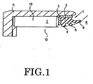
- Fig. 1 is a half sectional view illustrating a sealing apparatus 1 and a peripheral portion thereof according to the first embodiment.
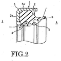
- Fig. 2 is a half sectional view illustrating the sealing apparatus 1 according to the first embodiment.
- a propeller shaft (universal joint) of Fig. 1
- an end portion of a cross shaft 12 is inserted and fitted to a cylindrical cap 11 having a bottom.
- a plurality of needle-shaped bearings 13 are rotatably arranged between the outer periphery of the end portion of cross shaft 12 and the inner periphery of cap 11.
- Grease supply that supplies grease by providing a passageway in cross shaft 12 is carried out in this bearing 13.
- sealing apparatus 1 is arranged in an annular gap between the inner periphery of the open end portion of cap 11 and the outer periphery of cross shaft 12 with this bearing 13 side serving as an inner side I. Then, the side of sealing apparatus 1 opposite to the inner side I of the bearing 13 side is referred to as an open-air side A that is open to the outside of the apparatus.
- Sealing apparatus 1 is attached to cap 11 and has a construction such that various lips are slidably in contact with cross shaft 12.
- Sealing apparatus 1 is substantially made of rubber-like elastic substance or made of resin, and is constituted of an attachment portion 2, a sealing lip 4, and two dust lips 5, 6.
- Attachment portion 2 is attached by integrally forming a metal ring 3 on the outer peripheral surface and the inner side I surface and metal ring 3 is fitted by press-fitting on the inner peripheral surface of the open end portion of cap 11.
- Metal ring 3 is constituted of a cylindrical portion 3a that goes along the inner peripheral surface of the open end portion of cap 11 and an annular portion 3b that extends in the inner radius direction from the inner side end of cylindrical portion 3a. Annular portion 3b is adjacent to bearings 13 so as to guide the needle-shaped bearings 13.
- Sealing lip 4 is the lip of the innermost side I of sealing apparatus 1, namely a lip on the side near to bearings 13, and extends to cross shaft 12 from attachment portion 2 in the middle direction of the inner side I and the open-air side A, namely in the direction perpendicular to the axial direction from the inner side I to the open-air side A, to be slidably in sealing contact with cross shaft 12.
- the inner side contact angle ⁇ refers to the angle that the tip end of the tilted inner side I surface of the lip cross-section of sealing lip 4 forms with the axial direction from the inner side I to the open-air side A in which cross shaft 12 extends.
- the open-air side contact angle ⁇ refers to the angle that the tip end of the tilted open-air side A surface of the lip cross-section of sealing lip 4 forms with the axial direction from the inner side I to the open-air side A in which cross shaft 12 extends.
- Two dust lips 5, 6 extend to cross shaft 12 while being tilted to the open-air side A from attachment portion 2 on the open-air side A of sealing lip 4 to be slidably in contact with cross shaft 12.
- dust lips 5, 6 are a double seal having two parts, penetration of dusts can be prevented and the sealing property is enhanced to a greater extent.
- sealing apparatus 1 having the above-described construction, leakage of grease in the inside is prevented by the sectional shape of sealing lip 4 whose tip end is formed to be a triangular lip, so that the grease resistance property is improved.
- sealing lip 4 is at the middle of the inner side I and the open-air side A, occurrence of a defect such as lip inversion caused by generation of inner pressure is prevented.
- Fig. 3 illustrates one that is provided to be a so-called inverse offset lip in which the inner side contact angle ⁇ of the tip end of sealing lip 4 is an angle larger than the open-air side contact angle ⁇ ( ⁇ > ⁇ ).
- Fig. 3 is a half sectional view illustrating a sealing apparatus 1 according to the explanatory example.
- the same constituents described in the first embodiment will be denoted with the same symbols, and the description thereof will be omitted.
- sealing lip 4 is tilted from attachment portion 2 to the open-air side A and extends to cross shaft 12 to be slidably in sealing contact with cross shaft 12.
- the sectional shape of sealing lip 4 whose tip end is formed to be an inverse offset lip prevents leakage of grease in the inside, so that the grease resistance property is improved. Moreover, since it has a shape similar to a so-called inward-oriented lip, the grease resistance property is improved to a greater extent than with the sectional shape of sealing lip 4 of Fig. 2 .
- Fig. 4 is a half sectional view illustrating a sealing apparatus 1 according to the second embodiment. The same constituents as described above will be denoted with the same symbols, and the description thereof will be omitted.
- sealing lip 4 extends from the base to cross shaft 12 in the middle direction of the inner side I and the open-air side A so as to be slidably in sealing contact with cross shaft 12.
- sealing lip 4 has an inner side contact angle ⁇ being equal to an open-air side contact angle ⁇ , has a direction extending from the base being the middle of the inner side I and the open-air side A, and has a sectional shape of a triangular lip which is symmetric relative to the line of this middle direction.
- sealing apparatus 1 having a construction of Fig. 4 , the sectional shape of sealing lip 4 formed to be a triangular lip from the base prevents leakage of grease in the inside, so that the grease resistance property is improved.
- sealing lip 4 is at the middle of the inner side I and the open-air side A, occurrence of a defect such as lip inversion caused by generation of inner pressure is prevented.
- the total shape of the sealing lip 4 such as illustrated in Fig. 4 enhances the rigidity of sealing lip 4, restrains the fluctuation of the angles of the inner side contact angle ⁇ and the open-air side contact angle ⁇ caused by deformation of sealing lip 4, and can stabilize the sealing property. Also, enhancement of the rigidity of sealing lip 4 further prevents occurrence of a defect such as inversion of the lip caused by generation of inner pressure.
Landscapes
- Engineering & Computer Science (AREA)
- General Engineering & Computer Science (AREA)
- Mechanical Engineering (AREA)
- Sealing With Elastic Sealing Lips (AREA)
- Sealing Of Bearings (AREA)
Claims (4)
- Dichtungsanordnung für ein Universalgelenk mit:zwei Bauteilen (11, 12),einem Anbringungsabschnitt (2), der einstückig mit einem Metallring (3) mit einem zylindrischen Abschnitt (3a) und einem ringförmigen Abschnitt (3b) ausgebildet ist und an einem Bauteil (11) der zwei Bauteile (11, 12) angebracht ist, die zueinander relativ bewegbar angeordnet sind, wobei das eine Bauteil (11) eine Abdeckung (11) ist und das andere Bauteil eine Welle (12) ist, und wobei die Welle (12) in die Abdeckung (11) eingesetzt ist und durch ein Lager (13) drehbar gestützt ist, das zwischen der Welle (11) und der Abdeckung (4) angeordnet ist;einer Dichtungslippe (4), die sich von dem Anbringungsabschnitt (2) zu der Welle (12) erstreckt, um mit der Welle (12) gleitbar in einem Dichtungskontakt zu sein; undeiner Staublippe (5, 6), die sich zu der Welle (12) erstreckt, um mit der Welle (12) gleitbar in Kontakt zu sein, während sie in Richtung der Freiluftseite (A) von dem Anbringungsabschnitt (2) an der Freiluftseite (A) der Dichtungslippe (4) geneigt ist,wobei ein innenseitiger Kontaktwinkel (α) und ein freiluftseitiger Kontaktwinkel (β) der Dichtungslippe (4) zwischen der Dichtungslippe (4) und einer Fläche der Welle (12) definiert sind, an der der Dichtungskontakt erfolgt, undwobei der ringförmige Abschnitt (3b) benachbart zu dem Lager (13) ist, um das Lager (13) zu führen,dadurch gekennzeichnet, dassder innenseitige Kontaktwinkel (α) gleich dem freiluftseitigen Kontaktwinkel (β) ist.
- Dichtungsanordnung nach Anspruch 1, wobei sich die Dichtungslippe (4) von dem Anbringungsabschnitt (2) im Wesentlichen senkrecht in Richtung des Dichtungskontakts erstreckt oder sich von dem Anbringungsabschnitt (2) in Richtung der Freiluftseite (A) in Bezug auf die senkrechte Richtung erstreckt.
- Dichtungsanordnung nach Anspruch 1 oder 2, wobei die Staublippe (5, 6) eine Doppeldichtung mit zwei Bestandteilen (5, 6) ist.
- Dichtungsanordnung nach Anspruch 1, 2 oder 3, wobei die Dichtungslippe (4) die Erstreckungsrichtung hat, die sich im Wesentlichen senkrecht in Richtung des Dichtungskontakts erstreckt, und eine Querschnittsform hat, die symmetrisch zu der Linie der Erstreckungsrichtung ist.
Applications Claiming Priority (3)
| Application Number | Priority Date | Filing Date | Title |
|---|---|---|---|
| JP2002262620 | 2002-09-09 | ||
| JP2002262620 | 2002-09-09 | ||
| PCT/JP2003/011434 WO2004023007A1 (ja) | 2002-09-09 | 2003-09-08 | 密封装置 |
Publications (3)
| Publication Number | Publication Date |
|---|---|
| EP1538376A1 EP1538376A1 (de) | 2005-06-08 |
| EP1538376A4 EP1538376A4 (de) | 2006-02-15 |
| EP1538376B1 true EP1538376B1 (de) | 2008-11-19 |
Family
ID=31973163
Family Applications (1)
| Application Number | Title | Priority Date | Filing Date |
|---|---|---|---|
| EP03794283A Expired - Lifetime EP1538376B1 (de) | 2002-09-09 | 2003-09-08 | Dichtungsvorrichtung |
Country Status (8)
| Country | Link |
|---|---|
| US (2) | US20050272508A1 (de) |
| EP (1) | EP1538376B1 (de) |
| JP (1) | JPWO2004023007A1 (de) |
| KR (1) | KR20050057277A (de) |
| CN (1) | CN100417848C (de) |
| AU (1) | AU2003261994A1 (de) |
| DE (1) | DE60324807D1 (de) |
| WO (1) | WO2004023007A1 (de) |
Families Citing this family (13)
| Publication number | Priority date | Publication date | Assignee | Title |
|---|---|---|---|---|
| JP5348365B2 (ja) * | 2007-10-12 | 2013-11-20 | Nok株式会社 | ユニバーサルジョイント用密封装置 |
| US7926819B2 (en) * | 2008-08-25 | 2011-04-19 | GM Global Technology Operations LLC | Seals for transmission drive motors |
| US8414215B2 (en) * | 2008-11-07 | 2013-04-09 | Trw Automotive U.S. Llc | Sealing structure for use with a ball and socket joint |
| CN102439324B (zh) * | 2009-05-25 | 2014-09-24 | Skf公司 | 特别是应用于农业的轴承密封组件 |
| CN102297266A (zh) * | 2011-07-28 | 2011-12-28 | 王茂 | 盾构机大直径双重密封结构 |
| WO2013142193A1 (en) | 2012-03-20 | 2013-09-26 | Schaeffler Technologies AG & Co. KG | Sealed bearing with compact static outer diameter seal |
| JP6117000B2 (ja) * | 2013-05-24 | 2017-04-19 | Nok株式会社 | ピストン一体シール |
| DE102015220962B4 (de) * | 2015-10-27 | 2022-06-30 | Aktiebolaget Skf | Lageranordnung mit Vorspannung |
| US10612660B2 (en) | 2016-02-03 | 2020-04-07 | Nok Corporation | Gasket |
| US10288199B2 (en) * | 2016-05-11 | 2019-05-14 | Mcwane, Inc. | Restrained plastic pipe joint and method of making same |
| DE102017205270A1 (de) * | 2017-02-09 | 2018-09-20 | Aktiebolaget Skf | Kreuzgelenklager |
| TWI670434B (zh) * | 2017-11-13 | 2019-09-01 | 龔婉蓉 | 密封件 |
| WO2021079585A1 (ja) * | 2019-10-21 | 2021-04-29 | Nok株式会社 | ガスケット |
Citations (2)
| Publication number | Priority date | Publication date | Assignee | Title |
|---|---|---|---|---|
| US4449718A (en) * | 1982-07-10 | 1984-05-22 | Busak & Luyken | Packing for hydraulic pistons or piston rods |
| JPH11125338A (ja) * | 1997-10-24 | 1999-05-11 | Nok Corp | オイルシール |
Family Cites Families (30)
| Publication number | Priority date | Publication date | Assignee | Title |
|---|---|---|---|---|
| DE1264170B (de) * | 1963-04-05 | 1968-03-21 | Goetzewerke | Abdichtung fuer Rollenlager in Kraftfahrzeugradnaben |
| US3200615A (en) * | 1963-08-14 | 1965-08-17 | Borg Warner | Sealing element |
| US3455564A (en) * | 1967-01-26 | 1969-07-15 | Gen Motors Corp | High pressure lip seal |
| US3479840A (en) | 1968-04-16 | 1969-11-25 | Dana Corp | Trunnion seal for cardan-type universal joint |
| US3572730A (en) * | 1969-06-13 | 1971-03-30 | Timken Co | Wear surface for facilitating lubrication of elements in engagement therewith |
| DE7006022U (de) | 1970-02-19 | 1970-06-18 | Gelenkwellenbau Gmbh | Wellenabdichtung. |
| US4427206A (en) * | 1982-07-20 | 1984-01-24 | Keeper Co., Ltd. | Oil seal assembly with unbonded backup ring |
| US5244215A (en) * | 1985-05-10 | 1993-09-14 | Chicago Rawhide Manufacturing Company | Rotary shaft seal with retractable excluder lip |
| DE8705291U1 (de) * | 1987-04-09 | 1987-05-27 | SKF GmbH, 8720 Schweinfurt | Abdichtung für Lagerbüchsen, insbesondere für Kreuzgelenke |
| DE3723654A1 (de) * | 1987-07-17 | 1989-01-26 | Stabilus Gmbh | Schwimmend angeordneter dichtring mit ventilfunktion |
| DE8805833U1 (de) * | 1988-05-03 | 1988-07-21 | SKF GmbH, 8720 Schweinfurt | Dichtungsring für Lager, insbesondere für Lagerbüchsen von Kreuzgelenken |
| DE3828692A1 (de) * | 1988-08-24 | 1990-03-15 | Busak & Luyken Gmbh & Co | Anordnung zum abdichten einer hin- und herbewegten stange |
| DE4041498A1 (de) * | 1990-12-22 | 1992-06-25 | Zahnradfabrik Friedrichshafen | Dichtung fuer ein zapfenkreuzlager |
| JP3180285B2 (ja) * | 1994-03-11 | 2001-06-25 | エヌオーケー株式会社 | オイルシール |
| US5478091A (en) * | 1994-04-07 | 1995-12-26 | Imo Industries, Inc. | Dynamic seal and related control cable |
| DE4412132C5 (de) * | 1994-04-08 | 2005-07-28 | Ina-Schaeffler Kg | Abdichtung für eine Gelenkkreuzbüchse |
| US5588915A (en) * | 1995-12-26 | 1996-12-31 | Dana Corporation | Seal and seal guard assembly for universal joint |
| US6045138A (en) * | 1996-04-24 | 2000-04-04 | Nok Corporation | Sealing device for reciprocal movement |
| JPH09292031A (ja) * | 1996-04-24 | 1997-11-11 | Nok Corp | 往復動用密封装置 |
| JP3358940B2 (ja) * | 1996-06-17 | 2002-12-24 | 三菱重工業株式会社 | 石炭灰の利用システム |
| EP0939257A3 (de) * | 1998-02-27 | 2000-05-31 | NOK Corporation | Radialwellendichtung |
| US6050899A (en) * | 1998-05-15 | 2000-04-18 | Neapco, Inc. | Sealing system for a universal joint assembly |
| JP4244442B2 (ja) * | 1998-06-12 | 2009-03-25 | Nok株式会社 | 密封装置 |
| US6736404B1 (en) * | 1999-11-04 | 2004-05-18 | Dana Corporation | Shaft for use with annular seal assembly and method of manufacturing same |
| DE10019994A1 (de) * | 2000-04-22 | 2001-10-31 | Freudenberg Carl Fa | Radialwellendichtring |
| JP2002098163A (ja) * | 2000-09-20 | 2002-04-05 | Koyo Seiko Co Ltd | ユニバーサルジョイントの密封装置 |
| JP2002106594A (ja) * | 2000-09-28 | 2002-04-10 | Koyo Seiko Co Ltd | ユニバーサルジョイント |
| JP2002188730A (ja) * | 2000-12-25 | 2002-07-05 | Showa Corp | 往復動用オイルシールのダストリップ構造 |
| DE10102302A1 (de) * | 2001-01-19 | 2002-08-01 | Elbe & Sohn Gmbh & Co Kg G | Dichtungssystem für Kreuzgelenke bzw. Doppelkreuzgelenke |
| US6997461B2 (en) * | 2001-07-17 | 2006-02-14 | Trelleborg Sealing Solutions U.S., Inc. | High speed high pressure rotary |
-
2003
- 2003-09-08 KR KR1020057003988A patent/KR20050057277A/ko not_active Ceased
- 2003-09-08 US US10/527,027 patent/US20050272508A1/en not_active Abandoned
- 2003-09-08 EP EP03794283A patent/EP1538376B1/de not_active Expired - Lifetime
- 2003-09-08 CN CNB038244926A patent/CN100417848C/zh not_active Expired - Fee Related
- 2003-09-08 WO PCT/JP2003/011434 patent/WO2004023007A1/ja not_active Ceased
- 2003-09-08 DE DE60324807T patent/DE60324807D1/de not_active Expired - Lifetime
- 2003-09-08 JP JP2004534191A patent/JPWO2004023007A1/ja active Pending
- 2003-09-08 AU AU2003261994A patent/AU2003261994A1/en not_active Abandoned
-
2007
- 2007-04-20 US US11/785,833 patent/US7465100B2/en not_active Expired - Lifetime
Patent Citations (2)
| Publication number | Priority date | Publication date | Assignee | Title |
|---|---|---|---|---|
| US4449718A (en) * | 1982-07-10 | 1984-05-22 | Busak & Luyken | Packing for hydraulic pistons or piston rods |
| JPH11125338A (ja) * | 1997-10-24 | 1999-05-11 | Nok Corp | オイルシール |
Also Published As
| Publication number | Publication date |
|---|---|
| KR20050057277A (ko) | 2005-06-16 |
| DE60324807D1 (de) | 2009-01-02 |
| US7465100B2 (en) | 2008-12-16 |
| WO2004023007A1 (ja) | 2004-03-18 |
| CN1688833A (zh) | 2005-10-26 |
| US20050272508A1 (en) | 2005-12-08 |
| US20070197302A1 (en) | 2007-08-23 |
| CN100417848C (zh) | 2008-09-10 |
| AU2003261994A1 (en) | 2004-03-29 |
| EP1538376A1 (de) | 2005-06-08 |
| JPWO2004023007A1 (ja) | 2005-12-22 |
| EP1538376A4 (de) | 2006-02-15 |
Similar Documents
| Publication | Publication Date | Title |
|---|---|---|
| US7465100B2 (en) | Sealing apparatus | |
| JP4934943B2 (ja) | 軸用リップパッキン | |
| EP3351833B1 (de) | Abdichtungsvorrichtung für differenzialmechanismus | |
| US20100066030A1 (en) | Hermetic sealing device | |
| US20110091143A1 (en) | Spherical bearing triple-lip seal | |
| EP3244100A1 (de) | Dichtungsvorrichtung | |
| EP0194810A2 (de) | Flüssigkeitsabdichtung für Walzgerüste | |
| US8328650B2 (en) | Constant velocity universal joint | |
| JPH0252140B2 (de) | ||
| US20050173869A1 (en) | Spark plug tube seal | |
| CN212251132U (zh) | 密封装置 | |
| US20220142733A1 (en) | Roller bearing | |
| US20180073556A1 (en) | Universal joint including a seal, seal, and method for installing a seal | |
| JP5534733B2 (ja) | 自在継手用ブーツ | |
| US7357725B2 (en) | Boot for constant velocity universal joint | |
| JP4399930B2 (ja) | 密封装置 | |
| JP7455711B2 (ja) | オイルシール | |
| US20180363708A1 (en) | Cardan universal joint seal with optimized lip orientations | |
| JP4851114B2 (ja) | 密封型転がり軸受 | |
| US11835136B2 (en) | Sealing device | |
| JP4506262B2 (ja) | 転がり軸受ユニットの密封手段転がり軸受ユニット | |
| JP2010060120A (ja) | 密封装置 | |
| JP2017089701A (ja) | 密封装置 | |
| JPH09250642A (ja) | 密封装置 | |
| US20080012238A1 (en) | Method of retaining a dynamic seal in a bore that has a draft |
Legal Events
| Date | Code | Title | Description |
|---|---|---|---|
| PUAI | Public reference made under article 153(3) epc to a published international application that has entered the european phase |
Free format text: ORIGINAL CODE: 0009012 |
|
| 17P | Request for examination filed |
Effective date: 20050308 |
|
| AK | Designated contracting states |
Kind code of ref document: A1 Designated state(s): AT BE BG CH CY CZ DE DK EE ES FI FR GB GR HU IE IT LI LU MC NL PT RO SE SI SK TR |
|
| AX | Request for extension of the european patent |
Extension state: AL LT LV MK |
|
| DAX | Request for extension of the european patent (deleted) | ||
| RBV | Designated contracting states (corrected) |
Designated state(s): DE FR GB |
|
| A4 | Supplementary search report drawn up and despatched |
Effective date: 20060104 |
|
| 17Q | First examination report despatched |
Effective date: 20060411 |
|
| GRAP | Despatch of communication of intention to grant a patent |
Free format text: ORIGINAL CODE: EPIDOSNIGR1 |
|
| GRAS | Grant fee paid |
Free format text: ORIGINAL CODE: EPIDOSNIGR3 |
|
| GRAA | (expected) grant |
Free format text: ORIGINAL CODE: 0009210 |
|
| AK | Designated contracting states |
Kind code of ref document: B1 Designated state(s): DE FR GB |
|
| REG | Reference to a national code |
Ref country code: GB Ref legal event code: FG4D |
|
| REF | Corresponds to: |
Ref document number: 60324807 Country of ref document: DE Date of ref document: 20090102 Kind code of ref document: P |
|
| PLBE | No opposition filed within time limit |
Free format text: ORIGINAL CODE: 0009261 |
|
| STAA | Information on the status of an ep patent application or granted ep patent |
Free format text: STATUS: NO OPPOSITION FILED WITHIN TIME LIMIT |
|
| 26N | No opposition filed |
Effective date: 20090820 |
|
| PGFP | Annual fee paid to national office [announced via postgrant information from national office to epo] |
Ref country code: GB Payment date: 20090902 Year of fee payment: 7 |
|
| PGFP | Annual fee paid to national office [announced via postgrant information from national office to epo] |
Ref country code: DE Payment date: 20090903 Year of fee payment: 7 |
|
| PGFP | Annual fee paid to national office [announced via postgrant information from national office to epo] |
Ref country code: FR Payment date: 20091012 Year of fee payment: 7 |
|
| GBPC | Gb: european patent ceased through non-payment of renewal fee |
Effective date: 20100908 |
|
| REG | Reference to a national code |
Ref country code: FR Ref legal event code: ST Effective date: 20110531 |
|
| REG | Reference to a national code |
Ref country code: DE Ref legal event code: R119 Ref document number: 60324807 Country of ref document: DE Effective date: 20110401 |
|
| PG25 | Lapsed in a contracting state [announced via postgrant information from national office to epo] |
Ref country code: FR Free format text: LAPSE BECAUSE OF NON-PAYMENT OF DUE FEES Effective date: 20100930 Ref country code: DE Free format text: LAPSE BECAUSE OF NON-PAYMENT OF DUE FEES Effective date: 20110401 |
|
| PG25 | Lapsed in a contracting state [announced via postgrant information from national office to epo] |
Ref country code: GB Free format text: LAPSE BECAUSE OF NON-PAYMENT OF DUE FEES Effective date: 20100908 |