EP1538299A1 - Vorrichtung zum Aufwickeln eines Gurts für einen Rollladen und Verfahren zur Herstellung desselben - Google Patents
Vorrichtung zum Aufwickeln eines Gurts für einen Rollladen und Verfahren zur Herstellung desselben Download PDFInfo
- Publication number
- EP1538299A1 EP1538299A1 EP03027649A EP03027649A EP1538299A1 EP 1538299 A1 EP1538299 A1 EP 1538299A1 EP 03027649 A EP03027649 A EP 03027649A EP 03027649 A EP03027649 A EP 03027649A EP 1538299 A1 EP1538299 A1 EP 1538299A1
- Authority
- EP
- European Patent Office
- Prior art keywords
- carrier plate
- belt
- plate portion
- plate section
- holding arm
- Prior art date
- Legal status (The legal status is an assumption and is not a legal conclusion. Google has not performed a legal analysis and makes no representation as to the accuracy of the status listed.)
- Granted
Links
- 238000004519 manufacturing process Methods 0.000 title abstract description 19
- 238000000034 method Methods 0.000 title abstract description 4
- 238000004804 winding Methods 0.000 abstract description 10
- 230000002093 peripheral effect Effects 0.000 description 6
- 239000002184 metal Substances 0.000 description 5
- 150000001875 compounds Chemical class 0.000 description 1
- 238000002788 crimping Methods 0.000 description 1
- 238000005304 joining Methods 0.000 description 1
Images



Classifications
-
- E—FIXED CONSTRUCTIONS
- E06—DOORS, WINDOWS, SHUTTERS, OR ROLLER BLINDS IN GENERAL; LADDERS
- E06B—FIXED OR MOVABLE CLOSURES FOR OPENINGS IN BUILDINGS, VEHICLES, FENCES OR LIKE ENCLOSURES IN GENERAL, e.g. DOORS, WINDOWS, BLINDS, GATES
- E06B9/00—Screening or protective devices for wall or similar openings, with or without operating or securing mechanisms; Closures of similar construction
- E06B9/56—Operating, guiding or securing devices or arrangements for roll-type closures; Spring drums; Tape drums; Counterweighting arrangements therefor
- E06B9/78—Operating, guiding or securing devices or arrangements for roll-type closures; Spring drums; Tape drums; Counterweighting arrangements therefor for direct manual operation, e.g. by tassels, by handles
Definitions
- the invention relates to a device for winding a Belts for a roller shutter according to the preamble of the claim 1. It also relates to a method for producing a such device.
- From DE 201 04 830.2 is a device for winding a belt known for a roller shutter. Extend itself from a one-piece carrier plate two Retaining arms, on which rotatably a belt drum for winding the belt is attached. - In practice, depending on the length of the belt to be wound several devices with different Sizes offered. Distinguish the devices u.a. also in the length of the carrier plate. For the production of devices with support plates of different Length must each have a suitable special tool to be provided. This causes a high production cost. It is intended in particular a device for Winding a belt for a roller shutter, which can be produced with reduced effort. additional The aim of the invention is the indication of a simple and inexpensive feasible method for producing a Device for winding a belt for a roller shutter.
- the carrier plate from a first carrier plate portion and a so connected second carrier plate section made is, so that from the first and the second support plate portion formed carrier plate a predetermined length having.
- the first carrier plate portion may have a first length and the second carrier plate portion of a plurality held in different second lengths be selected second carrier plate sections. With a first tool, the first carrier plate section can be produced become. With a second tool can simultaneously several second carrier plate sections in different second lengths are produced.
- a second carrier plate section with a suitable second length at the first Mount support plate portion so that the resulting Support plate has the predetermined length. This is it is possible to use only two tools for winding a belt for a roller shutter, where the carrier plate a variety of different Lengths may have.
- the first carrier plate section Component of at least one holding arm for receiving the belt drum assembly unit.
- the first carrier plate portion and the holding arm be made in one-piece training.
- the holding arm may have a plurality of second apertures, which attaching a belt drum rotatably receiving the axis in different Positions possible.
- the proposed Mounting unit is relatively complex.
- the second carrier plate section can be particularly simple, for example, in the form of a simple sheet executed his.
- the tool for producing the second carrier plate section Can run relatively easily and inexpensively his.
- the mounting unit must be used to provide devices not changed with carrier plates in different lengths become. It is only necessary to second Carrier plate sections in the respectively suitable second Length to install. This further simplifies the production. It can with comparatively little effort depending on the customer requirement Devices with a predetermined length of the support plate be made quickly and inexpensively.
- suitable second carrier plate sections to connect with the mounting unit.
- the belt drum has a protruding from the peripheral surface and in one piece Training thus produced tab for attaching the Gurts on.
- This feature also simplifies the manufacture. In departure from the prior art, it is no longer necessary a movably held in a recess of the peripheral surface To mount retaining element for fastening the belt.
- the second carrier plate section by means of a riveted joint on the mounting unit appropriate.
- a riveted connection can be simple and manufactured inexpensively.
- the second carrier plate section by means conventional other joining techniques, such as riveting, Crimp or snap connections to attach to the mounting unit.
- the second carrier plate portion in the form of a formed first carrier plate portion overlapping aperture.
- the aperture is through the replaced second carrier plate section.
- the second carrier plate section in this case covers the first carrier plate section; he has a breakthrough, which with the z. B. provided in the first carrier plate portion first Breakthrough to carry the belt in alignment is.
- the bezel can be made of metal or plastic his. It can with the mounting unit by means of a suitable Riveting, crimping or locking connection be connected.
- a method for Production of a generic device for winding a belt provided for a roller shutter wherein the support plate by connecting a first carrier plate portion and a second carrier plate section is produced, so that from the first and the second support plate section formed carrier plate has a predetermined length.
- a first tool serves z.
- B. the production of a first carrier plate section comprehensive unity and a second - relative easy to use - tool is used to make the second carrier plate section. It eliminates the need for each device with a different length the carrier plate a special, consuming to produce To provide tools.
- the first carrier plate section a first length and the second carrier plate portion is made up of a plurality of in different second lengths held second carrier plate sections selected.
- the second carrier plate sections can be kept in several length classes. Such length classes can be in a single tool be produced simultaneously. In this case, a second carrier plate section of one of the length classes be selected before attaching to the mounting unit.
- the first carrier plate section is expediently part a at least one holding arm for receiving the Belt drum comprehensive assembly unit.
- the first carrier plate section and the arm can be in one piece training getting produced.
- the arm can with several second Breakthroughs are provided, which attaching a the belt drum rotatably receiving axis in different Positions possible.
- the proposed assembly unit is very universal. It is suitable for recording Belt drums of different diameters.
- the belt drum Depending on the requirement, it can be placed in different positions on the support arm be attached.
- the second carrier plate portion by means of a riveted joint attached to the mounting unit.
- a riveted joint attached to the mounting unit.
- the riveted joint a conventional other compound to use, for example, a screw, squeeze or Locking connection.
- the belt drum can be used before or after making the connection between the first and second support plate sections be attached to the support arm.
- the peripheral surface is cylindrical and consists in this case made of sheet metal.
- the second carrier plate section in an array extending from one end of the aperture attached to the mounting unit.
- the location of the attachment points of the second carrier plate portion remains unchanged on the mounting unit. That makes it easier an automated attachment of the second carrier plate portion on the mounting unit. It is also conceivable that second carrier plate portion for realizing a different Length of the carrier plates in different positions to be attached to the mounting unit.
- the second carrier plate portion in the form of a first carrier plate portion formed covering cover.
- the second carrier plate portion may be on a special aperture, as after the Prior art used to cover the carrier plate will be waived. This saves manufacturing and assembly costs.
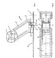
- Figs. 1 and 2 show a first device for winding a Gurts G for roller shutters.
- a belt drum 7a and one on top recorded belt G are in these figures for clarity not shown.
- first carrier plate portion 1 extends in one-piece training a holding arm 2.
- the first carrier plate section 1 has next to the support arm 2 a first breakthrough 3 for the implementation of the (not shown here) belt G on.
- a first breakthrough 3 limiting stop 4 is opposite to a pivotally held about an axis 5 Gurt Adjustselement 6.
- the support arm 2 has two slots 7th for receiving an (not shown here) axis of (also not shown) belt drum 7a.
- the first carrier plate section 1 forms together with the holding arm 2 a Mounting unit M.
- a second support plate portion 9 is attached.
- the second carrier plate portion 9 is thus at the first Carrier plate section 1 attached that he from the an end of the first opening 3 in alignment with the first carrier plate portion 1 extends.
- Figs. 3 and 4 show a second device for Aufwikkeln a belt G for roller shutters.
- the second device is similar to the device shown in Figs. 1 and 2 executed. However, it has two opposite ones Holding arms 2 on.
- the first breakthrough 3 is through the two Holding arms 2 limited.
- Fig. 3 is a schematic to the Holding arms 2 rotatably recorded belt drum 7a shown.
- On the reel drum 7a is integrally formed by the peripheral surface thereof extending strap 7b a belt G attached which through the first breakthrough 3 and over the Gurt Resultsselement 6 is guided.
- the belt G has a (not shown here) breakthrough, with which he at the tab 7b is attached.
- the tab 7b can be an undercut Having shape, so that the belt G is not easy from the tab 7b can solve.
- the mounting unit M can also include the assembled reel drum 7a.
- Fig. 5 shows a plan view of second support plate sections 9.
- the second carrier plate sections 9 each have third openings 10 for producing the riveted joint 8 on.
- the third openings 10 are square and have rounded corners.
- the out of the first 1 and the second support plate portion 9 formed Support plate 4 has four different lengths.
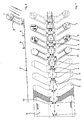
- Figs. 6 and 7 show the manufacturing steps in the Fig. 3 and 4 shown assembly unit M.
- a first Step are from a supplied strip B the third Breakthroughs 10, further breakthroughs and the contour of the retaining arms 2 punched out.
- the first Breakthrough 3 is created and in a third step the first breakthrough 3 limiting stop 4 with a Vaulting provided.
- stiffening structures become 11, in particular in the region of the retaining arms 2 and the first carrier plate section 1.
- the stopper 4 is bent over and thus the first breakthrough 3 opened.
- the second Breakthroughs 7 punched in the region of the support arms 2.
- the holding arms 2 are bent over and the mounting unit M separated from the sheet B.
- Fig. 8 shows a plan view of manufacturing variants of second support plate section 9.
- the marginal notches 12 mark different positions where the Sheet metal strip B for the production of second support plate sections 9 can be separated in different lengths.
- the second carrier plate portion 9 can not only in shape made of a mounting unit M extending sheet metal section be, but also as a shutter. In this (here not shown) case, the second carrier plate portion extends 9 also over the first carrier plate section. 1 He is, for example, with a rivet 8 on the mounting unit M attached. Also in this case, the second Carrier plate portion 9 held in different lengths be, so that still using the Mounting unit M Devices for winding a belt G can be provided, the support plate a different Length.
Landscapes
- Engineering & Computer Science (AREA)
- Structural Engineering (AREA)
- Architecture (AREA)
- Civil Engineering (AREA)
- Operating, Guiding And Securing Of Roll- Type Closing Members (AREA)
- Storage Of Web-Like Or Filamentary Materials (AREA)
- Basic Packing Technique (AREA)
- Winding Of Webs (AREA)
Abstract
Description
- Fig. 1
- eine Seitenansicht einer ersten erfindungsgemäßen Vorrichtung,
- Fig. 2
- eine Draufsicht nach Fig. 1,
- Fig. 3
- eine Seitenansicht einer zweiten erfindungsgemäßen Vorrichtung,
- Fig. 4
- eine Draufsicht nach Fig. 3,
- Fig. 5
- eine Draufsicht auf mehrere Ausführungsformen eines zweiten Trägerplattenabschnitts,
- Fig. 6
- eine Seitenansicht der Herstellungsschritte einer Montageeinheit gemäß den Fig. 3 und 4,
- Fig. 7
- eine Draufsicht nach Fig. 5 und
- Fig. 8
- eine Draufsicht auf Herstellungsvarianten eines zweiten Trägerplattenabschnitts.
- 1
- erster Trägerplattenabschnitt
- 2
- Haltearm
- 3
- erster Durchbruch
- 4
- Anschlag
- 5
- Achse
- 6
- Gurtführungselement
- 7
- Langloch
- 7a
- Gurttrommel
- 7b
- Lasche
- 8
- Nietverbindung
- 9
- zweiter Trägerplattenabschnitt
- 10
- dritte Durchbruch
- 11
- Versteifungsstruktur
- 12
- Einkerbung
- B
- Blechband
- G
- Gurt
- M
- Montageeinheit
Claims (19)
- Vorrichtung zum Aufwickeln eines Gurts (G) für einen Rollladen, wobei an einer einen ersten Durchbruch (3) zum Durchführen des Gurts (G) aufweisenden Trägerplatte eine Gurttrommel (7a) zur Aufnahme des Gurts (G) angebracht ist,
dadurch gekennzeichnet, dass
die Trägerplatte aus einem ersten Trägerplattenabschnitt (1) und einem damit verbundenen zweiten Trägerplattenabschnitt (9) hergestellt ist, so dass die aus dem ersten (1) und dem zweiten Trägerplattenabschnitt (9) gebildete Trägerplatte eine vorgegebene Länge aufweist. - Vorrichtung nach Anspruch 1, wobei der erste Trägerplattenabschnitt (1) eine erste Länge aufweist und der zweite Trägerplattenabschnitt (9) aus einer Mehrzahl von in unterschiedlichen zweiten Längen vorgehaltenen zweiten Trägerplattenabschnitten (9) ausgewählt ist.
- Vorrichtung nach einem der vorhergehenden Ansprüche, wobei der erste Trägerplattenabschnitt (1) Bestandteil einer mindestens einen Haltearm (2) zur Aufnahme der Gurttrommel (7a) umfassenden Montageeinheit (M) ist.
- Vorrichtung nach einem der vorhergehenden Ansprüche, wobei der erste Trägerplattenabschnitt (1) und der Haltearm (2) in einstückiger Ausbildung hergestellt sind.
- Vorrichtung nach einem der vorhergehenden Ansprüche, wobei der Haltearm (2) mehrere zweite Durchbrüche (7) aufweist, welche ein Anbringen einer die Gurttrommel (7a) drehbar aufnehmenden Achse (5) in unterschiedlichen Positionen ermöglichen.
- Vorrichtung nach einem der vorhergehenden Ansprüche, wobei die Gurttrommel (7a) eine aus deren Umfangsfläche hervorstehende und in einstückiger Ausbildung damit hergestellte Lasche (7b) zur Befestigung des Gurts (G) aufweist.
- Vorrichtung nach einem der vorhergehenden Ansprüche, wobei der zweite Trägerplattenabschnitt (9) mittels einer Nietverbindung (8) an der Montageeinheit (M) angebracht ist.
- Vorrichtung nach einem der vorhergehenden Ansprüche, wobei der zweite Trägerplattenabschnitt (9) sich vom einen Ende des ersten Durchbruchs (3) erstreckt.
- Vorrichtung nach einem der vorhergehenden Ansprüche, wobei der zweite Trägerplattenabschnitt (9) in Form einer den ersten Trägerplattenabschnitt (1) überdeckenden Blende ausgebildet ist.
- Verfahren zur Herstellung einer Vorrichtung zum Aufwikkeln eines Gurts (G) für einen Rollladen, wobei an einer einen ersten Durchbruch (3) zum Durchführen des Gurts (G) aufweisenden Trägerplatte eine Gurttrommel (7a) zur Aufnahme des Gurts (G) angebracht ist,
dadurch gekennzeichnet, dass
die Trägerplatte durch Verbinden eines ersten Trägerplattenabschnitts (1) und eines zweiten Trägerplattenabschnitts (9) hergestellt wird, so dass die aus dem ersten (1) und dem zweiten Trägerplattenabschnitt (9) gebildete Trägerplatte eine vorgegebene Länge aufweist. - Verfahren nach Anspruch 10, wobei der erste Trägerplattenabschnitt (1) eine erste Länge aufweist und der zweite Trägerplattenabschnitt (9) aus einer Mehrzahl von in unterschiedlichen zweiten Längen vorgehaltenen zweiten Trägerplattenabschnitten (9) ausgewählt wird.
- Verfahren nach Anspruch 10 oder 11, wobei der erste Trägerplattenabschnitt (1) Bestandteil einer mindestens einen Haltearm (2) zur Aufnahme der Gurttrommel (7a) umfassenden Montageeinheit (M) ist.
- Verfahren nach einem der Ansprüche 10 bis 12, wobei der erste Trägerplattenabschnitt (1) und der Haltearm (2) in einstückiger Ausbildung hergestellt werden.
- Verfahren nach einem der Ansprüche 10 bis 13, wobei der Haltearm (2) mit mehreren zweiten Durchbrüchen (7) versehen wird, welche ein Anbringen einer die Gurttrommel (7a) drehbar aufnehmenden Achse (5) in unterschiedlichen Positionen ermöglichen.
- Verfahren nach einem der Ansprüche 10 bis 14, wobei der zweite Trägerplattenabschnitt (9) mittels einer Nietverbindung (8) an der Montageeinheit (M) angebracht wird.
- Verfahren nach einem der Ansprüche 10 bis 15, wobei die Gurttrommel (7a) vor oder nach der Herstellung der Verbindung zwischen dem ersten (1) und dem zweiten Trägerplattenabschnitt (9) am Haltearm (2) angebracht wird.
- Verfahren nach einem der Ansprüche 10 bis 16, wobei eine aus einer Umfangsfläche der Gurttrommel (7a) hervorstehende Lasche (7b) zur Befestigung des Gurts (G) in einstückiger Ausbildung durch Herausdrücken eines Abschnitts aus der Umfangsfläche hergestellt wird.
- Verfahren nach einem der Ansprüche 10 bis 17, wobei der zweite Trägerplattenabschnitt (9) in einer sich vom einen Ende des ersten Durchbruchs (3) sich erstreckenden Anordnung an der Montageeinheit (M) angebracht wird.
- Verfahren nach einem der Ansprüche 10 bis 18, wobei der zweite Trägerplattenabschnitt (9) in Form einer den ersten Trägerplattenabschnitt (1) überdeckenden Blende ausgebildet wird.
Priority Applications (3)
| Application Number | Priority Date | Filing Date | Title |
|---|---|---|---|
| AT03027649T ATE314554T1 (de) | 2003-12-02 | 2003-12-02 | Vorrichtung zum aufwickeln eines gurts für einen rollladen und verfahren zur herstellung desselben |
| DE50302085T DE50302085D1 (de) | 2003-12-02 | 2003-12-02 | Vorrichtung zum Aufwickeln eines Gurts für einen Rollladen und Verfahren zur Herstellung desselben |
| EP03027649A EP1538299B1 (de) | 2003-12-02 | 2003-12-02 | Vorrichtung zum Aufwickeln eines Gurts für einen Rollladen und Verfahren zur Herstellung desselben |
Applications Claiming Priority (1)
| Application Number | Priority Date | Filing Date | Title |
|---|---|---|---|
| EP03027649A EP1538299B1 (de) | 2003-12-02 | 2003-12-02 | Vorrichtung zum Aufwickeln eines Gurts für einen Rollladen und Verfahren zur Herstellung desselben |
Publications (2)
| Publication Number | Publication Date |
|---|---|
| EP1538299A1 true EP1538299A1 (de) | 2005-06-08 |
| EP1538299B1 EP1538299B1 (de) | 2005-12-28 |
Family
ID=34442934
Family Applications (1)
| Application Number | Title | Priority Date | Filing Date |
|---|---|---|---|
| EP03027649A Expired - Lifetime EP1538299B1 (de) | 2003-12-02 | 2003-12-02 | Vorrichtung zum Aufwickeln eines Gurts für einen Rollladen und Verfahren zur Herstellung desselben |
Country Status (3)
| Country | Link |
|---|---|
| EP (1) | EP1538299B1 (de) |
| AT (1) | ATE314554T1 (de) |
| DE (1) | DE50302085D1 (de) |
Citations (4)
| Publication number | Priority date | Publication date | Assignee | Title |
|---|---|---|---|---|
| DE1096798B (de) * | 1957-11-05 | 1961-01-05 | Avvolgibili Siamesi S R L | Schutzgehaeuse mit selbsttaetiger Aufwickelvorrichtung fuer Gurte, insbesondere fuerdie Betaetigungsgurte von Rolladen |
| DE3803007A1 (de) * | 1987-02-11 | 1988-08-25 | Selve Ernst Gmbh Co Kg | Gurtwickler fuer rollaeden, jalousien, markisen od. dgl. |
| DE20010752U1 (de) * | 2000-06-16 | 2000-11-30 | Opkamp, Herbert, 58093 Hagen | Rollogurtspanner-Abdeckung |
| DE20104830U1 (de) * | 2001-03-20 | 2001-06-13 | Metallpress Marchetti HVV GmbH, 91315 Höchstadt | Gurtwickler für Rolladengurte |
-
2003
- 2003-12-02 AT AT03027649T patent/ATE314554T1/de active
- 2003-12-02 EP EP03027649A patent/EP1538299B1/de not_active Expired - Lifetime
- 2003-12-02 DE DE50302085T patent/DE50302085D1/de not_active Expired - Lifetime
Patent Citations (4)
| Publication number | Priority date | Publication date | Assignee | Title |
|---|---|---|---|---|
| DE1096798B (de) * | 1957-11-05 | 1961-01-05 | Avvolgibili Siamesi S R L | Schutzgehaeuse mit selbsttaetiger Aufwickelvorrichtung fuer Gurte, insbesondere fuerdie Betaetigungsgurte von Rolladen |
| DE3803007A1 (de) * | 1987-02-11 | 1988-08-25 | Selve Ernst Gmbh Co Kg | Gurtwickler fuer rollaeden, jalousien, markisen od. dgl. |
| DE20010752U1 (de) * | 2000-06-16 | 2000-11-30 | Opkamp, Herbert, 58093 Hagen | Rollogurtspanner-Abdeckung |
| DE20104830U1 (de) * | 2001-03-20 | 2001-06-13 | Metallpress Marchetti HVV GmbH, 91315 Höchstadt | Gurtwickler für Rolladengurte |
Also Published As
| Publication number | Publication date |
|---|---|
| ATE314554T1 (de) | 2006-01-15 |
| DE50302085D1 (de) | 2006-02-02 |
| EP1538299B1 (de) | 2005-12-28 |
Similar Documents
| Publication | Publication Date | Title |
|---|---|---|
| DE60131785T2 (de) | Zubehörbefestigungssystem für fahrzeuginnenräume | |
| DE19521744C2 (de) | Befestigungsanordnung mit Schraube für hohes Drehmoment und Durchführung | |
| DE10256144A1 (de) | Befestigungsvorrichtung für einen länglichen Gegenstand, insbesondere Kabelbaum | |
| DE202005008570U1 (de) | Befestigungsvorrichtung für eine Leitung | |
| DE3801376A1 (de) | Horn-schaltmechanismus an einem lenkrad | |
| DE2537550C2 (de) | Torsionsdämpfende Einrichtung und Verfahren zur Herstellung | |
| DE3709069A1 (de) | Drahtbefestigungseinrichtung fuer eine fenster-reguliervorrichtung | |
| DE10318634B4 (de) | Durchführungstülle | |
| EP1677012A1 (de) | Kunststoffbauteil | |
| DE19540123C2 (de) | Getriebegehäuse | |
| DE10318633B4 (de) | Durchführungstülle | |
| DE3038054C2 (de) | Anlenkeinrichtung für einen schwenkbaren Kofferraumdeckel | |
| EP1538299B1 (de) | Vorrichtung zum Aufwickeln eines Gurts für einen Rollladen und Verfahren zur Herstellung desselben | |
| DE112021002933T5 (de) | Montagestruktur für dachmontage-antenne | |
| DE69010261T2 (de) | Lenkrad. | |
| DE4319469C2 (de) | Schaufelrad und Gerät zu dessen Herstellung | |
| DE102012101338A1 (de) | Wischerblatt-Montagewinkel, Verfahren zur Fertigung desselben und Wischerblatt-Montagewinkel-Baugruppe | |
| DE2536706C2 (de) | Kontaktfedersatz für elektromagnetische Relais | |
| DE20318841U1 (de) | Vorrichtung zum Aufwickeln eines Gurts für einen Rollladen | |
| EP1740416A1 (de) | Haltevorrichtung zur aufnahme eines mobilen endgerätes/bildschirmes | |
| EP1787875A1 (de) | Rahmen für einen Sicherheitsgurtaufroller | |
| DE102016214979A1 (de) | Toleranzausgleichsrahmen für Fuge um Scheinwerfer | |
| DE69703774T2 (de) | Platine für elastisches, begrenztes Motorlager | |
| DE69810866T2 (de) | Zubehör für elektrischen Verkabelungsrohrleiter | |
| DE19732690C2 (de) | Rastverbindung |
Legal Events
| Date | Code | Title | Description |
|---|---|---|---|
| PUAI | Public reference made under article 153(3) epc to a published international application that has entered the european phase |
Free format text: ORIGINAL CODE: 0009012 |
|
| 17P | Request for examination filed |
Effective date: 20040625 |
|
| AK | Designated contracting states |
Kind code of ref document: A1 Designated state(s): AT BE BG CH CY CZ DE DK EE ES FI FR GB GR HU IE IT LI LU MC NL PT RO SE SI SK TR |
|
| AX | Request for extension of the european patent |
Extension state: AL LT LV MK |
|
| GRAP | Despatch of communication of intention to grant a patent |
Free format text: ORIGINAL CODE: EPIDOSNIGR1 |
|
| GRAS | Grant fee paid |
Free format text: ORIGINAL CODE: EPIDOSNIGR3 |
|
| GRAA | (expected) grant |
Free format text: ORIGINAL CODE: 0009210 |
|
| AK | Designated contracting states |
Kind code of ref document: B1 Designated state(s): AT BE BG CH CY CZ DE DK EE ES FI FR GB GR HU IE IT LI LU MC NL PT RO SE SI SK TR |
|
| AX | Request for extension of the european patent |
Extension state: AL LT LV MK |
|
| PG25 | Lapsed in a contracting state [announced via postgrant information from national office to epo] |
Ref country code: IE Free format text: LAPSE BECAUSE OF FAILURE TO SUBMIT A TRANSLATION OF THE DESCRIPTION OR TO PAY THE FEE WITHIN THE PRESCRIBED TIME-LIMIT Effective date: 20051228 Ref country code: IT Free format text: LAPSE BECAUSE OF FAILURE TO SUBMIT A TRANSLATION OF THE DESCRIPTION OR TO PAY THE FEE WITHIN THE PRESCRIBED TIME-LIMIT;WARNING: LAPSES OF ITALIAN PATENTS WITH EFFECTIVE DATE BEFORE 2007 MAY HAVE OCCURRED AT ANY TIME BEFORE 2007. THE CORRECT EFFECTIVE DATE MAY BE DIFFERENT FROM THE ONE RECORDED. Effective date: 20051228 Ref country code: CZ Free format text: LAPSE BECAUSE OF FAILURE TO SUBMIT A TRANSLATION OF THE DESCRIPTION OR TO PAY THE FEE WITHIN THE PRESCRIBED TIME-LIMIT Effective date: 20051228 Ref country code: RO Free format text: LAPSE BECAUSE OF FAILURE TO SUBMIT A TRANSLATION OF THE DESCRIPTION OR TO PAY THE FEE WITHIN THE PRESCRIBED TIME-LIMIT Effective date: 20051228 Ref country code: GB Free format text: LAPSE BECAUSE OF FAILURE TO SUBMIT A TRANSLATION OF THE DESCRIPTION OR TO PAY THE FEE WITHIN THE PRESCRIBED TIME-LIMIT Effective date: 20051228 Ref country code: FI Free format text: LAPSE BECAUSE OF FAILURE TO SUBMIT A TRANSLATION OF THE DESCRIPTION OR TO PAY THE FEE WITHIN THE PRESCRIBED TIME-LIMIT Effective date: 20051228 Ref country code: SK Free format text: LAPSE BECAUSE OF FAILURE TO SUBMIT A TRANSLATION OF THE DESCRIPTION OR TO PAY THE FEE WITHIN THE PRESCRIBED TIME-LIMIT Effective date: 20051228 Ref country code: SI Free format text: LAPSE BECAUSE OF FAILURE TO SUBMIT A TRANSLATION OF THE DESCRIPTION OR TO PAY THE FEE WITHIN THE PRESCRIBED TIME-LIMIT Effective date: 20051228 Ref country code: NL Free format text: LAPSE BECAUSE OF FAILURE TO SUBMIT A TRANSLATION OF THE DESCRIPTION OR TO PAY THE FEE WITHIN THE PRESCRIBED TIME-LIMIT Effective date: 20051228 |
|
| REG | Reference to a national code |
Ref country code: GB Ref legal event code: FG4D Free format text: NOT ENGLISH |
|
| REG | Reference to a national code |
Ref country code: CH Ref legal event code: EP |
|
| REG | Reference to a national code |
Ref country code: IE Ref legal event code: FG4D Free format text: LANGUAGE OF EP DOCUMENT: GERMAN |
|
| REF | Corresponds to: |
Ref document number: 50302085 Country of ref document: DE Date of ref document: 20060202 Kind code of ref document: P |
|
| AKX | Designation fees paid |
Designated state(s): AT BE BG CH CY CZ DE DK EE ES FI FR GB GR HU IE IT LI LU MC NL PT RO SE SI SK TR |
|
| PG25 | Lapsed in a contracting state [announced via postgrant information from national office to epo] |
Ref country code: GR Free format text: LAPSE BECAUSE OF FAILURE TO SUBMIT A TRANSLATION OF THE DESCRIPTION OR TO PAY THE FEE WITHIN THE PRESCRIBED TIME-LIMIT Effective date: 20060328 Ref country code: BG Free format text: LAPSE BECAUSE OF FAILURE TO SUBMIT A TRANSLATION OF THE DESCRIPTION OR TO PAY THE FEE WITHIN THE PRESCRIBED TIME-LIMIT Effective date: 20060328 Ref country code: SE Free format text: LAPSE BECAUSE OF FAILURE TO SUBMIT A TRANSLATION OF THE DESCRIPTION OR TO PAY THE FEE WITHIN THE PRESCRIBED TIME-LIMIT Effective date: 20060328 Ref country code: DK Free format text: LAPSE BECAUSE OF FAILURE TO SUBMIT A TRANSLATION OF THE DESCRIPTION OR TO PAY THE FEE WITHIN THE PRESCRIBED TIME-LIMIT Effective date: 20060328 |
|
| PG25 | Lapsed in a contracting state [announced via postgrant information from national office to epo] |
Ref country code: ES Free format text: LAPSE BECAUSE OF FAILURE TO SUBMIT A TRANSLATION OF THE DESCRIPTION OR TO PAY THE FEE WITHIN THE PRESCRIBED TIME-LIMIT Effective date: 20060408 |
|
| PG25 | Lapsed in a contracting state [announced via postgrant information from national office to epo] |
Ref country code: PT Free format text: LAPSE BECAUSE OF FAILURE TO SUBMIT A TRANSLATION OF THE DESCRIPTION OR TO PAY THE FEE WITHIN THE PRESCRIBED TIME-LIMIT Effective date: 20060529 |
|
| NLV1 | Nl: lapsed or annulled due to failure to fulfill the requirements of art. 29p and 29m of the patents act | ||
| PG25 | Lapsed in a contracting state [announced via postgrant information from national office to epo] |
Ref country code: HU Free format text: LAPSE BECAUSE OF FAILURE TO SUBMIT A TRANSLATION OF THE DESCRIPTION OR TO PAY THE FEE WITHIN THE PRESCRIBED TIME-LIMIT Effective date: 20060629 |
|
| GBV | Gb: ep patent (uk) treated as always having been void in accordance with gb section 77(7)/1977 [no translation filed] |
Effective date: 20051228 |
|
| REG | Reference to a national code |
Ref country code: IE Ref legal event code: FD4D |
|
| PLBE | No opposition filed within time limit |
Free format text: ORIGINAL CODE: 0009261 |
|
| STAA | Information on the status of an ep patent application or granted ep patent |
Free format text: STATUS: NO OPPOSITION FILED WITHIN TIME LIMIT |
|
| 26N | No opposition filed |
Effective date: 20060929 |
|
| PG25 | Lapsed in a contracting state [announced via postgrant information from national office to epo] |
Ref country code: MC Free format text: LAPSE BECAUSE OF NON-PAYMENT OF DUE FEES Effective date: 20061231 |
|
| EN | Fr: translation not filed | ||
| PG25 | Lapsed in a contracting state [announced via postgrant information from national office to epo] |
Ref country code: FR Free format text: LAPSE BECAUSE OF FAILURE TO SUBMIT A TRANSLATION OF THE DESCRIPTION OR TO PAY THE FEE WITHIN THE PRESCRIBED TIME-LIMIT Effective date: 20070216 |
|
| PG25 | Lapsed in a contracting state [announced via postgrant information from national office to epo] |
Ref country code: EE Free format text: LAPSE BECAUSE OF FAILURE TO SUBMIT A TRANSLATION OF THE DESCRIPTION OR TO PAY THE FEE WITHIN THE PRESCRIBED TIME-LIMIT Effective date: 20051228 |
|
| PG25 | Lapsed in a contracting state [announced via postgrant information from national office to epo] |
Ref country code: TR Free format text: LAPSE BECAUSE OF FAILURE TO SUBMIT A TRANSLATION OF THE DESCRIPTION OR TO PAY THE FEE WITHIN THE PRESCRIBED TIME-LIMIT Effective date: 20051228 Ref country code: LU Free format text: LAPSE BECAUSE OF NON-PAYMENT OF DUE FEES Effective date: 20061202 |
|
| REG | Reference to a national code |
Ref country code: CH Ref legal event code: PL |
|
| PG25 | Lapsed in a contracting state [announced via postgrant information from national office to epo] |
Ref country code: LI Free format text: LAPSE BECAUSE OF NON-PAYMENT OF DUE FEES Effective date: 20071231 Ref country code: CH Free format text: LAPSE BECAUSE OF NON-PAYMENT OF DUE FEES Effective date: 20071231 |
|
| PG25 | Lapsed in a contracting state [announced via postgrant information from national office to epo] |
Ref country code: CY Free format text: LAPSE BECAUSE OF FAILURE TO SUBMIT A TRANSLATION OF THE DESCRIPTION OR TO PAY THE FEE WITHIN THE PRESCRIBED TIME-LIMIT Effective date: 20051228 Ref country code: FR Free format text: LAPSE BECAUSE OF FAILURE TO SUBMIT A TRANSLATION OF THE DESCRIPTION OR TO PAY THE FEE WITHIN THE PRESCRIBED TIME-LIMIT Effective date: 20051228 |
|
| PGRI | Patent reinstated in contracting state [announced from national office to epo] |
Ref country code: IT Effective date: 20091201 |
|
| PGFP | Annual fee paid to national office [announced via postgrant information from national office to epo] |
Ref country code: AT Payment date: 20101220 Year of fee payment: 8 |
|
| PGFP | Annual fee paid to national office [announced via postgrant information from national office to epo] |
Ref country code: IT Payment date: 20101228 Year of fee payment: 8 |
|
| PGFP | Annual fee paid to national office [announced via postgrant information from national office to epo] |
Ref country code: BE Payment date: 20111220 Year of fee payment: 9 |
|
| BERE | Be: lapsed |
Owner name: *METALLPRESS BAUBEDARFSGROSSHANDELS G.M.B.H. Effective date: 20121231 |
|
| REG | Reference to a national code |
Ref country code: AT Ref legal event code: MM01 Ref document number: 314554 Country of ref document: AT Kind code of ref document: T Effective date: 20121202 |
|
| PG25 | Lapsed in a contracting state [announced via postgrant information from national office to epo] |
Ref country code: BE Free format text: LAPSE BECAUSE OF NON-PAYMENT OF DUE FEES Effective date: 20121231 |
|
| PG25 | Lapsed in a contracting state [announced via postgrant information from national office to epo] |
Ref country code: AT Free format text: LAPSE BECAUSE OF NON-PAYMENT OF DUE FEES Effective date: 20121202 |
|
| PG25 | Lapsed in a contracting state [announced via postgrant information from national office to epo] |
Ref country code: IT Free format text: LAPSE BECAUSE OF FAILURE TO SUBMIT A TRANSLATION OF THE DESCRIPTION OR TO PAY THE FEE WITHIN THE PRESCRIBED TIME-LIMIT Effective date: 20121202 |
|
| REG | Reference to a national code |
Ref country code: DE Ref legal event code: R082 Ref document number: 50302085 Country of ref document: DE Representative=s name: DR. GASSNER & PARTNER MBB PATENTANWAELTE, DE |
|
| REG | Reference to a national code |
Ref country code: DE Ref legal event code: R082 Ref document number: 50302085 Country of ref document: DE Representative=s name: DR. GASSNER & PARTNER MBB PATENTANWAELTE, DE Effective date: 20141217 Ref country code: DE Ref legal event code: R081 Ref document number: 50302085 Country of ref document: DE Owner name: METALLPRESS MP GMBH, DE Free format text: FORMER OWNER: METALLPRESS BAUBEDARFSGROSSHANDELS GMBH, 91315 HOECHSTADT, DE Effective date: 20141217 |
|
| PGFP | Annual fee paid to national office [announced via postgrant information from national office to epo] |
Ref country code: DE Payment date: 20180124 Year of fee payment: 15 |
|
| REG | Reference to a national code |
Ref country code: DE Ref legal event code: R119 Ref document number: 50302085 Country of ref document: DE |
|
| PG25 | Lapsed in a contracting state [announced via postgrant information from national office to epo] |
Ref country code: DE Free format text: LAPSE BECAUSE OF NON-PAYMENT OF DUE FEES Effective date: 20190702 |