EP1538262B1 - Doppelbeschichtungsanlage - Google Patents
Doppelbeschichtungsanlage Download PDFInfo
- Publication number
- EP1538262B1 EP1538262B1 EP04028315A EP04028315A EP1538262B1 EP 1538262 B1 EP1538262 B1 EP 1538262B1 EP 04028315 A EP04028315 A EP 04028315A EP 04028315 A EP04028315 A EP 04028315A EP 1538262 B1 EP1538262 B1 EP 1538262B1
- Authority
- EP
- European Patent Office
- Prior art keywords
- coating material
- web
- coating
- curtain
- material curtain
- Prior art date
- Legal status (The legal status is an assumption and is not a legal conclusion. Google has not performed a legal analysis and makes no representation as to the accuracy of the status listed.)
- Expired - Lifetime
Links
- 238000000576 coating method Methods 0.000 title claims abstract description 221
- 239000011248 coating agent Substances 0.000 title claims abstract description 218
- 239000000463 material Substances 0.000 claims abstract description 142
- 230000004888 barrier function Effects 0.000 claims abstract description 9
- 238000000926 separation method Methods 0.000 claims description 20
- 230000007547 defect Effects 0.000 claims description 3
- 239000010410 layer Substances 0.000 abstract description 10
- 239000011247 coating layer Substances 0.000 abstract description 3
- 230000001464 adherent effect Effects 0.000 abstract 1
- 230000003993 interaction Effects 0.000 abstract 1
- 230000000903 blocking effect Effects 0.000 description 16
- 238000001035 drying Methods 0.000 description 5
- 238000000034 method Methods 0.000 description 5
- 238000010276 construction Methods 0.000 description 3
- 238000000151 deposition Methods 0.000 description 2
- 238000009434 installation Methods 0.000 description 2
- 239000007788 liquid Substances 0.000 description 2
- 239000000696 magnetic material Substances 0.000 description 2
- 238000007766 curtain coating Methods 0.000 description 1
- 230000006735 deficit Effects 0.000 description 1
- 230000009977 dual effect Effects 0.000 description 1
- 230000000694 effects Effects 0.000 description 1
- 230000002349 favourable effect Effects 0.000 description 1
- 238000004519 manufacturing process Methods 0.000 description 1
- 239000000203 mixture Substances 0.000 description 1
- 239000003973 paint Substances 0.000 description 1
- 238000007639 printing Methods 0.000 description 1
- 238000007790 scraping Methods 0.000 description 1
- 238000007789 sealing Methods 0.000 description 1
- 239000002356 single layer Substances 0.000 description 1
- 238000000638 solvent extraction Methods 0.000 description 1
- 229910001220 stainless steel Inorganic materials 0.000 description 1
- 239000010935 stainless steel Substances 0.000 description 1
- 239000000758 substrate Substances 0.000 description 1
- XLYOFNOQVPJJNP-UHFFFAOYSA-N water Chemical compound O XLYOFNOQVPJJNP-UHFFFAOYSA-N 0.000 description 1
Images
Classifications
-
- D—TEXTILES; PAPER
- D21—PAPER-MAKING; PRODUCTION OF CELLULOSE
- D21H—PULP COMPOSITIONS; PREPARATION THEREOF NOT COVERED BY SUBCLASSES D21C OR D21D; IMPREGNATING OR COATING OF PAPER; TREATMENT OF FINISHED PAPER NOT COVERED BY CLASS B31 OR SUBCLASS D21G; PAPER NOT OTHERWISE PROVIDED FOR
- D21H23/00—Processes or apparatus for adding material to the pulp or to the paper
- D21H23/02—Processes or apparatus for adding material to the pulp or to the paper characterised by the manner in which substances are added
- D21H23/22—Addition to the formed paper
- D21H23/46—Pouring or allowing the fluid to flow in a continuous stream on to the surface, the entire stream being carried away by the paper
- D21H23/48—Curtain coaters
-
- B—PERFORMING OPERATIONS; TRANSPORTING
- B05—SPRAYING OR ATOMISING IN GENERAL; APPLYING FLUENT MATERIALS TO SURFACES, IN GENERAL
- B05C—APPARATUS FOR APPLYING FLUENT MATERIALS TO SURFACES, IN GENERAL
- B05C5/00—Apparatus in which liquid or other fluent material is projected, poured or allowed to flow on to the surface of the work
- B05C5/005—Curtain coaters
-
- B—PERFORMING OPERATIONS; TRANSPORTING
- B05—SPRAYING OR ATOMISING IN GENERAL; APPLYING FLUENT MATERIALS TO SURFACES, IN GENERAL
- B05C—APPARATUS FOR APPLYING FLUENT MATERIALS TO SURFACES, IN GENERAL
- B05C9/00—Apparatus or plant for applying liquid or other fluent material to surfaces by means not covered by any preceding group, or in which the means of applying the liquid or other fluent material is not important
- B05C9/06—Apparatus or plant for applying liquid or other fluent material to surfaces by means not covered by any preceding group, or in which the means of applying the liquid or other fluent material is not important for applying two different liquids or other fluent materials, or the same liquid or other fluent material twice, to the same side of the work
-
- B—PERFORMING OPERATIONS; TRANSPORTING
- B05—SPRAYING OR ATOMISING IN GENERAL; APPLYING FLUENT MATERIALS TO SURFACES, IN GENERAL
- B05D—PROCESSES FOR APPLYING FLUENT MATERIALS TO SURFACES, IN GENERAL
- B05D1/00—Processes for applying liquids or other fluent materials
- B05D1/30—Processes for applying liquids or other fluent materials performed by gravity only, i.e. flow coating
- B05D1/305—Curtain coating
-
- B—PERFORMING OPERATIONS; TRANSPORTING
- B05—SPRAYING OR ATOMISING IN GENERAL; APPLYING FLUENT MATERIALS TO SURFACES, IN GENERAL
- B05D—PROCESSES FOR APPLYING FLUENT MATERIALS TO SURFACES, IN GENERAL
- B05D7/00—Processes, other than flocking, specially adapted for applying liquids or other fluent materials to particular surfaces or for applying particular liquids or other fluent materials
- B05D7/50—Multilayers
- B05D7/52—Two layers
- B05D7/54—No clear coat specified
- B05D7/542—No clear coat specified the two layers being cured or baked together
-
- D—TEXTILES; PAPER
- D21—PAPER-MAKING; PRODUCTION OF CELLULOSE
- D21H—PULP COMPOSITIONS; PREPARATION THEREOF NOT COVERED BY SUBCLASSES D21C OR D21D; IMPREGNATING OR COATING OF PAPER; TREATMENT OF FINISHED PAPER NOT COVERED BY CLASS B31 OR SUBCLASS D21G; PAPER NOT OTHERWISE PROVIDED FOR
- D21H19/00—Coated paper; Coating material
- D21H19/80—Paper comprising more than one coating
- D21H19/82—Paper comprising more than one coating superposed
-
- D—TEXTILES; PAPER
- D21—PAPER-MAKING; PRODUCTION OF CELLULOSE
- D21H—PULP COMPOSITIONS; PREPARATION THEREOF NOT COVERED BY SUBCLASSES D21C OR D21D; IMPREGNATING OR COATING OF PAPER; TREATMENT OF FINISHED PAPER NOT COVERED BY CLASS B31 OR SUBCLASS D21G; PAPER NOT OTHERWISE PROVIDED FOR
- D21H23/00—Processes or apparatus for adding material to the pulp or to the paper
- D21H23/02—Processes or apparatus for adding material to the pulp or to the paper characterised by the manner in which substances are added
- D21H23/22—Addition to the formed paper
- D21H23/30—Pretreatment of the paper
Definitions
- the present invention relates to a double-coating machine for multiple application of coating materials on webs of paper or the like.
- coating materials are applied to thermal sheets and pressure-sensitive (carbonless) paper, thereby assuming the function of printing and copying.
- Magnetic material is also applied to one side of automatically controlled tickets in order to register them magnetically.
- coaters Machines that perform such application of coating material are commonly referred to as coaters and are provided with lines involving the process of application and drying.
- the coating material is discharged from the feeder 104 (head) in the direction of the application surface 102n of the web 102 and applied.
- the upward knife 105 strips the applied Coating material t then to the prescribed extent (the arrows ty in FIG. 4 ).
- the web 102 provided on one side with the coating material t is then transported to a dryer (not shown here) and the drying of the applied coating material t is completed. Following this, the opposite side of the side of the web 102 provided with the coating material t is coated with the coating material t in the same way as the new application surface and dried.
- An apparatus for wet-on-wet double coating by means of two coating units in the form of curtain coater is from the US-A 2002/066404 known.
- the coating material curtain of the first application unit is located at a certain distance from the curtain of the second application unit.
- An influence of registered air can lead to the impairment of the two delivered curtains.
- a curtain coater that is, in each case a single application unit for delivering a curtain to the web revealed.
- On both sides of the curtain however, here is a blocking element to prevent air entry and to minimize flows of the curtain arranged.
- the present invention has for its object to provide a double coating system with which the wet-on-wet double coating of a web can be easily realized.
- the object of the invention is achieved as follows:
- the double-coating machine relating to claim 1 of the present invention which is to achieve the above object, applies coating material in two layers to a web while the latter is being transported, and is characterized in that it is equipped with a first applicator, which is the first Depositing coating material onto the web from above, forming a first coating material curtain which applies first coating material to said web and forms a first application layer, with a second application device which is arranged at a certain distance below said first application device at the transport path, depositing the second coating material onto the web from above, forming a second coating material curtain, applying the second coating material to the first application layer of said web and forming a second coating layer, and a barrier element comprising the said one n first coating material curtain and said second coating material curtain spatially separated and disposed between said first coating material curtain and said second coating material curtain, and by means of said blocking element interference by mutual interference between said first coating material curtain and prevents said second coating material curtain and thus applies the first and the second coating material to said web
- the device according to the invention is also equipped with an air separation device, which is arranged on the transport path of the web above the said first Besichtungsmaterialvorhangs and blows a high-speed air flow against the transport direction of said web on the intended application surface of the transported web, and transported to the intended application surface of said Web adhering air is blown away by the high velocity air flow of said air separation device to prevent disturbances of said first coating material curtain and said second coating material curtain.
- an air separation device which is arranged on the transport path of the web above the said first Besichtungsmaterialvorhangs and blows a high-speed air flow against the transport direction of said web on the intended application surface of the transported web, and transported to the intended application surface of said Web adhering air is blown away by the high velocity air flow of said air separation device to prevent disturbances of said first coating material curtain and said second coating material curtain.
- the double-coating apparatus relating to claim 2 of the present invention is a double-coating apparatus according to claim 1 and characterized in that the tip of said air separation device is at the bottom of the path of transport of the web and the exit port of said high-speed air stream is located above the said point along the path of the web the distance between said tip and the outlet of said high speed air flow is 50-150 mm.
- the double coating apparatus 6 relating to claim 3 of the present invention is characterized in that the distance between the tip of said air separation apparatus and said first coating material curtain is 10-50 mm.
- the double coating apparatus relating to claim 4 of the present invention characterized in that the distance between said first coating material curtain and said second coating material curtain is 30-100 mm.
- the double-coating apparatus relating to claim 5 of the present invention is characterized in that the distance between said barrier member and said second coating material curtain is 20-80 mm.
- adhering air to the intended application surface of the transported web is blown away by the high-velocity air flow of an air separation device. This can prevent disturbances of the first coating material curtain and the second coating material curtain and realize a very reliable wet-on-wet double coating.
- the tip of the air separation device is located at the bottom of the path of the conveyance of the web and the exit port of the high velocity air stream is located above the point of the path of the web and the distance between the tip and the Outlet opening of the high-speed air flow is 50-150 mm, does not affect the first coating material curtain by the high-velocity air flow of the air separator, which prevents disturbances of the first coating material curtain and allows a satisfactory coating process.
- the double coating apparatus relating to claim 3 of the present invention, since the distance between the tip of the air separator and the first coating material curtain is 10-50 mm, no influence of the first coating material curtain by the high-speed air flow of the air separator or adhesion of air on the air separator occurs Web, which allows an even more reliable coating process.
- the distance between the barrier member and the second coating material curtain is 20-80 mm, air does not adhere to the sheet or stick the first and second coating material curtain to the barrier member stable and reliable coating process allows.
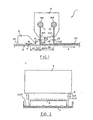
- the coating unit 1 carries, as in the schematic elevation of FIG. 1 shown, different coating materials t1, t2 in two layers on one side of the base paper web 2, while the latter (in the direction of arrow A in FIG. 1 ) is transported.
- the coater (double coater) 1 is provided with a compact feeder (first applicator, second applicator) 4 which discharges the first coating material t1 and forms the first coating material curtain tc1 and at the same time delivers the second coating material t2 and forms the second coating material curtain tc2 therefrom
- Blocking plate (blocking element) 8 which is arranged between the first coating material curtain tc1 and the second coating material curtain tc2, and with an air separation device 6, which is arranged on the transport path of the web 2 above said compact feeder 4 and separates air adhering to the transported web 2.
- the said web 2 is transported at a speed of 100-2000 m / min in the direction of arrow A.
- Said compact feeder 4 has a pair of header tanks 4h1 and 4h2 (header), and the first coating material t1 and the second coating material t2 are pressurized by pumps (not shown) and fed respectively to a collection tank 4h1 and 4h2, respectively.
- the first coating material t1 and the second coating material t2 are then discharged from the collection tanks 4h1 and 4h2 of the compact feeder 4 via the nozzles 4n1 and 4n2 respectively as 1st coating material curtain tc1 and 2nd coating material curtain tc2 in the form of liquid films having thicknesses a1 and a2, respectively For example, 0.3 mm from the top of the web 2 applied.
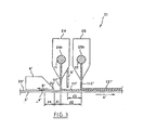
- the first coating material curtain tc1 and the second coating material curtain tc2 have as shown in FIG. 2 , the right side view of the coating system 1 of FIG. 1
- the uncoated excess coating materials t1 and t2 are collected and recovered in a color pan 7 (color pan).
- the film thickness of the first coating material t1 and the second coating material t2 applied to the web 2 using the compact feeder 4 is different depending on the feeding rate and the web speed, but ranges between 2-100 ⁇ m.
- the said blocking plate 8 is a partitioning plate which is installed to prevent the 1st coating material curtain tc1 and the 2nd coating material curtain tc2 from vibrating.
- a stainless steel plate of 5 mm thickness is used for this purpose.
- the gap between the end of this locking plate 8 and the web 2 should be as narrow as possible, but to avoid contact of the web 2, a distance of 5-10 mm is appropriate.
- the installation of the blocking plate 8 thus blocks this air flow and prevents the coating material curtains tc1 and tc2 from vibrating, which enables a satisfactory coating of the web 2.
- the air eliminator 6 is intended to prevent the coating material curtains tc1 with its wind and tc2 are disturbed and an inferior coating is formed.
- This air separation device 6 supplies a high-speed air flow a at a speed of 60-100 m / s by means of a fan (not shown) and via a duct (duct) (not shown). It blows the high velocity air flow a at a speed of 60-100 m / s in the opposite direction (arrow B in Figure 1 [a]) of the transport direction of the web 2 (arrow A in FIG FIG. 1 ) on the intended application surface 2n of the web 2 and removes there adhering air.
- the distance I 4 between the tip 6s of the air separation device 6 and the exit port of the high velocity air flow a is 50-150 mm, the distance between the lower surface of the air separator 6 and the web 2 to 1 mm.
- the high-velocity air flow a causes the first coating material curtain tc1 to vibrate.
- the distance I 4 is too large, a good blocking effect results (sealing), but the web 2 is sucked to the outlet opening of the high-velocity air stream 6.
- the distance I 4 is too small, high production costs, the need for a large mounting space, etc., arise. Disadvantage.
- a distance I 4 of 110-120 mm is required.
- the distance I 1 between the tip 6s of the air separation device 6 and the coating material curtain tc1 is 10 to 50 mm, more preferably 20 to 30 mm.
- the first coating material curtain tc1 comes under the influence of the high-velocity air flow a of the air separation device 6 for swinging, and there is a phenomenon that the first coating material t1 sticks to the air separation device 6.
- a range of 30-100 mm is suitable, more favorably a range of 50-90 mm.
- a distance I 3 between the blocking plate 8 and the second coating material curtain tc2 in the range of 20-80 mm is suitable. This distance I 3 is determined as a function of the distance I 2 between the coating material curtains tc1 and tc2.
- the curtain flow rate was 5-20 l / min per 1 m width of the first coating material curtain tc1 and 5-20 l / min per 1 m width of the second coating material curtain tc2.
- the air separation device 6 because the air separation device 6, the high-speed air flow a at a speed of 60-100 m / s of the transport direction opposite (arrow B in FIG. 1 ) blows onto the intended application surface 2n of the web 2, the air (air) adhering to the web 2 is removed, forming a stable coating without disturbing the coating material curtains tc1 and tc2, as in FIG. 1 shown, enabled.
- first the first coating material t1 is applied by means of the first coating material curtain tc1 and a coating film (1st application layer) t11 of 2-100 ⁇ m the web 2 formed.
- the second coating material t2 is applied, and a coating film (2nd application layer) t21 of 2-100 ⁇ m of the web 2 is formed.
- the blocking plate 8 is disposed between the first coating material curtain tc1 and the second coating material curtain tc2, disturbances due to mutual interference between the first coating material curtain tc1 and the second coating material curtain tc2 are prevented and the first and second coating materials t1 and t2 are properly applied to the intended application surface 2n applied to the web 2.
- the coating film t11 consisting of the first coating material t1 and the coating film t21 consisting of the second coating material t2 do not mix because they are different types of coating material, but dissolve only water vapor on.
- wet-on-wet double coating and then drying are performed on one side of the web 2, followed by a similar wet-on-wet double coating and drying on the other side of the web 2, thus completing the application process is.
- the blocking plate 8 is disposed between the first coating material curtain tc1 and the second coating material curtain tc2, disturbances of the liquid films are prevented by mutual interference between the first coating material curtain tc1 and the second coating material curtain tc2, and the coating materials t1 and t2 are properly applied to the sheet 2 ,
- wet-on-wet double coating can be realized with two separate coating materials of simple construction.
- the coating system 21 (double coating system) of the present invention is shown in a schematic frontal section of FIG. 3 shown.
- the compact feeder 4 of the coater 1 of Embodiment 1 has been replaced with the single feeder (first feeder) 24 having a collection tank 24h and the single feeder (second feeder) 25 having a collection tank 25h.
- the other structure of the coating apparatus 21 is the same as that of the coating apparatus 1 of Example 1, and therefore the symbols of the structural elements corresponding to those of the coating apparatus 1 of Embodiment 1 are simply given a '(dash). For the same reason, a detailed explanation is omitted.
- FIG. 3 also has the same effects as the double coater according to FIG. 1 ,
- the blocking plate 8 or 8 ' is formed as a flat plate.
- the element is not limited to this shape as long as it is interposed between the first coating material curtain and the second coating material curtain and can prevent mutual interference therebetween.
- coating equipment for applying coating material to calendars, catalogs, thermal sheets, pressure-sensitive paper, etc. and coating equipment for applying magnetic material to a page of automatically controlled tickets and others can be cited
Landscapes
- Coating Apparatus (AREA)
- Application Of Or Painting With Fluid Materials (AREA)
- Machines For Manufacturing Corrugated Board In Mechanical Paper-Making Processes (AREA)
- Paper (AREA)
Description
- Die vorliegende Erfindung bezieht sich auf eine Doppelbeschichtungsanlage zum mehrfachen Auftragen von Beschichtungsmaterialien auf Bahnen aus Papier o.ä.
- Gewöhnlich ist die Oberfläche von Kalendern und Katalogen optisch glänzend, was daran liegt, daß auf ihr Beschichtungsmaterialien aufgetragen sind.
- In gleicher Weise werden Beschichtungsmaterialien auf Thermoblätter und druckempfindliches (kohlenstofffreies) Papier aufgetragen, wodurch diese die Funktion von Drucken und Kopien übernehmen. Auch auf eine Seite von automatisch kontrollierten Tickets wird magnetisches Material aufgetragen, um sie magnetisch registrieren zu können.
- Maschinen, die ein solches Auftragen von Beschichtungsmaterial ausführen, werden allgemein als Beschichter bezeichnet und sind mit Strecken (lines) versehen, die den Prozeß des Auftragens und den des Trocknens beinhalten.
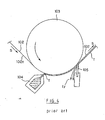
- Wie in dem schematischen Frontalschnitt von
Figur 4 dargestellt, läuft die von einem (hier nicht gezeigten) Rollapparat (winder) abgegebene Rohpapierbahn 102 um eine rotierende Stützwalze 103 und wird in Pfeilrichtung s transportiert. - Das Beschichtungsmaterial wird aus dem Speiser 104 (head) in Richtung der Auftragfläche 102n der Bahn 102 ausgebracht und aufgetragen. Das aufwärts angeordnete Messer 105 streift das aufgetragene Beschichtungsmaterial t dann im vorgeschriebenen Umfang ab (die Pfeile ty in
Figur 4 ). - Nun wird die einseitig mit dem Beschichtungsmaterial t versehene Bahn 102 zu einem (hier nicht gezeigten) Trockner transportiert und die Trocknung des aufgetragenen Beschichtungsmaterials t vollzogen. Im Anschluß wird die entgegengesetzten Seite der mit dem Beschichtungsmaterial t versehenen Seite der Bahn 102 als neue Auftragfläche in gleicher Weise mit dem Beschichtungsmaterial t beschichtet und getrocknet.
- Dann wird der genannte Prozeß wiederholt, und die beiden mit dem Beschichtungsmaterial t versehenen Seiten der Bahn 102 werden mit einem anderen Beschichtungsmaterial mehrfach beschichtet.
- Ein Apparat zur Wet-on-Wet Doppelbeschichtung mittels zweier Auftragsaggregate in Form von Vorhangbeschichtern ist aus der
US-A 2002/066404 bekannt. Der Beschichtungsmaterialvorhang des ersten Auftragsaggregates befindet sich dabei in einem bestimmten Abstand zum Vorhang des zweiten Auftragsaggregates.
Ein Einfluss von eingetragener Luft kann zur Beeinträchtigung der beiden abgegebenen Vorhänge führen.
In derUS-A 5,773,093 und derJP-A-05 004441 - Außerdem existiert nach die
JP 4-131700 (1992 - Bei den o.g. Beschichter gemäß
Figur 4 wäre eine sogenannte Wet-on-Wet-Doppelbeschichtung schwierig, bei der nach dem Auftragen des Beschichtungsmaterials t auf die Bahn 102 im feuchten Zustand, d.h. ohne Trocknung, nochmals eine Beschichtung durchgeführt wird. Nach dem Auftragen des Beschichtungsmaterials t auf die Bahn 102 erfolgt dabei nämlich ein Post-Metering, ein Abschaben, oder ein Impact-Coating, ein Preßauftragen von Beschichtungsmaterial t auf die Bahn 102. - Bei der Realisierung einer Wet-on-Wet-Doppelbeschichtung stellen sich folgende Probleme:
- Der Realisierung einer Wet-on-Wet-Doppelbeschichtung steht entgegen, daß sich das Beschichtungsmaterial der auf den Untergrund aufgetragenen Grundbeschichtung mit dem der darüber aufgetragenen Deckbeschichtung mischt, daß Air-Turn-Vorrichtungen erforderlich sind, damit die Beschichtungsfläche der Bahn 102 keine Transportrollen berührt, und daß es bei einer Wet-on-Wet-Doppelbeschichtung aufgrund der Geräteanordnung einen komplizierten Bahnlauf (web path) und damit häufige Papierrisse gibt.
- Der vorliegenden Erfindung liegt die Aufgabe zugrunde, eine Doppelbeschichtungsanlage bereitzustellen, mit der sich die Wet-on-Wet-Doppelbeschichtung einer Bahn einfach realisieren läßt.
- Die Aufgabe der Erfindung wird wie folgt gelöst:
Die sich auf Anspruch 1 der vorliegenden Erfindung beziehende Doppelbeschichtungsanlage, welche das o.a. Ziel erreichen soll, trägt Beschichtungsmaterial in zwei Schichten auf eine Bahn auf, während letztere transportiert wird, und ist dadurch gekennzeichnet, daß sie ausgestattet ist mit einem ersten Auftraggerät, welches das erste Beschichtungsmaterial von oben auf die Bahn gerichtet abgibt, einen ersten Beschichtungsmaterialvorhang bildet, das erste Beschichtungsmaterial auf die besagte Bahn aufträgt und eine erste Auftragschicht formt, mit einem zweiten Auftraggerät, welches am Transportweg der Bahn in einem bestimmten Abstand unterhalb des besagten ersten Auftraggeräts angeordnet ist, das zweite Beschichtungsmaterial von oben auf die Bahn gerichtet abgibt, einen zweiten Beschichtungsmaterialvorhang bildet, das zweite Beschichtungsmaterial auf die erste Auftragschicht der besagten Bahn aufträgt und eine zweite Auftragschicht formt, sowie mit einem Sperrelement, das den besagten ersten Beschichtungsmaterialvorhang und den besagten zweiten Beschichtungsmaterialvorhang räumlich voneinander trennt und zwischen dem besagten ersten Beschichtungsmaterialvorhang und dem besagten zweiten Beschichtungsmaterialvorhang angeordnet ist, und die mittels des besagten Sperrelements Störungen durch wechselseitige Beeinflussungen zwischen dem besagten erste Beschichtungsmaterialvorhang und dem besagten zweiten Beschichtungsmaterialvorhang vorbeugt und so das erste und das zweite Beschichtungsmaterial auf die besagte Bahn aufträgt. - Die erfindungsgemäße Vorrichtung ist außerdem ausgestattet ist mit einer Luftabscheidvorrichtung, die am Transportweg der Bahn oberhalb des besagten ersten Bes chichtungsmaterialvorhangs angeordnet ist und einen Hochgeschwindigkeitsluftstrom entgegen der Transportrichtung der besagten Bahn auf die vorgesehene Auftragfläche der transportierten Bahn bläst, und an der vorgesehenen Auftragfläche der besagten transportierten Bahn haftende Luft durch den Hochgeschwindigkeitsluftstrom der besagten Luftabscheidvorrichtung weggeblasen und damit Störungen des besagten ersten Beschichtungsmaterialvorhangs und des besagten zweiten Beschichtungsmaterialvorhangs vorgebeugt wird.
- Die sich auf Anspruch 2 der vorliegenden Erfindung beziehende Doppelbeschichtungsanlage ist eine Doppelbeschichtungsanlage nach Anspruch 1 und dadurch gekennzeichnet, daß sich die Spitze der besagten Luftabscheidvorrichtung am Transportweg der Bahn unten befindet und die Austrittsöffnung des besagten Hochgeschwindigkeitsluftstroms am Transportweg der Bahn oberhalb der besagten Spitze angeordnet ist sowie der Abstand zwischen der besagten Spitze und der Austrittsöffnung des besagten Hochgeschwindigkeitsluftstroms 50-150 mm beträgt.
- Die sich auf Anspruch 3 der vorliegenden Erfindung beziehende Doppelbeschichtungsanlage 6 gekennzeichnet, daß der Abstand zwischen der Spitze der besagten Luftabscheidvorrichtung und dem besagten 1. Beschichtungsmaterialvorhang 10-50 mm beträgt.
- Die sich auf Anspruch 4 der vorliegenden Erfindung beziehende Doppelbeschichtungsanlage dadurch gekennzeichnet, daß der Abstand zwischen dem besagten ersten Beschichtungsmaterialvorhang und dem besagten zweiten Beschichtungsmaterialvorhang 30-100 mm beträgt.
- Die sich auf Anspruch 5 der vorliegenden Erfindung beziehende Doppelbeschichtungsanlage ist dadurch gekennzeichnet, daß der Abstand zwischen dem besagten Sperrelement und dem besagten zweiten Beschichtungsmaterialvorhang 20-80 mm beträgt.
- Weil bei der sich auf Anspruch 1 der vorliegenden Erfindung beziehenden Doppelbeschichtungsanlage mittels eines Sperrelements Störungen durch wechselseitige Beeinflussungen zwischen dem ersten Beschichtungsmaterialvorhang und dem zweiten Beschichtungsmaterialvorhang vorgebeugt wird und das erste und das zweite Beschichtungsmaterial so ordnungsgemäß auf die Bahn gelangen, kann eine Wet-on-Wet-Doppelbeschichtung ohne Beschichtungsstörungen realisiert werden.
- Außerdem wird an der vorgesehenen Auftragfläche der transportierten Bahn haftende Luft durch den Hochgeschwindigkeitsluftstrom einer Luftabscheidvorrichtung weggeblasen Dadurch kann Störungen des ersten Beschichtungsmaterialvorhangs und des zweiten Beschichtungsmaterialvorhangs vorgebeugt und eine sehr zuverlässige Wet-on-Wet-Doppelbeschichtung realisiert werden.
- Weil bei der sich auf Anspruch 2 der vorliegenden Erfindung beziehenden Doppelbeschichtungsanlage die Spitze der Luftabscheidvorrichtung sich am Transportweg der Bahn unten befindet und die Austrittsöffnung des Hochgeschwindigkeitsluftstroms am Transportweg der Bahn oberhalb der Spitze angeordnet ist sowie der Abstand zwischen der Spitze und der Austrittsöffnung des Hochgeschwindigkeitsluftstroms 50-150 mm beträgt, kommt es nicht zu einer Beeinflussung des ersten Beschichtungsmaterialvorhangs durch den Hochgeschwindigkeitsluftstrom der Luftabscheidvorrichtung, was Störungen des ersten Beschichtungsmaterialvorhangs vorbeugt und einen befriedigenden Beschichtungsvorgang ermöglicht.
- Weil bei der sich auf Anspruch 3 der vorliegenden Erfindung beziehenden Doppelbeschichtungsanlage der Abstand zwischen der Spitze der Luftabscheidvorrichtung und dem ersten Beschichtungsmaterialvorhang 10-50 mm beträgt, kommt es nicht zu einer Beeinflussung des ersten Beschichtungsmaterialvorhangs durch den Hochgeschwindigkeitsluftstrom der Luftabscheidvorrichtung oder zum Anhaften von Luft auf der Bahn, was einen noch zuverlässigeren Beschichtungsvorgang ermöglicht.
- Weil bei der sich auf Anspruch 4 der vorliegenden Erfindung beziehenden Doppelbeschichtungsanlage der Abstand zwischen dem ersten Beschichtungsmaterialvorhang und dem zweiten Beschichtungsmaterialvorhang 30-100 mm beträgt, lagert sich keine Luft auf der Bahn ab, was einen befriedigenden Beschichtungsvorgang ermöglicht.
- Weil bei der sich auf Anspruch 5 der vorliegenden Erfindung beziehenden Doppelbeschichtungsanlage der Abstand zwischen dem Sperrelement und dem zweiten Beschichtungsmaterialvorhang 20-80 mm beträgt, kommt es nicht zum Anhaften von Luft auf der Bahn oder zum Festkleben des ersten und zweiten Beschichtungsmaterialvorhangs am Sperrelement, was einen stabilen und zuverlässigen Beschichtungsvorgang ermöglicht.
- Es zeigen:
- Figur 1:
- Schematische Darstellung des Frontalschnitts der Beschichtungsanlage, Beispiel 1
- Figur 2:
- Schematische Darstellung der rechten Seitenansicht der Beschichtungsanlage von
Figur 1 - Figur 3:
- Schematische Darstellung des Frontalschnitts einer Beschichtungsanlage, Beispiel 2
- Es folgt eine Erläuterung von Ausführungsformen der vorliegenden Erfindung mit Verweisen auf die beigefügten Abbildungen.
- Die Beschichtungsanlage 1 trägt, wie in dem schematischen Aufriß von
Figur 1 gezeigt, unterschiedliche Beschichtungsmaterialien t1, t2 in zwei Schichten auf eine Seite der Rohpapierbahn 2 auf, während letztere (in Pfeilrichtung A inFigur 1 ) transportiert wird. - Die Beschichtungsanlage (Doppelbeschichtungsanlage) 1 ist ausgestattet mit einem Kompaktspeiser (erstes Auftraggerät, zweites Auftraggerät) 4, der das erste Beschichtungsmaterial t1 abgibt und daraus den ersten Beschichtungsmaterialvorhang tc1 bildet und gleichzeitig das zweite Beschichtungsmaterial t2 abgibt und daraus den zweiten Beschichtungsmaterialvorhang tc2 bildet, mit einer Sperrplatte (Sperrelement) 8, das zwischen dem ersten Beschichtungsmaterialvorhang tc1 und dem zweiten Beschichtungsmaterialvorhang tc2 angeordnet ist, sowie mit einer Luftabscheidvorrichtung 6, die am Transportweg der Bahn 2 oberhalb des besagten Kompaktspeisers 4 angeordnet ist und an der transportierten Bahn 2 haftende Luft abscheidet.
- Die besagte Bahn 2 wird mit einer Geschwindigkeit von 100-2000 m/min in Pfeilrichtung A transportiert.
- Der besagte Kompaktspeiser 4 besitzt ein Paar Sammeltanks 4h1 und 4h2 (header), und das erste Beschichtungsmaterial t1 sowie das zweite Beschichtungsmaterial t2 werden durch (hier nicht gezeigte) Pumpen unter einen bestimmten Druck gesetzt und jeweils in einen Sammeltank 4h1 bzw. 4h2 eingespeist.
- Das erste Beschichtungsmaterial t1 und das zweite Beschichtungsmaterial t2 werden dann von den Sammeltanks 4h1 bzw. 4h2 des Kompaktspeisers 4 über die Düsen 4n1 bzw. 4n2 als 1. Beschichtungsmaterialvorhang tc1 bzw. 2. Beschichtungsmaterialvorhang tc2 in Form von Flüssigkeitsfilmen mit Dicken a1 bzw. a2 von beispielsweise 0,3 mm von oben auf die Bahn 2 ausgebracht.
- Damit das erste Beschichtungsmaterial t1 und das zweite Beschichtungsmaterial t2 ordentlich auf die Bahn 2 aufgetragen werden, haben der erste Beschichtungsmaterialvorhang tc1 und der zweite Beschichtungsmaterialvorhang tc2, wie in
Figur 2 , der rechten Seitenansicht der Beschichtungsanlage 1 vonFigur 1 , gezeigt, eine größere Breite als die Bahn 2. Die nicht aufgetragenen, überschüssigen Beschichtungsmaterialien t1 und t2 werden in einer Farbwanne 7 (color pan) aufgefangen und zurückgewonnen. - Die Filmdicke des auf die Bahn 2 unter Verwendung des Kompaktspeisers 4 aufgetragenen ersten Beschichtungsmaterials t1 und zweiten Beschichtungsmaterials t2 ist je nach Zufuhrrate und Bahngeschwindigkeit unterschiedlich, bewegt sich aber zwischen 2-100 µm.
- Bei der besagten Sperrplatte 8 handelt es sich um eine Trenntafel, die installiert wird, um ein Schwingen des 1. Beschichtungsmaterialvorhangs tc1 und des 2. Beschichtungsmaterialvorhangs tc2 zu verhindern. Beispielsweise wird dafür eine rostfreie Stahlplatte von 5 mm Dicke eingesetzt.
- Der Spalt zwischen dem Ende dieser Sperrplatte 8 und der Bahn 2 sollte möglichst schmal sein, um aber eine Berührung der Bahn 2 zu vermeiden, ist ein Abstand von 5-10 mm angemessen.
- Wenn diese Sperrplatte 8 nicht installiert ist, wird entsprechend dem Verhalten der Beschichtungsmaterialvorhänge tc1 und tc2 aufgrund der Viskosität Luft angezogen, deren Strömung zu wechselseitigen Beeinflussungen zwischen den Beschichtungsmaterialvorhängen tc1 und tc2 führt und bei ihnen ein Schwingen hervorruft.
- Durch die Installation der Sperrplatte 8 wird diese Luftströmung folglich blockiert und ein Schwingen der Beschichtungsmaterialvorhänge tc1 und tc2 verhindert, was eine befriedigende Beschichtung der Bahn 2 ermöglicht.
- Wenn die Bahn 2 mit einer Geschwindigkeit von etwa 300 m/min oder mehr transportiert wird, kommt es aufgrund ihrer Viskosität zur Anhaftung von Luft (air) an der Oberfläche der Bahn 2. Die Luftabscheidvorrichtung 6 soll mit ihrem Wind verhindern, daß die Beschichtungsmaterialvorhänge tc1 und tc2 gestört werden und eine minderwertige Beschichtung entsteht.
- Diese Luftabscheidvorrichtung 6 liefert mittels eines (hier nicht gezeigten) Gebläses (fan) und über eine (hier nicht gezeigte) Rohrleitung (duct) einen Hochgeschwindigkeitsluftstrom a mit einer Geschwindigkeit von 60-100 m/s. Sie bläst den Hochgeschwindigkeitsluftstrom a mit einer Geschwindigkeit von 60-100 m/s in die Gegenrichtung (Pfeil B in Abbildung 1[a]) der Transportrichtung der Bahn 2 (Pfeil A in
Figur 1 ) auf die vorgesehene Auftragfläche 2n der Bahn 2 und entfernt dort haftende Luft. - Der Abstand I 4 zwischen der Spitze 6s der Luftabscheidvorrichtung 6 und der Austrittsöffnung des Hochgeschwindigkeitsluftstroms a ist auf 50-150 mm festgelegt, der Abstand zwischen der unteren Fläche der Luftabscheidvorrichtung 6 und der Bahn 2 auf 1 mm.
- Bei zu geringem Abstand I 4 bringt der Hochgeschwindigkeitsluftstrom a den 1. Beschichtungsmaterialvorhang tc1 zum Schwingen. Ist der Abstand I 4 demgegenüber zu groß, ergibt sich zwar eine gute Sperrwirkung (sealing), aber die Bahn 2 wird an die Austrittsöffnung des Hochgeschwindigkeitsluftstroms 6 gesaugt. Wird sie in diesem Zustand transportiert, bekommt ihre Oberfläche Kratzer. Bei zu geringem Abstand I 4 entstehen hohe Fertigungskosten, die Notwendigkeit eines großen Aufbauraums u.a. Nachteile.
- Verwendet man einen schnelleren Hochgeschwindigkeitsluftstrom a, beispielsweise einen von 80-100 m/s, ist ein Abstand I 4 von 110-120 mm erforderlich.
- Aus all dem ergibt sich, daß ein Abstand I 4 von 110-120 mm am günstigsten ist.
- Mit einer vorteilhaften Festlegung des Abstands I 4 zwischen der Spitze 6s der Luftabscheidvorrichtung 6 und der Austrittsöffnung des Hochgeschwindigkeitsluftstroms a kann u.a. eine Beeinflussung des ersten Beschichtungsmaterialvorhangs tc1 durch den Hochgeschwindigkeitsluftstrom a vermieden werden, was eine zufriedenstellende Beschichtung mittels des ersten Beschichtungsmaterialvorhangs tc1 ermöglicht.
- Bei dem beschriebenen Aufbau ist nach Ansicht der Erfinder hinsichtlich des Abstands I 1 zwischen der Spitze 6s der Luftabscheidvorrichtung 6 und dem Beschichtungsmaterialvorhang tc1 ein Bereich von 10-50 mm geeignet, noch günstiger ist ein Bereich von 20-30 mm.
- Bei einem zu geringen Abstand I 1 kommt der erste Beschichtungs - materialvorhang tc1 unter der Einwirkung des Hochgeschwindigkeitsluftstroms a der Luftabscheidvorrichtung 6 zum Schwingen, und es tritt das Phänomen auf, daß das erste Beschichtungsmaterial t1 an der Luftabscheidvorrichtung 6 kleben bleibt.
- Ist der Abstand I 1 demgegenüber zu groß, kommt es nach dem Abscheiden der Luft von der Bahn 2 durch die Luftabscheidvorrichtung 6 aufgrund des Transports erneut zum Anhaften von Luft an der Bahn 2, was den ersten Beschichtungsmaterialvorhang tc1 zum Schwingen bringt.
- Hinsichtlich des Abstands I 2 zwischen den Beschichtungsmaterialvorhängen tc1 und tc2 ist ein Bereich von 30-100 mm geeignet, noch günstiger ist ein Bereich von 50-90 mm.
- Bei einem zu geringen Abstand I 2 berühren die Beschichtungsmaterialvorhänge tc1 und tc2 die Sperrplatte 8. Ist der Abstand I 2 demgegenüber zu groß, kommt es erneut zum Anhaften von Luft an der Bahn 2, was den zweiten Beschichtungsmaterialvorhang tc2 zum Schwingen bringt.
- Was die Position der zwischen den Beschichtungsmaterialvorhängen tc1 und tc2 angeordneten Sperrplatte 8 anbetrifft, so ist die Mitte zwischen den beiden Beschichtungsmaterialvorhängen tc1 und tc2 kaum vorteilhaft. Geeignet ist ein Abstand I 3 zwischen der Sperrplatte 8 und dem zweiten Beschichtungsmaterialvorhang tc2 im Bereich von 20-80 mm. Dieser Abstand I 3 wird in Abhängigkeit vom Abstand I 2 zwischen den Beschichtungsmaterialvorhängen tc1 und tc2 festgelegt.
- Bei Tests auf der Grundlage dieser Daten, z.B. mit einem Abstand I 1 von 25-30 mm, einem Abstand I 2 von 90 mm und einem Abstand I 3 von 65-70 mm, war bis zu einer Beschichtungsgeschwindigkeit der Bahn 2 von 800 m/min eine stabile Beschichtung gewährleistet.
- Die Vorhangsdurchflußmenge betrug dabei 5-20 l/min pro 1 m Breite des ersten Beschichtungsmaterialvorhangs tc1 und 5-20 l/min pro 1 m Breite des zweiten Beschichtungsmaterialvorhangs tc2.
- Wird unter diesen Bedingungen der Abstand I 3 zwischen der Sperrplatte 8 und dem zweiten Beschichtungsmaterialvorhang tc2 verkürzt, beginnt der zweite Beschichtungsmaterialvorhang tc2 zu schwingen, und die Beschichtung wird instabil. Setzt sich dies fort, werden die Schwingungen größer, und es entstehen Beschichtungsfehler.
- Im folgenden wird der Auftragprozeß auf die Bahn 2 mittels der Beschichtungsanlage 1 erläutert.
- Wenn die Bahn 2, wie in
Figur 1 dargestellt, in Pfeilrichtung A transportiert wird und ihre Geschwindigkeit etwa 300 m/min oder mehr beträgt, kommt es aufgrund der ihrer Viskosität zur Anhaftung von Luft an der Oberfläche der Bahn 2. Die Beschichtungsmaterialvorhänge tc1 und tc2 werden dadurch gestört und es entsteht eine fehlerhafte Beschichtung. - Weil aber die Luftabscheidvorrichtung 6 den Hochgeschwindigkeitsluftstrom a mit einer Geschwindigkeit von 60-100 m/s der Transportrichtung entgegengesetzt (Pfeil B in
Figur 1 ) auf die vorgesehene Auftragfläche 2n der Bahn 2 bläst, wird die an der Bahn 2 haftende Luft (air) entfernt, was eine stabile Beschichtung ohne Störung der Beschichtungsmaterialvorhänge tc1 und tc2, wie inFigur 1 gezeigt, ermöglicht. - Auf die vorgesehene Auftragfläche 2n der Bahn 2, die unter dieser Luftabscheidvorrichtung 6 hindurchgegangen ist und von der anhaftende Luft entfernt wurde, wird zunächst mittels des ersten Beschichtungsmaterialvorhangs tc1 das erste Beschichtungsmaterial t1 aufgetragen und ein Beschichtungsfilm (1. Auftragschicht) t11 von 2-100 µm der Bahn 2 gebildet.
- Danach wird auf den Beschichtungsfilm t11 der Bahn 2 mittels des zweiten Beschichtungsmaterialvorhangs tc2 das zweite Beschichtungsmaterial t2 aufgetragen und ein Beschichtungsfilm (2. Auftragschicht) t21 von 2-100 µm der Bahn 2 gebildet.
- Weil zwischen dem ersten Beschichtungsmaterialvor hang tc1 und dem zweiten Beschichtungsmaterialvorhang tc2 die Sperrplatte 8 angebracht ist, wird Störungen durch wechselseitige Beeinflussungen zwischen dem ersten Beschichtungsmaterialvorhang tc1 und dem zweiten Beschichtungsmaterialvorhang tc2 vorgebeugt und das erste und das zweite Beschichtungsmaterial t1 und t2 ordnungsgemäß auf die vorgesehene Auftragfläche 2n der Bahn 2 aufgetragen.
- Bei der beschriebenen Wet-on-Wet-Doppelbeschichtung kommt es nicht zu einer Vermischung des aus dem ersten Beschichtungsmaterial t1 bestehenden Beschichtungsfilms t11 und des aus dem zweiten Beschichtungsmaterial t2 bestehenden Beschichtungsfilms t21, weil es sich um unterschiedliche Arten von Beschichtungsmaterial handelt, sondern es löst sich lediglich Wasserdampf auf.
- Bei diesem Prozeß wird auf einer Seite der Bahn 2 eine Wet-on-Wet-Doppelbeschichtung und anschließend eine Trocknung durchgeführt, gefolgt von einer gleichartigen Wet-on-Wet-Doppelbeschichtung und Trocknung auf der anderen Seite der Bahn 2, womit dann der Auftragvorgang abgeschlossen ist.
- Durch den beschriebenen Aufbau wird eine Wet-on-Wet-Doppelbeschichtung der Bahn 2 mittels einer Beschichtungsanlage 1 möglich.
- Weil die dafür bislang erforderlichen zwei Beschichter hier zu einer Beschichtungsanlage 1 zusammengefaßt sind, werden z.B. Teile gemeinsam genutzt. Setzt man die Kosten einer Beschichtungsmaschine gleich 100, so kommt man bei den bislang erforderlichen zwei Maschinen auf eine Summe von 200. Mit der Beschichtungsanlage 1 nach der vorliegenden Erfindung lassen sich die Kosten demgegenüber auf etwa 120 senken.
- Da zwei Beschichter zu einer Beschichtungsanlage 1 zusammengefaßt sind, ergibt sich ein kompakter Aufbau, und der Platzbedarf ist im Vergleich zu früher gering.
- Weil zwischen dem ersten Besc hichtungsmaterialvorhang tc1 und dem zweiten Beschichtungsmaterialvorhang tc2 die Sperrplatte 8 angebracht ist, wird Störungen der Flüssigkeitsfilme durch wechselseitige Beeinflussungen zwischen dem ersten Beschichtungsmaterialvorhang tc1 und dem zweiten Beschichtungsmaterialvorhang tc2 vorgebeugt, und die Beschichtungsmaterialien t1 und t2 werden ordnungsgemäß auf die Bahn 2 aufgetragen.
- Nach der vorliegenden Erfindung läßt sich folglich eine Wet-on-Wet-Doppelbeschichtung mit zwei getrennten Beschichtungsmaterialien mit einfachem Aufbau realisieren.
- Die Beschichtungsanlage 21 (Doppelbeschichtungsanlage) der vorliegenden Erfindung, ist in schematischem Frontalschnitt von
Figur 3 dargestellt. - Bei der Beschichtungsanlage 21 von Ausführungsbeispiel 2 ist der Kompaktspeiser 4 der Beschichtungsanlage 1 von Ausführungsbeispiel 1 durch den Einzelspeiser (erstes Auftraggerät) 24 mit einem Sammeltank 24h und den Einzelspeiser (zweites Auftraggerät) 25 mit einem Sammeltank 25h ersetzt worden.
- Der sonstige Aufbau der Beschichtungsanlage 21 stimmt mit dem der Beschichtungsanlage 1 von Beispiel 1 überein, weshalb die Symbole der Strukturelemente, die denen der Beschichtungsanlage 1 von Ausführungsbeispiel 1 entsprechen, einfach mit einem ' (Strich) versehen sind. Aus dem gleichen Grund wird auf eine detaillierte Erläuterung verzichtet.
- Der Aufbau des in
Figur 3 gezeigten Doppelbeschichters hat auch die gleichen Effekte wie der Doppelbeschichter gemäßFigur 1 . - In den beschriebenen Beispielen 1 und 2 ist die Sperrplatte 8 bzw. 8' als ebene Tafel ausgebildet. Das Element ist aber nicht auf diese Form beschränkt, solange es zwischen dem ersten Beschichtungsmaterialvorhang und dem zweiten Beschichtungsmaterialvorhang angeordnet ist und wechselseitigen Beeinflussungen zwischen ihnen vorbeugen kann.
- Als Nutzungsbeispiele der vorliegenden Erfindung lassen sich Beschichtungsanlagen zum Auftragen von Beschichtungsmaterial auf Kalender, Kataloge, Thermoblätter, druckempfindliches Papier usw. anführen, weiterhin Beschichtungsanlagen zum Auftragen magnetischen Materials auf eine Seite von automatisch kontrollierten Tickets u.a.
-
- 1, 21
- Beschichtungsanlage (Doppelbeschichtungsanlage)
- 2, 2'
- Bahn (web)
- 4
- Kompaktspeiser (erstes Auftraggerät, zweites Auftraggerät)
- 6, 6'
- Luftabscheidvorrichtung (air cut device)
- 6s, 6s'
- Spitze der Luftabscheidvorrichtung
- 7
- Farbwanne
- 8
- Sperrplatte (Sperrelement)
- 24
- Einzelspeiser (erstes Auftraggerät)
- 25
- Einzelspeiser (zweites Auftraggerät)
- a
- Hochgeschwindigkeitsluftstrom
- t1
- Erstes Beschichtungsmaterial
- t11, t11'
- Beschichtungsfilm (erste Auftragschicht)
- tc1, tc1'
- Erster Beschichtungsmaterialvorhang
- t2
- Zweites Beschichtungsmaterial
- t21, t21'
- Beschichtungsfilm (zweite Auftragschicht)
- tc2, tc2'
- Zweiter Beschichtungsmaterialvorhang
- 2n, 2n'
- vorgesehene Auftragfläche
Claims (5)
- Doppelbeschichtungsanlage, die Beschichtungsmaterial in zwei Schichten auf eine laufende Bahn aufträgt,
dadurch gekennzeichnet, dass sie ausgestattet ist mita) einem ersten Auftragsgerät (24) bzw. einem Kompaktspeiser (4), welches das erste Beschichtungsmaterial (t1) von oben auf die Bahn (2, 2') gerichtet abgibt und einen ersten Beschichtungsmaterialvorhang (tc1) bildet, wobei das erste Beschichtungsmaterial (t1) auf der besagten Bahn auftrifft und eine erste Auftragschicht (t21) formt,
mitb) einem zweiten Auftragsgerät (25) bzw. einem Kompaktspeiser (4), welches am Transportweg der Bahn (2) in einem bestimmten Abstand nach dem besagten ersten Auftraggerät (24) angeordnet ist und das zweite Beschichtungs-material (t2) von oben auf die Bahn (2) gerichtet abgegeben und einen zweiten Beschichtungsmaterialvorhang (tc2) bildet, wobei das zweite Beschichtungsmaterial (t2) auf die erste Auftragschicht (t11) auftrifft und eine zweite Auftragschicht (t21) formt,
mitc) einem Sperrelement (8), das den besagten ersten Beschichtungsmaterialvorhang (tc1) und den besagten zweiten Beschichtungsmaterialvorhang (tc2) räumlich voneinander trennt und zwischen dem besagten ersten Beschichtungsmaterialvorhang (tc1) und dem besagten zweiten Beschichtungsmaterialvorhang (tc2) angeordnet ist, wodurch Störungen infolge wechselseitiger Beeinflussungen zwischen dem besagten ersten Beschichtungsmaterialvorhang (tc1) und dem besagten zweiten Beschichtungsmaterialvorhang (tc2) vermeidbar sind.und mit d) einer Luftabscheidvorrichtung (6), die am Transportweg der Bahn (2) vor dem besagten ersten Beschichtungsmaterialvorhang (tc1) angeordnet ist und einen Hochgeschwindigkeitsluftstrom entgegen der Transportrichtung der besagten Bahn (2) auf die vorgesehene Auftragfläche (2n) der transportierten Bahn (2) bläst, und dadurch an der vorgesehenen Auftragfläche (2n) der besagten transportierten Bahn (2) haftende Luft weggeblasen und damit Störungen des besagten ersten Beschichtungsmaterialvorhangs (tc1) und des besagten zweiten Beschichtungsmaterialvorhangs (tc2) vermeidbar, zumindest aber minimierbar sind. - Doppelbeschichtungsanlage nach Anspruch 1,
dadurch gekennzeichnet, dass
sich die Spitze (6s) der besagten Luftabscheidvorrichtung (6) am Transportweg der Bahn (2) unten befindet und die Austrittsöffnung des besagten Hochgeschwindigkeitsluftstroms am Transportweg der Bahn (2) oberhalb der besagten Spitze (6s) angeordnet ist sowie der Abstand zwischen der besagten Spitze (6s) und der Austrittsöffnung des besagten Hochgeschwindigkeitsluftstroms 50-150 mm beträgt. - Doppelbeschichtungsanlage nach Anspruch 2,
dadurch gekennzeichnet, dass
der Abstand zwischen der Spitze (6s) der besagten Luftabscheidvorrichtung und dem besagten ersten Beschichtungsmaterialvorhang (t11) 10-50 mm beträgt. - Doppelbeschichtungsanlage nach einem der Ansprüche 1 bis 3,
dadurch gekennzeichnet, dass
der Abstand zwischen dem besagten ersten Beschichtungsmaterialvorhang (t11) und dem besagten zweiten Beschichtungs - materialvorhang (t21) 30-100 mm beträgt. - Doppelbeschichtungsanlage nach einem der Ansprüche 1 bis 4,
dadurch gekennzeichnet, dass
der Abstand zwischen dem besagten Sperrelement (8) und dem besagten zweiten Beschichtungsmaterialvorhang (t21) 20-80 mm beträgt.
Applications Claiming Priority (2)
| Application Number | Priority Date | Filing Date | Title |
|---|---|---|---|
| JP2003401519 | 2003-12-01 | ||
| JP2003401519A JP2005161153A (ja) | 2003-12-01 | 2003-12-01 | ダブル塗工装置 |
Publications (2)
| Publication Number | Publication Date |
|---|---|
| EP1538262A1 EP1538262A1 (de) | 2005-06-08 |
| EP1538262B1 true EP1538262B1 (de) | 2009-04-22 |
Family
ID=34463924
Family Applications (1)
| Application Number | Title | Priority Date | Filing Date |
|---|---|---|---|
| EP04028315A Expired - Lifetime EP1538262B1 (de) | 2003-12-01 | 2004-11-30 | Doppelbeschichtungsanlage |
Country Status (4)
| Country | Link |
|---|---|
| EP (1) | EP1538262B1 (de) |
| JP (1) | JP2005161153A (de) |
| AT (1) | ATE429541T1 (de) |
| DE (1) | DE502004009387D1 (de) |
Families Citing this family (14)
| Publication number | Priority date | Publication date | Assignee | Title |
|---|---|---|---|---|
| DE102004062119A1 (de) * | 2004-12-23 | 2006-07-13 | Voith Paper Patent Gmbh | Verfahren zum direkten Aufbringen einer Mehrfachschicht auf eine laufende Papier-, Karton- oder andere Faserstoffbahn |
| FI117344B (fi) * | 2004-12-31 | 2006-09-15 | M Real Oyj | Päällystetty paperituote sekä menetelmä ja laitteisto sen valmistamiseksi |
| JP4683968B2 (ja) | 2005-03-11 | 2011-05-18 | ボイス ペ−パ− パテント ゲ−エムベ−ハ− | カーテン式コータ |
| DE102005036667A1 (de) * | 2005-08-04 | 2007-02-08 | Voith Patent Gmbh | Auftragsverfahren |
| US20080166530A1 (en) * | 2006-12-27 | 2008-07-10 | Fujifilm Corporation | Multi-layer coating method, and planographic printing plate and manufacturing method thereof |
| JP5239011B2 (ja) * | 2008-01-22 | 2013-07-17 | ボイス パテント ゲーエムベーハー | タンデム型カーテンコータのエアーカット装置 |
| DE102008041419A1 (de) | 2008-08-21 | 2010-02-25 | Voith Patent Gmbh | Vorrichtung zur Erzeugung von beschichteten Papier-, Karton- oder anderen Faserstoffbahnen mit zumindest einer thermosensitiven Schicht und Verfahren zum Betreiben einer derartigen Vorrichtung |
| DE102008041422A1 (de) * | 2008-08-21 | 2010-02-25 | Voith Patent Gmbh | Vorrichtung zur Erzeugung von beschichteten Papier-, Karton- oder anderen Faserstoffbahnen mit mindestens einer thermosensitiven Schicht und Verfahren zum Betreiben einer derartigen Vorrichtung |
| DE102009046095B4 (de) * | 2009-10-28 | 2016-07-28 | Valmet Technologies, Inc. | Anordnung zur Kontrolle von den in der Florstreichvorrichtung mit der Bahn geführten Luftströmungen |
| EP2353736A1 (de) | 2010-01-29 | 2011-08-10 | 3M Innovative Properties Company | Kontinuierliches Verfahren zur Bildung einer mehrschichtigen Folie und mit dem Verfahren hergestellte mehrschichtige Folie |
| CN102221784B (zh) * | 2010-04-19 | 2013-07-24 | 北京京东方光电科技有限公司 | 胶涂覆设备及胶涂覆方法 |
| EP2551024B1 (de) | 2011-07-29 | 2017-03-22 | 3M Innovative Properties Co. | Mehrschichtige Folie mit mindestens einer dünnen Schicht und kontinuierliches Verfahren zur Bildung einer derartigen Folie |
| DE102011085432A1 (de) * | 2011-10-28 | 2013-05-02 | Metso Paper, Inc. | Verfahren und Vorrichtung zum Beschichten einer Faserbahn |
| CN113199471B (zh) * | 2021-04-07 | 2022-08-30 | 深圳群宾精密工业有限公司 | 一种基于3d视觉对机械手双tcp点胶路径规划的方法 |
Family Cites Families (8)
| Publication number | Priority date | Publication date | Assignee | Title |
|---|---|---|---|---|
| US3508947A (en) * | 1968-06-03 | 1970-04-28 | Eastman Kodak Co | Method for simultaneously applying a plurality of coated layers by forming a stable multilayer free-falling vertical curtain |
| JPH054441A (ja) * | 1991-06-27 | 1993-01-14 | Mitsubishi Paper Mills Ltd | ノーカーボン感圧複写紙の製造方法 |
| JP3549075B2 (ja) * | 1995-06-02 | 2004-08-04 | 三菱製紙株式会社 | カーテン塗布装置及び塗布方法 |
| DE10012347A1 (de) * | 2000-03-14 | 2001-09-20 | Voith Paper Patent Gmbh | Vorhang- Auftragsvorrichtung |
| JP3676182B2 (ja) * | 2000-04-03 | 2005-07-27 | 三菱重工業株式会社 | 塗工装置および塗工方法 |
| DE10057729A1 (de) * | 2000-11-22 | 2002-05-23 | Voith Paper Patent Gmbh | Vorhang-Auftragsvorrichtung |
| JP3848168B2 (ja) * | 2001-03-29 | 2006-11-22 | 三菱製紙株式会社 | カーテン塗布装置 |
| AU2002357208A1 (en) * | 2001-12-13 | 2003-07-09 | Dow Global Technologies Inc. | Method and apparatus for curtain coating |
-
2003
- 2003-12-01 JP JP2003401519A patent/JP2005161153A/ja active Pending
-
2004
- 2004-11-30 EP EP04028315A patent/EP1538262B1/de not_active Expired - Lifetime
- 2004-11-30 AT AT04028315T patent/ATE429541T1/de not_active IP Right Cessation
- 2004-11-30 DE DE502004009387T patent/DE502004009387D1/de not_active Expired - Lifetime
Also Published As
| Publication number | Publication date |
|---|---|
| EP1538262A1 (de) | 2005-06-08 |
| DE502004009387D1 (de) | 2009-06-04 |
| JP2005161153A (ja) | 2005-06-23 |
| ATE429541T1 (de) | 2009-05-15 |
Similar Documents
| Publication | Publication Date | Title |
|---|---|---|
| EP1538262B1 (de) | Doppelbeschichtungsanlage | |
| DE69521532T2 (de) | Verfahren zur herstellung von mehrschichtiger bechichtungen | |
| DE69530999T2 (de) | Verfahren und vorrichtung zur beschichtung von substraten durch verwendung eines luftmessers | |
| EP1208917B1 (de) | Vorhang-Auftragsvorrichtung | |
| DE69323438T2 (de) | Verfahren und vorrichtung zur beschichtung von papier und dergleichen | |
| DE3041050C2 (de) | Verfahren zur Herstellung von kunststoffbeschichteten Flüssigkeitsverpackungen | |
| EP0670004B1 (de) | Verfahren und einrichtung zum beschichten einer laufenden warenbahn | |
| EP0087724B1 (de) | Vorrichtung zum Aufbringen eines Leimstreifens auf eine bewegte Materialbahn | |
| DE102015115857A1 (de) | Reinigungsvorrichtung für Leimdüsen und Reinigungsverfahren | |
| EP0287759B1 (de) | Vorrichtung zum Beschichten einer Materialbahn | |
| EP2042316B1 (de) | Pudervorrichtung | |
| EP0755887A2 (de) | Verfahren und Vorrichtung zum pneumatischen Bogenabbremsen im Ausleger einer Bogenrotationsdruckmaschine | |
| DE19702605A1 (de) | Vorrichtung und Verfahren zum direkten oder indirekten Auftragen eines flüssigen oder pastösen Mediums auf eine laufende Materialbahn | |
| DE69109670T2 (de) | Verfahren zur beidseitigen beschichtung einer beweglichen bahn. | |
| DE3917550A1 (de) | Verfahren zum entfernen von schmutz von einer bahn | |
| EP1782891B1 (de) | Verfahren und Vorrichtung zum wenigstens zweischichtigen Auftrag von Streichfarbe auf die Oberfläche einer laufenden Bahn, insbesondere Papier- oder Kartonbahn | |
| AT507331B1 (de) | Verfahren und vorrichtung zum ausbessern einer faserbahn | |
| DE102014205251A1 (de) | Vorrichtung zur Herstellung einer mindestens einseitig kaschierten endlosen Wellpappe-Bahn | |
| EP2596171B1 (de) | Vorhangauftragswerk | |
| EP1767282A2 (de) | Streichvorrichtung | |
| EP2198975A1 (de) | Vorhang-Auftragswerk | |
| EP3006115B1 (de) | Verfahren und vorrichtung zur vorhangbeschichtung | |
| EP1861206A1 (de) | Vorhang-auftragswerk | |
| EP1749585A2 (de) | Auftragsverfahren | |
| DE102007014805A1 (de) | Verfahren und Vorrichtung zur Beschichtung von Substraten |
Legal Events
| Date | Code | Title | Description |
|---|---|---|---|
| PUAI | Public reference made under article 153(3) epc to a published international application that has entered the european phase |
Free format text: ORIGINAL CODE: 0009012 |
|
| AK | Designated contracting states |
Kind code of ref document: A1 Designated state(s): AT BE BG CH CY CZ DE DK EE ES FI FR GB GR HU IE IS IT LI LU MC NL PL PT RO SE SI SK TR |
|
| AX | Request for extension of the european patent |
Extension state: AL HR LT LV MK YU |
|
| 17P | Request for examination filed |
Effective date: 20051208 |
|
| AKX | Designation fees paid |
Designated state(s): AT BE BG CH CY CZ DE DK EE ES FI FR GB GR HU IE IS IT LI LU MC NL PL PT RO SE SI SK TR |
|
| RAP1 | Party data changed (applicant data changed or rights of an application transferred) |
Owner name: VOITH PATENT GMBH |
|
| 17Q | First examination report despatched |
Effective date: 20061127 |
|
| GRAP | Despatch of communication of intention to grant a patent |
Free format text: ORIGINAL CODE: EPIDOSNIGR1 |
|
| GRAS | Grant fee paid |
Free format text: ORIGINAL CODE: EPIDOSNIGR3 |
|
| GRAA | (expected) grant |
Free format text: ORIGINAL CODE: 0009210 |
|
| RIN1 | Information on inventor provided before grant (corrected) |
Inventor name: HIRANO, AKIO Inventor name: KOHNO, HIROYUKI Inventor name: MORITA, HIROFUMI |
|
| AK | Designated contracting states |
Kind code of ref document: B1 Designated state(s): AT BE BG CH CY CZ DE DK EE ES FI FR GB GR HU IE IS IT LI LU MC NL PL PT RO SE SI SK TR |
|
| REG | Reference to a national code |
Ref country code: GB Ref legal event code: FG4D Free format text: NOT ENGLISH |
|
| REG | Reference to a national code |
Ref country code: CH Ref legal event code: EP |
|
| REG | Reference to a national code |
Ref country code: IE Ref legal event code: FG4D |
|
| REF | Corresponds to: |
Ref document number: 502004009387 Country of ref document: DE Date of ref document: 20090604 Kind code of ref document: P |
|
| REG | Reference to a national code |
Ref country code: SE Ref legal event code: TRGR |
|
| NLV1 | Nl: lapsed or annulled due to failure to fulfill the requirements of art. 29p and 29m of the patents act | ||
| PG25 | Lapsed in a contracting state [announced via postgrant information from national office to epo] |
Ref country code: PT Free format text: LAPSE BECAUSE OF FAILURE TO SUBMIT A TRANSLATION OF THE DESCRIPTION OR TO PAY THE FEE WITHIN THE PRESCRIBED TIME-LIMIT Effective date: 20090822 Ref country code: ES Free format text: LAPSE BECAUSE OF FAILURE TO SUBMIT A TRANSLATION OF THE DESCRIPTION OR TO PAY THE FEE WITHIN THE PRESCRIBED TIME-LIMIT Effective date: 20090802 |
|
| PG25 | Lapsed in a contracting state [announced via postgrant information from national office to epo] |
Ref country code: SI Free format text: LAPSE BECAUSE OF FAILURE TO SUBMIT A TRANSLATION OF THE DESCRIPTION OR TO PAY THE FEE WITHIN THE PRESCRIBED TIME-LIMIT Effective date: 20090422 Ref country code: IS Free format text: LAPSE BECAUSE OF FAILURE TO SUBMIT A TRANSLATION OF THE DESCRIPTION OR TO PAY THE FEE WITHIN THE PRESCRIBED TIME-LIMIT Effective date: 20090822 Ref country code: PL Free format text: LAPSE BECAUSE OF FAILURE TO SUBMIT A TRANSLATION OF THE DESCRIPTION OR TO PAY THE FEE WITHIN THE PRESCRIBED TIME-LIMIT Effective date: 20090422 Ref country code: NL Free format text: LAPSE BECAUSE OF FAILURE TO SUBMIT A TRANSLATION OF THE DESCRIPTION OR TO PAY THE FEE WITHIN THE PRESCRIBED TIME-LIMIT Effective date: 20090422 |
|
| REG | Reference to a national code |
Ref country code: IE Ref legal event code: FD4D |
|
| PG25 | Lapsed in a contracting state [announced via postgrant information from national office to epo] |
Ref country code: DK Free format text: LAPSE BECAUSE OF FAILURE TO SUBMIT A TRANSLATION OF THE DESCRIPTION OR TO PAY THE FEE WITHIN THE PRESCRIBED TIME-LIMIT Effective date: 20090422 Ref country code: CZ Free format text: LAPSE BECAUSE OF FAILURE TO SUBMIT A TRANSLATION OF THE DESCRIPTION OR TO PAY THE FEE WITHIN THE PRESCRIBED TIME-LIMIT Effective date: 20090422 Ref country code: IE Free format text: LAPSE BECAUSE OF FAILURE TO SUBMIT A TRANSLATION OF THE DESCRIPTION OR TO PAY THE FEE WITHIN THE PRESCRIBED TIME-LIMIT Effective date: 20090422 Ref country code: EE Free format text: LAPSE BECAUSE OF FAILURE TO SUBMIT A TRANSLATION OF THE DESCRIPTION OR TO PAY THE FEE WITHIN THE PRESCRIBED TIME-LIMIT Effective date: 20090422 Ref country code: RO Free format text: LAPSE BECAUSE OF FAILURE TO SUBMIT A TRANSLATION OF THE DESCRIPTION OR TO PAY THE FEE WITHIN THE PRESCRIBED TIME-LIMIT Effective date: 20090422 |
|
| PG25 | Lapsed in a contracting state [announced via postgrant information from national office to epo] |
Ref country code: SK Free format text: LAPSE BECAUSE OF FAILURE TO SUBMIT A TRANSLATION OF THE DESCRIPTION OR TO PAY THE FEE WITHIN THE PRESCRIBED TIME-LIMIT Effective date: 20090422 |
|
| PLBE | No opposition filed within time limit |
Free format text: ORIGINAL CODE: 0009261 |
|
| STAA | Information on the status of an ep patent application or granted ep patent |
Free format text: STATUS: NO OPPOSITION FILED WITHIN TIME LIMIT |
|
| 26N | No opposition filed |
Effective date: 20100125 |
|
| PG25 | Lapsed in a contracting state [announced via postgrant information from national office to epo] |
Ref country code: BG Free format text: LAPSE BECAUSE OF FAILURE TO SUBMIT A TRANSLATION OF THE DESCRIPTION OR TO PAY THE FEE WITHIN THE PRESCRIBED TIME-LIMIT Effective date: 20090722 |
|
| BERE | Be: lapsed |
Owner name: VOITH PATENT G.M.B.H. Effective date: 20091130 |
|
| PG25 | Lapsed in a contracting state [announced via postgrant information from national office to epo] |
Ref country code: MC Free format text: LAPSE BECAUSE OF NON-PAYMENT OF DUE FEES Effective date: 20091130 |
|
| GBPC | Gb: european patent ceased through non-payment of renewal fee |
Effective date: 20091130 |
|
| PG25 | Lapsed in a contracting state [announced via postgrant information from national office to epo] |
Ref country code: BE Free format text: LAPSE BECAUSE OF NON-PAYMENT OF DUE FEES Effective date: 20091130 Ref country code: GR Free format text: LAPSE BECAUSE OF FAILURE TO SUBMIT A TRANSLATION OF THE DESCRIPTION OR TO PAY THE FEE WITHIN THE PRESCRIBED TIME-LIMIT Effective date: 20090723 |
|
| PG25 | Lapsed in a contracting state [announced via postgrant information from national office to epo] |
Ref country code: GB Free format text: LAPSE BECAUSE OF NON-PAYMENT OF DUE FEES Effective date: 20091130 |
|
| PG25 | Lapsed in a contracting state [announced via postgrant information from national office to epo] |
Ref country code: AT Free format text: LAPSE BECAUSE OF NON-PAYMENT OF DUE FEES Effective date: 20091130 |
|
| PGFP | Annual fee paid to national office [announced via postgrant information from national office to epo] |
Ref country code: DE Payment date: 20101119 Year of fee payment: 7 |
|
| PGFP | Annual fee paid to national office [announced via postgrant information from national office to epo] |
Ref country code: IT Payment date: 20101125 Year of fee payment: 7 |
|
| PG25 | Lapsed in a contracting state [announced via postgrant information from national office to epo] |
Ref country code: LU Free format text: LAPSE BECAUSE OF NON-PAYMENT OF DUE FEES Effective date: 20091130 |
|
| PG25 | Lapsed in a contracting state [announced via postgrant information from national office to epo] |
Ref country code: HU Free format text: LAPSE BECAUSE OF FAILURE TO SUBMIT A TRANSLATION OF THE DESCRIPTION OR TO PAY THE FEE WITHIN THE PRESCRIBED TIME-LIMIT Effective date: 20091023 |
|
| PG25 | Lapsed in a contracting state [announced via postgrant information from national office to epo] |
Ref country code: TR Free format text: LAPSE BECAUSE OF FAILURE TO SUBMIT A TRANSLATION OF THE DESCRIPTION OR TO PAY THE FEE WITHIN THE PRESCRIBED TIME-LIMIT Effective date: 20090422 |
|
| PG25 | Lapsed in a contracting state [announced via postgrant information from national office to epo] |
Ref country code: CY Free format text: LAPSE BECAUSE OF FAILURE TO SUBMIT A TRANSLATION OF THE DESCRIPTION OR TO PAY THE FEE WITHIN THE PRESCRIBED TIME-LIMIT Effective date: 20090422 |
|
| PGFP | Annual fee paid to national office [announced via postgrant information from national office to epo] |
Ref country code: SE Payment date: 20111128 Year of fee payment: 8 Ref country code: FI Payment date: 20111114 Year of fee payment: 8 Ref country code: FR Payment date: 20111130 Year of fee payment: 8 Ref country code: CH Payment date: 20111123 Year of fee payment: 8 |
|
| REG | Reference to a national code |
Ref country code: CH Ref legal event code: PL |
|
| PG25 | Lapsed in a contracting state [announced via postgrant information from national office to epo] |
Ref country code: SE Free format text: LAPSE BECAUSE OF NON-PAYMENT OF DUE FEES Effective date: 20121201 Ref country code: CH Free format text: LAPSE BECAUSE OF NON-PAYMENT OF DUE FEES Effective date: 20121130 Ref country code: LI Free format text: LAPSE BECAUSE OF NON-PAYMENT OF DUE FEES Effective date: 20121130 |
|
| REG | Reference to a national code |
Ref country code: FR Ref legal event code: ST Effective date: 20130731 |
|
| PG25 | Lapsed in a contracting state [announced via postgrant information from national office to epo] |
Ref country code: FI Free format text: LAPSE BECAUSE OF NON-PAYMENT OF DUE FEES Effective date: 20121130 Ref country code: IT Free format text: LAPSE BECAUSE OF NON-PAYMENT OF DUE FEES Effective date: 20121130 |
|
| REG | Reference to a national code |
Ref country code: DE Ref legal event code: R119 Ref document number: 502004009387 Country of ref document: DE Effective date: 20130601 |
|
| PG25 | Lapsed in a contracting state [announced via postgrant information from national office to epo] |
Ref country code: DE Free format text: LAPSE BECAUSE OF NON-PAYMENT OF DUE FEES Effective date: 20130601 |
|
| PG25 | Lapsed in a contracting state [announced via postgrant information from national office to epo] |
Ref country code: FR Free format text: LAPSE BECAUSE OF NON-PAYMENT OF DUE FEES Effective date: 20121130 |