EP1537956A2 - Einsteckende für ein drehendes und/oder schlagendes Werkzeug - Google Patents
Einsteckende für ein drehendes und/oder schlagendes Werkzeug Download PDFInfo
- Publication number
- EP1537956A2 EP1537956A2 EP04106300A EP04106300A EP1537956A2 EP 1537956 A2 EP1537956 A2 EP 1537956A2 EP 04106300 A EP04106300 A EP 04106300A EP 04106300 A EP04106300 A EP 04106300A EP 1537956 A2 EP1537956 A2 EP 1537956A2
- Authority
- EP
- European Patent Office
- Prior art keywords
- tool
- grooves
- rotary driving
- locking
- guide diameter
- Prior art date
- Legal status (The legal status is an assumption and is not a legal conclusion. Google has not performed a legal analysis and makes no representation as to the accuracy of the status listed.)
- Granted
Links
- 238000009527 percussion Methods 0.000 title 2
- 238000003780 insertion Methods 0.000 claims description 21
- 230000037431 insertion Effects 0.000 claims description 21
- 230000005540 biological transmission Effects 0.000 description 5
- 238000011144 upstream manufacturing Methods 0.000 description 4
- 230000006378 damage Effects 0.000 description 3
- 238000010009 beating Methods 0.000 description 1
- 230000008602 contraction Effects 0.000 description 1
- 238000011161 development Methods 0.000 description 1
- 230000018109 developmental process Effects 0.000 description 1
- 230000002349 favourable effect Effects 0.000 description 1
- 230000036540 impulse transmission Effects 0.000 description 1
- 230000001939 inductive effect Effects 0.000 description 1
- 239000003999 initiator Substances 0.000 description 1
- 238000003754 machining Methods 0.000 description 1
- 238000004519 manufacturing process Methods 0.000 description 1
- 230000002787 reinforcement Effects 0.000 description 1
- 239000004575 stone Substances 0.000 description 1
- 230000003313 weakening effect Effects 0.000 description 1
Images

Classifications
-
- B—PERFORMING OPERATIONS; TRANSPORTING
- B25—HAND TOOLS; PORTABLE POWER-DRIVEN TOOLS; MANIPULATORS
- B25D—PERCUSSIVE TOOLS
- B25D17/00—Details of, or accessories for, portable power-driven percussive tools
- B25D17/08—Means for retaining and guiding the tool bit, e.g. chucks allowing axial oscillation of the tool bit
- B25D17/084—Rotating chucks or sockets
- B25D17/088—Rotating chucks or sockets with radial movable locking elements co-operating with bit shafts specially adapted therefor
-
- B—PERFORMING OPERATIONS; TRANSPORTING
- B23—MACHINE TOOLS; METAL-WORKING NOT OTHERWISE PROVIDED FOR
- B23B—TURNING; BORING
- B23B51/00—Tools for drilling machines
- B23B51/02—Twist drills
-
- B—PERFORMING OPERATIONS; TRANSPORTING
- B23—MACHINE TOOLS; METAL-WORKING NOT OTHERWISE PROVIDED FOR
- B23Q—DETAILS, COMPONENTS, OR ACCESSORIES FOR MACHINE TOOLS, e.g. ARRANGEMENTS FOR COPYING OR CONTROLLING; MACHINE TOOLS IN GENERAL CHARACTERISED BY THE CONSTRUCTION OF PARTICULAR DETAILS OR COMPONENTS; COMBINATIONS OR ASSOCIATIONS OF METAL-WORKING MACHINES, NOT DIRECTED TO A PARTICULAR RESULT
- B23Q3/00—Devices holding, supporting, or positioning work or tools, of a kind normally removable from the machine
- B23Q3/12—Devices holding, supporting, or positioning work or tools, of a kind normally removable from the machine for securing to a spindle in general
-
- B—PERFORMING OPERATIONS; TRANSPORTING
- B25—HAND TOOLS; PORTABLE POWER-DRIVEN TOOLS; MANIPULATORS
- B25D—PERCUSSIVE TOOLS
- B25D2217/00—Details of, or accessories for, portable power-driven percussive tools
- B25D2217/003—Details relating to chucks with radially movable locking elements
- B25D2217/0038—Locking members of special shape
- B25D2217/0046—Conically-shaped locking members
-
- Y—GENERAL TAGGING OF NEW TECHNOLOGICAL DEVELOPMENTS; GENERAL TAGGING OF CROSS-SECTIONAL TECHNOLOGIES SPANNING OVER SEVERAL SECTIONS OF THE IPC; TECHNICAL SUBJECTS COVERED BY FORMER USPC CROSS-REFERENCE ART COLLECTIONS [XRACs] AND DIGESTS
- Y10—TECHNICAL SUBJECTS COVERED BY FORMER USPC
- Y10T—TECHNICAL SUBJECTS COVERED BY FORMER US CLASSIFICATION
- Y10T408/00—Cutting by use of rotating axially moving tool
- Y10T408/89—Tool or Tool with support
- Y10T408/907—Tool or Tool with support including detailed shank
Definitions
- the invention refers to a spigot for at least partially rotating and / or hitting driven tool, such as a drill chisel, chisel or a Cutting bit for machining stone, concrete or masonry.
- a rotating and / or impact driven tool is a longitudinal an axis extending insertion end for a rotating and / or beating Hand tool on.
- a diverse tool palette should be the interface between the insertion end of the tool and the Tool holder of the power tool at least within certain Performance classes compatible.
- the practically standardized insertion ends and tool holders after the DE2551125A1 have a guide diameter of 10 mm, with exactly two each uniform, diametrically opposed locking grooves and rotary driving grooves symmetrically distributed circumferentially. At the respect to the locking grooves slightly longer rotary drive grooves are closed on the tool side to the tool side End of the insertion end extending guide surface, which is not for Torque transmission contributes. These spit ends were originally for one Drill diameter up to 17 mm and are thus the range of small, To assign weaker rotary hammers with a power less than 650 W.
- the increasingly powerful hand tool machines, in particular rotary hammers However, in the meantime, they allow high torques in certain operating modes Transfer tool.
- the resulting burdens are composed as follows: Load of the insertion end by the impact energy of the hammer, on the other takes place, determined by the torque occurring at the cutting edge of the Rotary wedges of the tool holder outgoing torsional load, which affect the Rotary drive grooves of the insertion end transfers. This torque load is then especially high, if it is z. B. comes to wedging the blade during Arm istsbohren. As an additional burden occurs in the case of wedging in reinforcement, for example in Attempt of retraction of the hammer drill, also one of the Locking body acting on the Axialverriegelungsende the locking groove Load on this vulnerable, rear cross-section of the locking groove.
- DE4338818 has a for receiving in a tool holder, which also is suitable for a male end of smaller diameter guide, trained Socket larger guide diameter extra deep rotary drive grooves and Locking grooves on.
- the in this axial area extremely weakened cross section points as stated above, poor impact impulse transmission and low Breaking strength on.
- the object of the invention is to realize a low-damage Transmission of high torques as well as optimal impact pulse transmission designed Spigot.
- an insertion end of an at least partially rotating along an axis and / or striking driven tool which is along the axis within a maximum guide diameter extends and at least one, at one Axialverriegelungsende to the free front end axially closed, locking groove and
- a rotary driving groove having a groove width with at least one tangential force contact surface has, at least two rotary driving grooves, which at one, at least the Threefold of the guide diameter amount, length of the Axialverriegelungsende upstream of the tool and at least one, at least 1.5 times the Guide diameter amounts, contact length wider than a fifth, advantageously wider formed as a quarter of the guide diameter.
- An axial guide length between a tool-side leading end is advantageous with the guide diameter up to a tool-side groove end of at least two Rotary drive less than 1.5 times the guide diameter, which is close to a torque can be impressed on the tool-side end of the insertion end.
- the groove end of a tool-side locking end at least to 1.5 times the guide diameter axially offset tool side, causing in this Axial area of the cross-section is not weakened by locking grooves, resulting in the torsional rigidity increases and higher torques can be impressed with little wear.
- the tangential force contact surface extends at least over the contact length parallel as well as perpendicular to the axis, whereby the surface normal of Tangentialkraft carvingrome #3 is exactly tangential oriented and thus no induced by wear-inducing shear forces in the impression of the torque become.
- the radial groove depth is at least over the contact length Drehitddlingut between 0.5 to 1.0 times the groove width, creating high Torques without significant weakening of the cross section with sufficient Biegesteiftechnik of engaging in the rotary driving rotary driving webs of Tool holder can be imprinted.
- At least three rotary driving grooves are present, which are further advantageous are arranged mirror-symmetrically, whereby a higher torque can be embossed.
- the locking grooves on the tool side go into the rotary driving grooves, whereby the cross section is less weakened.
- the rotary driving grooves of the locking grooves further advantageous symmetrical, circumferentially offset, whereby for the rotary driving means and the Locking means in the associated tool holder more free space exists.
- the rotary driving grooves are open on the machine side, whereby the Rotational driving means from the front end of the insertion into the rotary driving grooves inserted are.
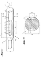
- Fig. 1b has a spigot 1 of one along an axis A rotating and hitting driven tool 2, which along the axis A with a maximum guide diameter D extends, each exactly the same, diametrically arranged, at an Axialverriegelungsende 3 to the free end 4 down axially closed, locking grooves 5 and rotary driving grooves 6 with a both parallel as also perpendicular to the axis A extending tangential force contact surface 7. Between a tool-side guide end 12 with the guide diameter D to a Tool-side groove end 13 of both rotary driving grooves 6 is an axial guide length F formed half of the guide diameter D.
- the groove end 13 is of a tool-side locking end 14 by more than twice the Guide diameter D offset axially on the tool side.
- About a contact length K from Duplicate of the guide diameter D out are both rotary driving grooves 6 with a constant groove width B of one third of the guide diameter D and formed up to a length L which is longer than three times the guide diameter D, the Axialverriegelungsende 3 upstream tool side.
- the locking grooves 5 go in each case on the tool side in the rotary driving grooves 6, wherein a radial groove depth T both rotary driving grooves 6 over the entire contact length K half of the groove width B. is.
- the rotary driving groove 6 with, one third of the guide diameter D. amounting, groove width B of the two, diametrically opposite Locking grooves 5 tool-axially spaced and offset by 90 ° circumferentially, wherein the guide length F is half, the contact length K twice and the length L the 3.5 times the guide diameter D is.
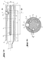
- a mirror-symmetrical insertion end 1 is assigned to an associated, indicated tool holder 8 with rotary driving means in the form of three radially to inside einkragenden, tool side upstream rotary driving webs 9 and a radial displaceable locking means in the form of a locking ball 10 introduced.
- These are the rotary driving grooves 6 with a wider one-fifth of the guide diameter D. constant, constant width B on the machine side to the free front end 4 open.
- the three mirror-symmetrically arranged rotary driving grooves 6 are of the two diametrically opposed locking grooves 5 symmetrically circumferentially offset.
- the Guide length F is the simple, the contact length K is four times and the length L is the 3.5 times the guide diameter D, wherein the groove end 13 of the tool side Locking end 14 twice the guide diameter D axial tool side is offset.
Landscapes
- Engineering & Computer Science (AREA)
- Mechanical Engineering (AREA)
- Percussive Tools And Related Accessories (AREA)
- Drilling Tools (AREA)
Abstract
Description
Claims (11)
- Einsteckende eines zumindest teilweise längs einer Achse (A) drehend und/oder schlagend angetriebenen Werkzeugs (2), welches sich längs der Achse (A) innerhalb eines maximalen Führungsdurchmessers (D) erstreckt sowie zumindest eine, an einem Axialverriegelungsende (3) zum freien Stirnende (4) hin axial geschlossene, Verriegelungsnut (5) und Drehmitnahmenuten (6) mit einer Nutenbreite (B) mit zumindest einer Tangentialkraftkontaktfläche (7) aufweist, dadurch gekennzeichnet, dass zumindest zwei Drehmitnahmenuten (6) bei einer, zumindest dem Dreifachen des Führungsdurchmessers (D) betragenden, Länge (L) dem Axialverriegelungsende (3) werkzeugseitig vorgelagert sowie zumindest über eine, zumindest dem 1.5-fachen des Führungsdurchmessers (D) betragenden, Kontaktlänge (K) breiter als ein Fünftel des Führungsdurchmessers (D) ausgebildet sind.
- Einsteckende nach Anspruch 1, dadurch gekennzeichnet, dass eine axiale Führungslänge (F) zwischen einem werkzeugseitigen Führungsende (12) mit dem Führungsdurchmesser (D) bis zu einem werkzeugseitigen Nutende (13) zumindest zweier Drehmitnahmenuten (6) kleiner dem 1.5-fachen des Führungsdurchmessers (D) ist.
- Einsteckende nach Anspruch 1 oder 2, dadurch gekennzeichnet, dass das Nutende (13) von einem werkzeugseitigen Verriegelungsende (14) zumindest um das 1.5-fache des Führungsdurchmessers (D) axial werkzeugseitig versetzt ist.
- Einsteckende nach einem der Ansprüche 1 bis 3, dadurch gekennzeichnet, dass die Tangentialkraftkontaktfläche (7) zumindest über die Kontaktlänge (K) sowohl parallel als auch senkrecht zur Achse (A) verläuft.
- Einsteckende nach einem der vorherigen Ansprüche, dadurch gekennzeichnet, dass zumindest über die Kontaktlänge (K) eine radiale Nutentiefe (T) jeder Drehmitnahmenut (6) zwischen dem 0.5 bis 1.0 fachen der Nutbreite (B) beträgt.
- Einsteckende nach einem der vorherigen Ansprüche, dadurch gekennzeichnet, dass zumindest drei Drehmitnahmenuten (6) vorhanden sind, die optional spiegelsymmetrisch angeordnet sind.
- Einsteckende nach einem der vorherigen Ansprüche, dadurch gekennzeichnet, dass zwei, diametral versetzte Verriegelungsnuten (5) vorhanden sind.
- Einsteckende nach einem der Ansprüche 1 bis 7, dadurch gekennzeichnet, dass die Verriegelungsnuten (5) werkzeugseitig in die Drehmitnahmenuten (6) übergehen.
- Einsteckende nach einem der vorherigen Ansprüche, dadurch gekennzeichnet, dass die Drehmitnahmenuten (6) von den Verriegelungsnuten (5) werkzeugseitig axial beabstandet sind.
- Einsteckende nach einem der vorherigen Ansprüche, dadurch gekennzeichnet, dass die Drehmitnahmenuten (6) von den Verriegelungsnuten (5) umfänglich versetzt sind, optional symmetrisch umfänglich versetzt.
- Einsteckende nach einem der vorherigen Ansprüche, dadurch gekennzeichnet, dass die Drehmitnahmenuten (6) maschinenseitig offen sind.
Applications Claiming Priority (2)
| Application Number | Priority Date | Filing Date | Title |
|---|---|---|---|
| DE10357380A DE10357380A1 (de) | 2003-12-05 | 2003-12-05 | Einsteckende für ein drehendes und/oder schlagendes Werkzeug |
| DE10357380 | 2003-12-05 |
Publications (3)
| Publication Number | Publication Date |
|---|---|
| EP1537956A2 true EP1537956A2 (de) | 2005-06-08 |
| EP1537956A3 EP1537956A3 (de) | 2006-01-04 |
| EP1537956B1 EP1537956B1 (de) | 2012-01-18 |
Family
ID=34442505
Family Applications (1)
| Application Number | Title | Priority Date | Filing Date |
|---|---|---|---|
| EP04106300A Expired - Lifetime EP1537956B1 (de) | 2003-12-05 | 2004-12-06 | Einsteckende für ein drehendes und/oder schlagendes Werkzeug |
Country Status (12)
| Country | Link |
|---|---|
| US (1) | US7429154B2 (de) |
| EP (1) | EP1537956B1 (de) |
| JP (1) | JP2005169617A (de) |
| KR (1) | KR20050054820A (de) |
| CN (1) | CN1623750A (de) |
| AT (1) | ATE541682T1 (de) |
| AU (1) | AU2004229013A1 (de) |
| CA (1) | CA2487464A1 (de) |
| DE (1) | DE10357380A1 (de) |
| RU (1) | RU2363828C2 (de) |
| TW (1) | TW200536694A (de) |
| ZA (1) | ZA200409789B (de) |
Families Citing this family (15)
| Publication number | Priority date | Publication date | Assignee | Title |
|---|---|---|---|---|
| DE102004054685A1 (de) * | 2004-11-12 | 2006-05-18 | Hilti Ag | Werkzeugaufnahme |
| US20130127123A1 (en) * | 2010-02-15 | 2013-05-23 | Kabushiki Kaisha Miyanaga | Rotation tool installation and removal device and said rotation tool |
| USD782042S1 (en) | 2015-03-25 | 2017-03-21 | Medtronic Ps Medical, Inc. | Surgical tool |
| USD800907S1 (en) | 2015-03-25 | 2017-10-24 | Medtronic Ps Medical, Inc. | Surgical tool |
| USD790699S1 (en) | 2015-03-25 | 2017-06-27 | Medtronic Ps Medical, Inc. | Surgical tool |
| USD800906S1 (en) | 2015-03-25 | 2017-10-24 | Medtronic Ps Medical, Inc. | Surgical tool |
| US10314610B2 (en) | 2015-03-25 | 2019-06-11 | Medtronic Ps Medical, Inc. | Slanted drive axis rotary surgical cutting tools and powered handpieces |
| US10080579B2 (en) | 2015-03-25 | 2018-09-25 | Medtronic Ps Medical, Inc. | Pin drive rotary surgical cutting tools and powered handpieces |
| DE102015005250A1 (de) * | 2015-04-24 | 2016-10-27 | Heule Werkzeug Ag | Bohr-Fas-Kombi-Werkzeug |
| USD800903S1 (en) | 2016-02-09 | 2017-10-24 | Medtronic Ps Medical, Inc. | Surgical tool |
| US10849634B2 (en) | 2018-06-20 | 2020-12-01 | Medtronic Xomed, Inc. | Coupling portion for rotary surgical cutting systems |
| CN109909521B (zh) * | 2019-04-08 | 2024-01-16 | 台州市开宇冶金机具有限公司 | 凿岩柱齿钎头注水孔多工位加工机 |
| USD927949S1 (en) * | 2019-11-06 | 2021-08-17 | Glendo Llc | Graver tool |
| US12582415B2 (en) | 2022-11-16 | 2026-03-24 | Medtronic Ps Medical, Inc. | Oscillating surgical bone removal tool with fluted cutting head |
| DE102023114119A1 (de) | 2023-05-30 | 2025-01-02 | Kleine Holding Gmbh | Einsteckende eines Werkzeugs, betreffendes Herstellungsverfahren und Werkzeugaufnahme |
Citations (1)
| Publication number | Priority date | Publication date | Assignee | Title |
|---|---|---|---|---|
| DE4338818A1 (de) | 1993-11-13 | 1995-05-18 | Hawera Probst Kg Hartmetall | Einrichtung an Handwerkzeugmaschinen zur Drehmomentübertragung |
Family Cites Families (22)
| Publication number | Priority date | Publication date | Assignee | Title |
|---|---|---|---|---|
| DE7536182U (de) * | 1975-11-14 | 1978-02-02 | Robert Bosch Gmbh, 7000 Stuttgart | Einrichtung zur drehmomentuebertragung |
| DE3205063C2 (de) * | 1981-04-03 | 1986-10-09 | Robert Bosch Gmbh, 7000 Stuttgart | Werkzeughalter |
| DE3429419A1 (de) * | 1984-08-09 | 1986-02-20 | Hilti Ag, Schaan | Bohrwerkzeug fuer handbohrmaschinen |
| DE3745046C2 (de) | 1987-05-20 | 1996-07-25 | Bosch Gmbh Robert | Werkzeugaufnahme einer Handwerkzeugmaschine mit verdrehsicher einsetzbarem Werkzeug |
| DE3824894A1 (de) * | 1988-07-22 | 1990-01-25 | Bosch Gmbh Robert | Einrichtung an handwerkzeugmaschinen zur drehmomentuebertragung |
| DE3941646A1 (de) * | 1989-12-16 | 1991-06-20 | Heller Werkzeug Gmbh Geb | Werkzeug zum schlagbohren und werkzeugaufnahme fuer schlagbohrende werkzeuge |
| SU1747260A1 (ru) * | 1989-12-20 | 1992-07-15 | Московское Научно-Производственное Объединение По Механизированному Строительному Инструменту И Отделочным Машинам | Устройство креплени рабочего инструмента |
| DE4141846A1 (de) * | 1991-12-18 | 1993-06-24 | Hilti Ag | Werkzeug zum schlagbohren und meisseln und werkzeugaufnahme fuer diese werkzeuge |
| DK30592D0 (da) * | 1992-03-06 | 1992-03-06 | Joran Bor A S | Boropsaetning |
| DE4222744A1 (de) * | 1992-07-10 | 1994-01-13 | Hilti Ag | Werkzeug und Werkzeugaufnahme für Handwerkzeuggeräte |
| DE4242452A1 (de) * | 1992-07-15 | 1994-01-20 | Hilti Ag | Werkzeug und Werkzeugaufnahme für Handwerkzeuggeräte |
| DE4223518A1 (de) * | 1992-07-17 | 1994-01-20 | Hilti Ag | Werkzeug und Werkzeugaufnahme für Handwerkzeuggeräte |
| DE4227949A1 (de) * | 1992-08-22 | 1994-02-24 | Bosch Gmbh Robert | Werkzeug für Handwerkzeugmaschinen |
| DE4303545A1 (de) | 1993-02-08 | 1994-08-11 | Hawera Probst Kg Hartmetall | Einrichtung an Handwerkzeugmaschinen zur Drehmomentübertragung |
| DE4313578A1 (de) * | 1993-03-06 | 1994-09-08 | Hilti Ag | Werkzeug und Werkzeugaufnahme für Handwerkzeuggeräte |
| DE4313580A1 (de) * | 1993-04-26 | 1994-10-27 | Hilti Ag | Werkzeugeinspannschaft |
| DE4340728C1 (de) * | 1993-11-30 | 1995-01-26 | Bosch Gmbh Robert | Einrichtung an Handwerkzeugmaschinen zur Drehmitnahme von Werkzeugen |
| DE59409686D1 (de) * | 1994-01-14 | 2001-04-19 | Bosch Gmbh Robert | Einrichtung an handwerkzeugmaschinen zur drehmitnahme von werkzeugen |
| DK9400350U3 (da) | 1994-09-13 | 1995-12-13 | American Tool Comp Inc | Boreopsætning for hammermaskiner |
| AUPP053097A0 (en) | 1997-11-26 | 1997-12-18 | Ramset Fasteners (Aust.) Pty. Limited | Drill bits and holders therefor |
| DE19819631A1 (de) * | 1998-05-04 | 1999-11-11 | Hilti Ag | Werkzeug für Handwerkzeugmaschinen |
| US6651990B2 (en) * | 2001-08-06 | 2003-11-25 | Ryobi Ltd. | Tool holder |
-
2003
- 2003-12-05 DE DE10357380A patent/DE10357380A1/de not_active Withdrawn
-
2004
- 2004-11-09 AU AU2004229013A patent/AU2004229013A1/en not_active Abandoned
- 2004-11-09 CA CA002487464A patent/CA2487464A1/en not_active Abandoned
- 2004-11-10 KR KR1020040091387A patent/KR20050054820A/ko not_active Withdrawn
- 2004-12-02 ZA ZA2004/09789A patent/ZA200409789B/en unknown
- 2004-12-02 CN CNA2004100979615A patent/CN1623750A/zh active Pending
- 2004-12-02 US US11/002,171 patent/US7429154B2/en active Active
- 2004-12-03 JP JP2004350994A patent/JP2005169617A/ja active Pending
- 2004-12-03 TW TW093137292A patent/TW200536694A/zh unknown
- 2004-12-03 RU RU2004135349/03A patent/RU2363828C2/ru not_active IP Right Cessation
- 2004-12-06 EP EP04106300A patent/EP1537956B1/de not_active Expired - Lifetime
- 2004-12-06 AT AT04106300T patent/ATE541682T1/de active
Patent Citations (1)
| Publication number | Priority date | Publication date | Assignee | Title |
|---|---|---|---|---|
| DE4338818A1 (de) | 1993-11-13 | 1995-05-18 | Hawera Probst Kg Hartmetall | Einrichtung an Handwerkzeugmaschinen zur Drehmomentübertragung |
Also Published As
| Publication number | Publication date |
|---|---|
| RU2004135349A (ru) | 2006-05-10 |
| TW200536694A (en) | 2005-11-16 |
| US20050141972A1 (en) | 2005-06-30 |
| EP1537956A3 (de) | 2006-01-04 |
| DE10357380A1 (de) | 2005-06-30 |
| AU2004229013A1 (en) | 2005-06-23 |
| CN1623750A (zh) | 2005-06-08 |
| US7429154B2 (en) | 2008-09-30 |
| JP2005169617A (ja) | 2005-06-30 |
| KR20050054820A (ko) | 2005-06-10 |
| ATE541682T1 (de) | 2012-02-15 |
| CA2487464A1 (en) | 2005-06-05 |
| RU2363828C2 (ru) | 2009-08-10 |
| EP1537956B1 (de) | 2012-01-18 |
| ZA200409789B (en) | 2005-09-28 |
Similar Documents
| Publication | Publication Date | Title |
|---|---|---|
| EP1602452B1 (de) | Einsteckende für ein drehendes und/oder schlagendes Werkzeug | |
| EP1537956B1 (de) | Einsteckende für ein drehendes und/oder schlagendes Werkzeug | |
| EP0281997B1 (de) | Gesteinsbohrer | |
| EP1125663B1 (de) | Bohrwerkzeug für Gestein | |
| EP0357648A1 (de) | Einrichtung an handwerkzeugmaschinen zur drehmomentübertragung. | |
| DE2444899A1 (de) | Bohrwerkzeug mit bohrer und aufnahmeteil | |
| WO2002020224A1 (de) | Werkzeughalterung für eine handwerkzeugmaschine | |
| EP2295206A2 (de) | Elektrische Kombi-Handwerkzeugmaschine | |
| EP0937860B1 (de) | Bohr- und/oder Meisselwerkzeug | |
| DE10241054A1 (de) | Werkzeug und Werkzeughalter für eine Handwerkzeugmaschine | |
| EP0739267B1 (de) | Einrichtung an handwerkzeugmaschinen zur drehmitnahme von werkzeugen | |
| DE3310147C2 (de) | ||
| EP0548008B1 (de) | Werkzeug zum Schlagbohren und Meisseln und Werkzeugaufnahme für diese Werkzeuge | |
| DE202013003876U1 (de) | Brechwerkzeug | |
| DE4400969A1 (de) | Einrichtung an Handwerkzeugmaschinen zur Drehmitnahme von Werkzeugen | |
| EP1382409B1 (de) | Betonbohrer | |
| EP0808696B1 (de) | Befestigungssystem und Verfahren zur Erstellung von Befestigungen | |
| EP2199531A2 (de) | Bohrkopf für Gesteinsbohrer | |
| EP1535704B1 (de) | Werkzeugaufnahme für ein drehendes und schlagendes Werkzeug | |
| EP1375078A1 (de) | Einsteckende und Werkzeugaufnahme für ein drehendes und schlagendes Werkzeug | |
| DE19721857A1 (de) | Spreizanker | |
| EP1251238A1 (de) | Schlagbohrwerkzeug für Gestein | |
| DE3613264C2 (de) | Bohrwerkzeug zum drehenden Bohren | |
| EP1877227B1 (de) | Einsatzwerkzeug und werkzeughalter für eine handwerkzeugmaschine | |
| DE3504917A1 (de) | Halterung an bohrhaemmern oder schlagbohrmaschinen |
Legal Events
| Date | Code | Title | Description |
|---|---|---|---|
| PUAI | Public reference made under article 153(3) epc to a published international application that has entered the european phase |
Free format text: ORIGINAL CODE: 0009012 |
|
| AK | Designated contracting states |
Kind code of ref document: A2 Designated state(s): AT BE BG CH CY CZ DE DK EE ES FI FR GB GR HU IE IS IT LI LT LU MC NL PL PT RO SE SI SK TR |
|
| AX | Request for extension of the european patent |
Extension state: AL BA HR LV MK YU |
|
| PUAL | Search report despatched |
Free format text: ORIGINAL CODE: 0009013 |
|
| AK | Designated contracting states |
Kind code of ref document: A3 Designated state(s): AT BE BG CH CY CZ DE DK EE ES FI FR GB GR HU IE IS IT LI LT LU MC NL PL PT RO SE SI SK TR |
|
| AX | Request for extension of the european patent |
Extension state: AL BA HR LV MK YU |
|
| 17P | Request for examination filed |
Effective date: 20060704 |
|
| AKX | Designation fees paid |
Designated state(s): AT BE BG CH CY CZ DE DK EE ES FI FR GB GR HU IE IS IT LI LT LU MC NL PL PT RO SE SI SK TR |
|
| 17Q | First examination report despatched |
Effective date: 20061103 |
|
| GRAP | Despatch of communication of intention to grant a patent |
Free format text: ORIGINAL CODE: EPIDOSNIGR1 |
|
| GRAS | Grant fee paid |
Free format text: ORIGINAL CODE: EPIDOSNIGR3 |
|
| GRAA | (expected) grant |
Free format text: ORIGINAL CODE: 0009210 |
|
| AK | Designated contracting states |
Kind code of ref document: B1 Designated state(s): AT BE BG CH CY CZ DE DK EE ES FI FR GB GR HU IE IS IT LI LT LU MC NL PL PT RO SE SI SK TR |
|
| REG | Reference to a national code |
Ref country code: GB Ref legal event code: FG4D Free format text: NOT ENGLISH |
|
| REG | Reference to a national code |
Ref country code: CH Ref legal event code: EP |
|
| REG | Reference to a national code |
Ref country code: IE Ref legal event code: FG4D Free format text: LANGUAGE OF EP DOCUMENT: GERMAN Ref country code: AT Ref legal event code: REF Ref document number: 541682 Country of ref document: AT Kind code of ref document: T Effective date: 20120215 |
|
| REG | Reference to a national code |
Ref country code: DE Ref legal event code: R096 Ref document number: 502004013242 Country of ref document: DE Effective date: 20120315 |
|
| REG | Reference to a national code |
Ref country code: NL Ref legal event code: VDEP Effective date: 20120118 |
|
| LTIE | Lt: invalidation of european patent or patent extension |
Effective date: 20120118 |
|
| PG25 | Lapsed in a contracting state [announced via postgrant information from national office to epo] |
Ref country code: NL Free format text: LAPSE BECAUSE OF FAILURE TO SUBMIT A TRANSLATION OF THE DESCRIPTION OR TO PAY THE FEE WITHIN THE PRESCRIBED TIME-LIMIT Effective date: 20120118 Ref country code: LT Free format text: LAPSE BECAUSE OF FAILURE TO SUBMIT A TRANSLATION OF THE DESCRIPTION OR TO PAY THE FEE WITHIN THE PRESCRIBED TIME-LIMIT Effective date: 20120118 Ref country code: IS Free format text: LAPSE BECAUSE OF FAILURE TO SUBMIT A TRANSLATION OF THE DESCRIPTION OR TO PAY THE FEE WITHIN THE PRESCRIBED TIME-LIMIT Effective date: 20120518 Ref country code: BG Free format text: LAPSE BECAUSE OF FAILURE TO SUBMIT A TRANSLATION OF THE DESCRIPTION OR TO PAY THE FEE WITHIN THE PRESCRIBED TIME-LIMIT Effective date: 20120418 |
|
| REG | Reference to a national code |
Ref country code: IE Ref legal event code: FD4D |
|
| PG25 | Lapsed in a contracting state [announced via postgrant information from national office to epo] |
Ref country code: FI Free format text: LAPSE BECAUSE OF FAILURE TO SUBMIT A TRANSLATION OF THE DESCRIPTION OR TO PAY THE FEE WITHIN THE PRESCRIBED TIME-LIMIT Effective date: 20120118 Ref country code: PL Free format text: LAPSE BECAUSE OF FAILURE TO SUBMIT A TRANSLATION OF THE DESCRIPTION OR TO PAY THE FEE WITHIN THE PRESCRIBED TIME-LIMIT Effective date: 20120118 Ref country code: PT Free format text: LAPSE BECAUSE OF FAILURE TO SUBMIT A TRANSLATION OF THE DESCRIPTION OR TO PAY THE FEE WITHIN THE PRESCRIBED TIME-LIMIT Effective date: 20120518 Ref country code: GR Free format text: LAPSE BECAUSE OF FAILURE TO SUBMIT A TRANSLATION OF THE DESCRIPTION OR TO PAY THE FEE WITHIN THE PRESCRIBED TIME-LIMIT Effective date: 20120419 |
|
| PG25 | Lapsed in a contracting state [announced via postgrant information from national office to epo] |
Ref country code: CY Free format text: LAPSE BECAUSE OF FAILURE TO SUBMIT A TRANSLATION OF THE DESCRIPTION OR TO PAY THE FEE WITHIN THE PRESCRIBED TIME-LIMIT Effective date: 20120118 |
|
| PG25 | Lapsed in a contracting state [announced via postgrant information from national office to epo] |
Ref country code: DK Free format text: LAPSE BECAUSE OF FAILURE TO SUBMIT A TRANSLATION OF THE DESCRIPTION OR TO PAY THE FEE WITHIN THE PRESCRIBED TIME-LIMIT Effective date: 20120118 Ref country code: RO Free format text: LAPSE BECAUSE OF FAILURE TO SUBMIT A TRANSLATION OF THE DESCRIPTION OR TO PAY THE FEE WITHIN THE PRESCRIBED TIME-LIMIT Effective date: 20120118 Ref country code: SI Free format text: LAPSE BECAUSE OF FAILURE TO SUBMIT A TRANSLATION OF THE DESCRIPTION OR TO PAY THE FEE WITHIN THE PRESCRIBED TIME-LIMIT Effective date: 20120118 Ref country code: CZ Free format text: LAPSE BECAUSE OF FAILURE TO SUBMIT A TRANSLATION OF THE DESCRIPTION OR TO PAY THE FEE WITHIN THE PRESCRIBED TIME-LIMIT Effective date: 20120118 Ref country code: EE Free format text: LAPSE BECAUSE OF FAILURE TO SUBMIT A TRANSLATION OF THE DESCRIPTION OR TO PAY THE FEE WITHIN THE PRESCRIBED TIME-LIMIT Effective date: 20120118 Ref country code: SE Free format text: LAPSE BECAUSE OF FAILURE TO SUBMIT A TRANSLATION OF THE DESCRIPTION OR TO PAY THE FEE WITHIN THE PRESCRIBED TIME-LIMIT Effective date: 20120118 Ref country code: IE Free format text: LAPSE BECAUSE OF FAILURE TO SUBMIT A TRANSLATION OF THE DESCRIPTION OR TO PAY THE FEE WITHIN THE PRESCRIBED TIME-LIMIT Effective date: 20120118 |
|
| PLBE | No opposition filed within time limit |
Free format text: ORIGINAL CODE: 0009261 |
|
| STAA | Information on the status of an ep patent application or granted ep patent |
Free format text: STATUS: NO OPPOSITION FILED WITHIN TIME LIMIT |
|
| PG25 | Lapsed in a contracting state [announced via postgrant information from national office to epo] |
Ref country code: IT Free format text: LAPSE BECAUSE OF FAILURE TO SUBMIT A TRANSLATION OF THE DESCRIPTION OR TO PAY THE FEE WITHIN THE PRESCRIBED TIME-LIMIT Effective date: 20120118 Ref country code: SK Free format text: LAPSE BECAUSE OF FAILURE TO SUBMIT A TRANSLATION OF THE DESCRIPTION OR TO PAY THE FEE WITHIN THE PRESCRIBED TIME-LIMIT Effective date: 20120118 |
|
| 26N | No opposition filed |
Effective date: 20121019 |
|
| REG | Reference to a national code |
Ref country code: DE Ref legal event code: R097 Ref document number: 502004013242 Country of ref document: DE Effective date: 20121019 |
|
| PG25 | Lapsed in a contracting state [announced via postgrant information from national office to epo] |
Ref country code: ES Free format text: LAPSE BECAUSE OF FAILURE TO SUBMIT A TRANSLATION OF THE DESCRIPTION OR TO PAY THE FEE WITHIN THE PRESCRIBED TIME-LIMIT Effective date: 20120429 |
|
| BERE | Be: lapsed |
Owner name: HILTI AKTIENGESELLSCHAFT Effective date: 20121231 |
|
| PG25 | Lapsed in a contracting state [announced via postgrant information from national office to epo] |
Ref country code: MC Free format text: LAPSE BECAUSE OF NON-PAYMENT OF DUE FEES Effective date: 20121231 |
|
| REG | Reference to a national code |
Ref country code: CH Ref legal event code: PL |
|
| GBPC | Gb: european patent ceased through non-payment of renewal fee |
Effective date: 20121206 |
|
| REG | Reference to a national code |
Ref country code: FR Ref legal event code: ST Effective date: 20130830 |
|
| PG25 | Lapsed in a contracting state [announced via postgrant information from national office to epo] |
Ref country code: BE Free format text: LAPSE BECAUSE OF NON-PAYMENT OF DUE FEES Effective date: 20121231 |
|
| PG25 | Lapsed in a contracting state [announced via postgrant information from national office to epo] |
Ref country code: CH Free format text: LAPSE BECAUSE OF NON-PAYMENT OF DUE FEES Effective date: 20121231 Ref country code: LI Free format text: LAPSE BECAUSE OF NON-PAYMENT OF DUE FEES Effective date: 20121231 |
|
| PG25 | Lapsed in a contracting state [announced via postgrant information from national office to epo] |
Ref country code: GB Free format text: LAPSE BECAUSE OF NON-PAYMENT OF DUE FEES Effective date: 20121206 Ref country code: FR Free format text: LAPSE BECAUSE OF NON-PAYMENT OF DUE FEES Effective date: 20130102 |
|
| REG | Reference to a national code |
Ref country code: AT Ref legal event code: MM01 Ref document number: 541682 Country of ref document: AT Kind code of ref document: T Effective date: 20121206 |
|
| PG25 | Lapsed in a contracting state [announced via postgrant information from national office to epo] |
Ref country code: TR Free format text: LAPSE BECAUSE OF FAILURE TO SUBMIT A TRANSLATION OF THE DESCRIPTION OR TO PAY THE FEE WITHIN THE PRESCRIBED TIME-LIMIT Effective date: 20120118 |
|
| PG25 | Lapsed in a contracting state [announced via postgrant information from national office to epo] |
Ref country code: AT Free format text: LAPSE BECAUSE OF NON-PAYMENT OF DUE FEES Effective date: 20121206 Ref country code: LU Free format text: LAPSE BECAUSE OF NON-PAYMENT OF DUE FEES Effective date: 20121206 |
|
| PG25 | Lapsed in a contracting state [announced via postgrant information from national office to epo] |
Ref country code: HU Free format text: LAPSE BECAUSE OF FAILURE TO SUBMIT A TRANSLATION OF THE DESCRIPTION OR TO PAY THE FEE WITHIN THE PRESCRIBED TIME-LIMIT Effective date: 20041206 |
|
| PGFP | Annual fee paid to national office [announced via postgrant information from national office to epo] |
Ref country code: DE Payment date: 20191210 Year of fee payment: 16 |
|
| REG | Reference to a national code |
Ref country code: DE Ref legal event code: R119 Ref document number: 502004013242 Country of ref document: DE |
|
| PG25 | Lapsed in a contracting state [announced via postgrant information from national office to epo] |
Ref country code: DE Free format text: LAPSE BECAUSE OF NON-PAYMENT OF DUE FEES Effective date: 20210701 |