EP1537808B1 - Machine à café et four à micro-ondes et procédé de commande associé - Google Patents
Machine à café et four à micro-ondes et procédé de commande associé Download PDFInfo
- Publication number
- EP1537808B1 EP1537808B1 EP04028343A EP04028343A EP1537808B1 EP 1537808 B1 EP1537808 B1 EP 1537808B1 EP 04028343 A EP04028343 A EP 04028343A EP 04028343 A EP04028343 A EP 04028343A EP 1537808 B1 EP1537808 B1 EP 1537808B1
- Authority
- EP
- European Patent Office
- Prior art keywords
- heater
- temperature
- tube
- coffee maker
- microwave oven
- Prior art date
- Legal status (The legal status is an assumption and is not a legal conclusion. Google has not performed a legal analysis and makes no representation as to the accuracy of the status listed.)
- Not-in-force
Links
- 238000000034 method Methods 0.000 title description 8
- XLYOFNOQVPJJNP-UHFFFAOYSA-N water Substances O XLYOFNOQVPJJNP-UHFFFAOYSA-N 0.000 claims description 36
- 235000012206 bottled water Nutrition 0.000 claims description 17
- 239000003651 drinking water Substances 0.000 claims description 17
- 239000000919 ceramic Substances 0.000 claims description 2
- 230000008878 coupling Effects 0.000 claims 1
- 238000010168 coupling process Methods 0.000 claims 1
- 238000005859 coupling reaction Methods 0.000 claims 1
- 238000010438 heat treatment Methods 0.000 claims 1
- 238000013021 overheating Methods 0.000 description 11
- 235000013305 food Nutrition 0.000 description 4
- 239000000463 material Substances 0.000 description 2
- 239000000843 powder Substances 0.000 description 2
- 238000010411 cooking Methods 0.000 description 1
- 239000011521 glass Substances 0.000 description 1
- 238000003780 insertion Methods 0.000 description 1
- 230000037431 insertion Effects 0.000 description 1
- 239000002184 metal Substances 0.000 description 1
- 239000004745 nonwoven fabric Substances 0.000 description 1
Images


Classifications
-
- A—HUMAN NECESSITIES
- A47—FURNITURE; DOMESTIC ARTICLES OR APPLIANCES; COFFEE MILLS; SPICE MILLS; SUCTION CLEANERS IN GENERAL
- A47J—KITCHEN EQUIPMENT; COFFEE MILLS; SPICE MILLS; APPARATUS FOR MAKING BEVERAGES
- A47J31/00—Apparatus for making beverages
- A47J31/44—Parts or details or accessories of beverage-making apparatus
- A47J31/54—Water boiling vessels in beverage making machines
- A47J31/547—Water boiling vessels in beverage making machines using microwave energy for heating the water
-
- A—HUMAN NECESSITIES
- A47—FURNITURE; DOMESTIC ARTICLES OR APPLIANCES; COFFEE MILLS; SPICE MILLS; SUCTION CLEANERS IN GENERAL
- A47J—KITCHEN EQUIPMENT; COFFEE MILLS; SPICE MILLS; APPARATUS FOR MAKING BEVERAGES
- A47J31/00—Apparatus for making beverages
- A47J31/04—Coffee-making apparatus with rising pipes
- A47J31/057—Coffee-making apparatus with rising pipes with water container separated from beverage container, the hot water passing the filter only once i.e. classical type of drip coffee makers
- A47J31/0573—Coffee-making apparatus with rising pipes with water container separated from beverage container, the hot water passing the filter only once i.e. classical type of drip coffee makers with flow through heaters
-
- A—HUMAN NECESSITIES
- A47—FURNITURE; DOMESTIC ARTICLES OR APPLIANCES; COFFEE MILLS; SPICE MILLS; SUCTION CLEANERS IN GENERAL
- A47J—KITCHEN EQUIPMENT; COFFEE MILLS; SPICE MILLS; APPARATUS FOR MAKING BEVERAGES
- A47J31/00—Apparatus for making beverages
- A47J31/44—Parts or details or accessories of beverage-making apparatus
- A47J31/54—Water boiling vessels in beverage making machines
- A47J31/542—Continuous-flow heaters
- A47J31/545—Control or safety devices
-
- A—HUMAN NECESSITIES
- A47—FURNITURE; DOMESTIC ARTICLES OR APPLIANCES; COFFEE MILLS; SPICE MILLS; SUCTION CLEANERS IN GENERAL
- A47J—KITCHEN EQUIPMENT; COFFEE MILLS; SPICE MILLS; APPARATUS FOR MAKING BEVERAGES
- A47J31/00—Apparatus for making beverages
- A47J31/44—Parts or details or accessories of beverage-making apparatus
- A47J31/54—Water boiling vessels in beverage making machines
- A47J31/56—Water boiling vessels in beverage making machines having water-level controls; having temperature controls
-
- A—HUMAN NECESSITIES
- A47—FURNITURE; DOMESTIC ARTICLES OR APPLIANCES; COFFEE MILLS; SPICE MILLS; SUCTION CLEANERS IN GENERAL
- A47J—KITCHEN EQUIPMENT; COFFEE MILLS; SPICE MILLS; APPARATUS FOR MAKING BEVERAGES
- A47J36/00—Parts, details or accessories of cooking-vessels
- A47J36/02—Selection of specific materials, e.g. heavy bottoms with copper inlay or with insulating inlay
- A47J36/027—Cooking- or baking-vessels specially adapted for use in microwave ovens; Accessories therefor
Definitions
- the present invention relates to coffee maker and microwave ovens, and more particularly, to a heater assembly for a coffee maker and microwave oven and a method for controlling the same which can prevent electric components suffering from damage caused by overheating of a heater.
- a microwave oven cooks food with intermolecular frictional heat generated as a high frequency wave (about 2,450MHz) disturbs molecular arrangement of the food.
- the microwave oven heats the food with the high frequency wave, the microwave oven cannot cook various kinds of food. For an example, coffee people enjoys to drink, cannot be prepared with the microwave oven, to require a coffee maker, separately.
- EP-A-1343356 describes a coffee maker and microwave oven including a heater assembly on which the preamble position of claim 1 is based.
- the present invention is directed to a heater assembly for a coffee maker and microwave oven as disclosed in claim 1, and to a coffee maker and microwave oven as disclosed in claim 6.
- FIX 1 illustrates a section of a coffee maker and microwave oven in accordance with a first preferred embodiment of the present invention
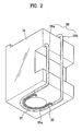
- FIG 2 illustrates a bottom perspective view of a coffee maker unit in FIG 1;
- FIG 3 illustrates a perspective view of a coffee maker and microwave oven in accordance with a second preferred embodiment of the present invention
- FIG 4 illustrates a perspective view of a coffee maker and microwave oven in accordance with a third preferred embodiment of the present invention
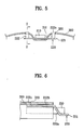
- FIGS. 5 and 6 illustrate sections each showing a state a temperature sensing unit in accordance with a third preferred embodiment of the present invention is mounted on a plate;
- FIG 7 illustrates a flow chart showing the steps of a method for controlling a coffee maker and microwave oven in accordance with a preferred embodiment of the present invention.
- FIG 1 illustrates a section of a coffee maker and microwave oven in accordance with a first preferred embodiment of the present invention
- FIG 2 illustrates a bottom perspective view of a coffee maker unit in the coffee maker and microwave oven in FIG 1.
- the coffee maker and microwave oven includes a cabinet 10 forming an exterior, an outfit room 20 in the cabinet 10, and a coffee maker unit 30 at one side of the outfit room 20.
- a magnetron 21 receives an external high voltage power, and generates a microwave
- the high voltage transformer 22 transforms external power to high voltage power, before application to the magnetron 21.
- the convection fan 23 cools down various components in the outfit room 20, and blow hot air to a cooking chamber (not shown).
- the coffee maker unit 30 includes a case 31 at one side of the outfit room 20, a water tank 32, a funnel 33, a water supply pipe 36, a water tube 37, and a heater tube 35.
- the case 31 forms an exterior, and the water tank 32 at an upper portion of the case 21 for storing potable water.
- the funnel 33 under the water tank 32 has a filter (not shown) for extracting coffee.
- the funnel 33 has a shape of a cone having a great upper inside diameter, and a small lower inside diameter.
- a filter (not shown) of paper of non-woven fabric placed on an inside, on which coffee powder is filled.
- a jug 34 as a container for storing coffee.
- the jug 34 has an opened top with a hand grip 34a at one side.
- the user can put the jug 34 inside of the case 31, or take the jug 34 out of the case 31, easily.
- the jug 34 is formed of transparent glass or plastic for the user to see a level of the coffee in the jug 34.
- the water supply pipe 36 supplies the potable water from the water tank 32 to the funnel 33.
- the water supply pipe 36 has a first pipe 36a connected to the water tank 32, and a second pipe 36b for supplying potable water to the funnel 33, directly.
- the water supply tube 37 is mounted on a bottom of the case 31, and has one end connected to the first pipe 36a, and the other end connected to the second pipe 36b. Therefore, the potable water in the water tank 32 is supplied to the funnel 33 through the first j pipe 36a, the water supply tube 37, and the second pipe 36b.
- the heater tube 35 is in contact with the water supply tube 37, and has a heater 35a provided therein. Upon putting the coffee maker unit 30 into operation, the heater 35a generates heat at a high temperature, to heat the potable water passing through the water supply tube 37.
- the potable water guided to the water supply tube 37 through the first pipe 36a is heated by the heater 35a and supplied to the funnel 33 via the second pipe 36b.
- the heater tube 35 is formed of a material having a good heat conductivity for smooth conduction of heat from the heater 35a. In detail, it is preferable that the heater tube 35 is formed of ceramic.
- the heater 35a also heats the jug 34 placed on the bottom of the case 31. Therefore, the coffee in the jug 34 always maintains a warm state by the heat from the heater 35a.
- the heater 35a is put into operation in a state no potable water is supplied to the tube 37, the heater 35a is overheated.
- the heater 35a owing to a high temperature of the heater 35, not only an inside temperature of the coffee maker unit 30, but also an inside temperature of the outfit room 20 rise high to damage electric parts, such as the magnetron 21, the high voltage transformer 22, and so on.
- the coffee maker and microwave oven of the present invention is provided with separate temperature measuring means for preventing the heater 35a from overheating.
- FIG 3 illustrates a perspective view of a coffee maker and microwave oven in accordance with a second preferred embodiment of the present invention.
- the coffee maker and microwave oven includes a sensing unit 100 provided in the vicinity of the heater tube 37, for measuring a temperature of the heater 35a.
- the temperature sensing unit 100 is fastened to the bottom of the case 31 at a location spaced a distance from the heater tube 37.
- the temperature sensing unit 100 measures a temperature of the heater 35a, to sense rapid temperature rise of the heater 35, i.e., overheating of the heater 35a, caused by shortage of the potable water in advance.
- the temperature sensing unit 100 measures the temperature of the heater 35a periodically, and transmits a temperature value of the heater 35a to the control unit (not shown) which controls operation of the coffee maker unit 30.
- control unit reads the temperature value of the heater 35a from the temperature sensing unit 100, and cuts off power supply to the heater 35a, if it is determined that the temperature of the heater 35a rises rapidly. According to this, overheating of the heater 35a is prevented, to prevent the electric parts suffering from damage caused by overheating of the heater 35a.
- the temperature sensing unit 100 may be mounted, not in the vicinity of the heater tube, but on an outside surface of the heater tube 37. In this case, the temperature sensing unit 100 can measure the temperature of the heater 35a more accurately.
- the temperature sensing unit 100 can measure a temperature change of the heater 35a without delay.
- the temperature of the heater 35a drops or rises very rapidly at the time of putting the heater 35 into operation, or stopping operation of the heater 35a, when if the temperature sensing unit 100 measure the rapid temperature change of the heater 35a, and transmits to the control unit without delay, the control unit cuts off power to the heater 35a to stop operation of the coffee maker unit unnecessarily, even if the heater 35a is not overheated.
- the temperature sensing unit 100 is spaced a distance away from the heater tube 37.
- FIG. 4 illustrates a perspective view of a coffee maker and microwave oven in accordance with a third preferred embodiment of the present invention.
- the coffee maker and microwave oven includes a water supply tube 37 on a bottom of the case 31 (see FIG. 2), and a heater assembly.
- the heater assembly includes a heater tube 35, a heater in the heater tube 35, and a temperature sensing unit 200.
- the heater tube 35 is in contact with the water supply tube 37, for the heater 35a to heat the potable water passing through the water supply tube 37.
- the temperature sensing unit 200 is mounted in the vicinity of the heater tube 35, for measuring a temperature of the heater 35a.
- the heater assembly further includes a plate 300 for mounting the temperature sensing unit 200 thereon.
- the plate 300 is semicircular, and mounted on an inner side of the heater tube 35.
- the heater tube 35 is secured to an outside circumferential surface of the plate 300, and the water supply tube 37 is positioned on an outer side of the heater tube 35.
- the plate 300 has a securing recess 310 for inserting the temperature sensing unit 200.
- the securing recess 310 is recessed to form a space for inserting the temperature sensing unit 200 therein.
- the temperature sensing unit 200 is inserted in the securing recess 310 of the plate 300, for measuring the temperature of the heater 35a in a state the temperature sensing unit 200 is in close contact with the plate 300.
- the temperature sensing unit 200 measures the temperature of the heater 35a, not directly, but indirectly through heat of the heater 35a transmitted through the plate 300. Therefore, it is preferable that the plate 300 is formed of a material having a good heat conductivity. However, taking production cost into account, the plate 300 may be formed of a general metal.
- the temperature sensing unit 200 includes a temperature sensor 210 for measuring the temperature of the heater 35a, and a sensor coupler 220 for securing the temperature sensor 210 to the plate 300.
- the temperature senor 210 is a thermistor of which internal resistance varies with a temperature, and the temperature sensor 210 and the sensor coupler 220 are formed as a unit.
- the sensor coupler 220 includes a supporter 221 joined with the temperature sensor 210, and one pair of hooks 222 extended from opposite ends, respectively. On opposite sides of the securing recess 310 of the plate 300, there are one pair of fastening holes 320 for inserting the one pair of hooks 222 therein.
- the hook 222 includes a first extension 222a extended upward from the supporter 221 at an angle, a second extension 222b extended from the first extension 222a in a horizontal direction, and a projection 222c at an end of the second extension 222b for insertion in the fastening hole 320.
- FIGS. 5 and 6 illustrate sections each showing a state a temperature sensing unit in accordance with a third preferred embodiment of the present invention is mounted on a plate.
- the temperature sensor 210 upon mounting the sensor coupler 220 to the plate 300, the temperature sensor 210 is placed in the securing recess 310 on an upper surface of the plate 300, and the hooks 222 exert force from an underside of the plate to upward, such that the projection 222c is inserted in the fastening hole 320.
- the temperature sensing unit 200 can be secured to the plate 300.
- the temperature sensing unit 200 can be dismounted from the plate 300, easily.
- a method for controlling a coffee maker and microwave oven in accordance with a present invention will be described in detail, in which an heater 35a is prevented from overheating by using the temperature sensing unit 100, or 200.
- FIG. 7 illustrates a flow chart showing the steps of a method for controlling a coffee maker and microwave oven in accordance with a preferred embodiment of the present invention.
- the control unit supplies potable water from the water tank 32 to the funnel 33 through the water supply pipes 36a, and 36b, and the water supply tube 37, and puts the heater 35a in the heater tube 35 in contact with the water supply tube 37 into operation, to heat the potable water passing through the water supply tube 37 (S200).
- the temperature sensing unit 200 in the vicinity of the heater tube 35 measures a temperature T of the heater 35a, periodically (S300).
- the temperature T of the heater 35a measured at the temperature sensing unit 200 is transmitted to the control unit.
- the control unit calculates a rate of temperature change of the heater 35a (S400), according to the following equation.
- T n denotes the heater temperature measured at a t n time
- T n-1 denotes the heater temperature measured at a t n-1 time.
- the rate DT of the temperature change of the heater 35a is determined of being higher than a preset value (S500).
- an error message is expressed if the rate of temperature change of the heater 35a is higher than the preset value, so that the user is able to know the overheating of the heater 35a, immediately.
- the steps of calculating the rate ⁇ T of the temperature change of the heater 35a is repeated, to determine if the rate ⁇ T of the temperature change of the heater 35a is higher than the preset value.
- the coffee maker and microwave oven and the method for controlling the same of the present invention have the following advantages.
- the provision of the temperature sensing unit for measuring a temperature of the heater permits the user to know overheating of the heater quickly, thereby preventing electric components suffering from damage.
Landscapes
- Engineering & Computer Science (AREA)
- Food Science & Technology (AREA)
- Apparatus For Making Beverages (AREA)
Claims (6)
- Bloc chauffant pour une machine à café et un four à micro-ondes comprenant un tuyau de chauffage (35) en contact avec un tuyau d'alimentation en eau (37) sur un fond d'un boîtier (31), le tuyau de chauffage (35) ayant un élément chauffant (35a) pour chauffer de l'eau potable traversant le tuyau d'alimentation en eau (37) ;
caractérisé en ce qu'il comprend en outre :► une plaque semi-circulaire (300) ayant le tuyau de chauffage (35) fixé à une circonférence externe de celle-ci et un évidement de fixation (310) au niveau d'une partie centrale de celle-ci ; et► une unité de détection de température (200) à proximité du tuyau de chauffage (35) pour mesurer une température de l'élément chauffant (35a), ladite unité de détection de température (200) comprenant un capteur de température (210) placé dans l'évidement de fixation (310), et un coupleur du capteur (220) pour fixer le capteur de température (210) à la plaque (300),dans lequel ledit coupleur du capteur (220) comprend un support (221) raccordé au capteur de température (210), et une paire de crochets (222) s'étendant respectivement depuis les extrémités opposées du support (221) pour un couplage avec la plaque (300). - Bloc chauffant selon la revendication 1, dans lequel le capteur de température (210) est un thermistor dont la résistance interne varie avec une certaine température.
- Bloc chauffant selon la revendication 1 ou 2, dans lequel la plaque (300) comprend une paire d'orifices de fixation (320) sur les côtés opposés de l'évidement de fixation (310) pour insérer les crochets (222).
- Bloc chauffant selon la revendication 1, 2 ou 3, dans lequel le capteur de température (210) et le coupleur du capteur (220) constituent un élément.
- Bloc chauffant selon l'une quelconque des revendications 1 à 4, dans lequel le tuyau de chauffage (35) est en céramique.
- Machine à café et four à micro-ondes comprenant► un espace à composants (20) pour monter diverses pièces électriques à l'intérieur de celle-ci ;► un boîtier (31) au niveau d'un côté de l'espace à composants (20) ;► un réservoir d'eau (32) dans un emplacement supérieur du boîtier (31);► un entonnoir (33) en dessous du réservoir d'eau (32) ayant un filtre pour extraire le café ;► une canalisation d'alimentation en eau (36) ayant un premier tuyau (36a) relié au réservoir d'eau (32) et un second tuyau (36b) pour amener directement de l'eau potable vers l'entonnoir (33);► un tuyau d'alimentation en eau (37) sur un fond du boîtier (31), ayant une extrémité reliée au premier tuyau (36a) et l'autre extrémité reliée au second tuyau (36b); et► un bloc chauffant selon l'une quelconque des revendications 1 à 5, prévu de telle sorte que le tuyau de chauffage (35) est en contact avec le tuyau d'alimentation en eau (37).
Applications Claiming Priority (4)
| Application Number | Priority Date | Filing Date | Title |
|---|---|---|---|
| KR2003086716 | 2003-12-02 | ||
| KR1020030086716A KR20050053106A (ko) | 2003-12-02 | 2003-12-02 | 커피 메이커 겸용 전자레인지 및 그 제어방법 |
| KR2003086835 | 2003-12-02 | ||
| KR1020030086835A KR101014716B1 (ko) | 2003-12-02 | 2003-12-02 | 커피 메이커 겸용 전자 레인지의 히터 어셈블리 |
Publications (2)
| Publication Number | Publication Date |
|---|---|
| EP1537808A1 EP1537808A1 (fr) | 2005-06-08 |
| EP1537808B1 true EP1537808B1 (fr) | 2007-08-08 |
Family
ID=36656927
Family Applications (1)
| Application Number | Title | Priority Date | Filing Date |
|---|---|---|---|
| EP04028343A Not-in-force EP1537808B1 (fr) | 2003-12-02 | 2004-11-30 | Machine à café et four à micro-ondes et procédé de commande associé |
Country Status (4)
| Country | Link |
|---|---|
| US (1) | US7703379B2 (fr) |
| EP (1) | EP1537808B1 (fr) |
| DE (1) | DE602004008014T2 (fr) |
| RU (1) | RU2280336C1 (fr) |
Families Citing this family (8)
| Publication number | Priority date | Publication date | Assignee | Title |
|---|---|---|---|---|
| EP1922961B1 (fr) * | 2005-09-10 | 2009-12-02 | Crastal Technology (Shenzhen) Co., Ltd. | Procede de commande pour empecher une bouilloire de bouillir a vide |
| WO2008099322A2 (fr) * | 2007-02-16 | 2008-08-21 | Koninklijke Philips Electronics N.V. | Régulation de l'écoulement d'un liquide à travers un dispositif chauffant |
| GB2465946B (en) * | 2007-10-09 | 2011-11-30 | Acp Inc | Temperature control for cooking appliance including combination heating system |
| SI2603124T1 (sl) * | 2010-08-10 | 2019-02-28 | Rheavendors Services S.P.A. | Naprava za razdeljevanje pijač z grelnikom kuhalne komore |
| US11716793B2 (en) | 2012-01-23 | 2023-08-01 | Robert W. Connors | Compact microwave oven |
| CN103654416B (zh) * | 2012-08-31 | 2016-08-31 | 威斯达电器(中山)制造有限公司 | 咖啡机 |
| FR3022445B1 (fr) * | 2014-06-24 | 2016-07-01 | Seb Sa | Procede de mise hors tension d'un appareil de preparation de boisson chaude |
| WO2021151093A1 (fr) * | 2020-01-23 | 2021-07-29 | Bunn-O-Matic Corporation | Système de chauffe-eau à réservoirs multiples |
Family Cites Families (25)
| Publication number | Priority date | Publication date | Assignee | Title |
|---|---|---|---|---|
| US4325293A (en) * | 1978-11-27 | 1982-04-20 | Ingo Bleckmann | Apparatus for making infusion drinks |
| US4303827A (en) * | 1979-10-10 | 1981-12-01 | General Electric Company | Heating appliance and thermostat mount |
| IT1235261B (it) * | 1989-01-30 | 1992-06-26 | Illycaffe Spa | Macchina da caffe'. |
| DE4116618A1 (de) * | 1991-05-22 | 1992-11-26 | Braun Ag | Durchlauferhitzer fuer eine maschine zur herstellung von bruehgetraenken |
| US5437002A (en) * | 1993-12-15 | 1995-07-25 | Paragon Electric Company, Inc. | Water heater control circuit including an empty tank sensor |
| GB2319583B (en) * | 1996-11-25 | 1999-09-22 | Ricoh Kk | Device with induction heating roller |
| JPH1144970A (ja) * | 1997-05-28 | 1999-02-16 | Ricoh Co Ltd | 静電荷像現像用乾式現像剤 |
| US6248488B1 (en) * | 1998-01-16 | 2001-06-19 | Ricoh Company, Ltd. | Image formation method using color toners |
| JP3997025B2 (ja) * | 1998-03-31 | 2007-10-24 | 株式会社リコー | 定着装置 |
| GB2337607B (en) * | 1998-05-21 | 2002-10-23 | Ricoh Kk | Image forming method and dry toner therefor |
| JP3559716B2 (ja) * | 1998-09-25 | 2004-09-02 | 株式会社リコー | 誘導発熱型定着装置とその誘導電流発生部材を製造する方法 |
| ES2303365T3 (es) * | 1998-10-06 | 2008-08-01 | Ricoh Company, Ltd. | Metodo electroestatico de formacion de imagenes. |
| US6060201A (en) * | 1998-10-21 | 2000-05-09 | Ricoh Company, Ltd. | Image forming method using color developers |
| EP1024410B1 (fr) * | 1999-01-29 | 2004-07-21 | Ricoh Company, Ltd. | Révélateur électrophotographique et procédé de production d' image utilisant ce révélateur |
| JP2000310917A (ja) * | 1999-04-28 | 2000-11-07 | Ricoh Co Ltd | 誘導加熱型定着装置 |
| JP3767846B2 (ja) * | 1999-05-28 | 2006-04-19 | 株式会社リコー | 静電荷像現像用トナー及び画像形成方法 |
| US6403275B1 (en) * | 1999-08-31 | 2002-06-11 | Ricoh Company, Ltd. | Electrophotographic toner, and image forming method and apparatus using the toner |
| JP2001159857A (ja) * | 1999-09-21 | 2001-06-12 | Ricoh Co Ltd | 誘導加熱定着装置及び画像形成装置 |
| JP2001142248A (ja) * | 1999-11-12 | 2001-05-25 | Ricoh Co Ltd | 中間転写方式画像形成用トナーおよび該トナーを用いた中間転写方式画像形成方法 |
| CN1243929C (zh) * | 2002-03-05 | 2006-03-01 | Lg电子株式会社 | 具有咖啡壶的微波炉 |
| USD479431S1 (en) * | 2002-07-13 | 2003-09-09 | Lg Electronics Inc. | Microwave oven with coffee-maker |
| KR100496917B1 (ko) * | 2002-09-05 | 2005-06-23 | 삼성전자주식회사 | 복합 가전기기 |
| KR100577196B1 (ko) * | 2003-12-02 | 2006-05-10 | 엘지전자 주식회사 | 커피 메이커 겸용 전자레인지 및 그 제어방법 |
| DE602004022907D1 (de) * | 2003-12-02 | 2009-10-15 | Lg Electronics Inc | Kaffeemaschine und Mikrowellenofen und zugehöriges Steuerverfahren |
| USD546111S1 (en) * | 2004-11-06 | 2007-07-10 | Lg Electronics Inc. | Coffee maker-combined microwave oven |
-
2004
- 2004-11-30 DE DE602004008014T patent/DE602004008014T2/de active Active
- 2004-11-30 EP EP04028343A patent/EP1537808B1/fr not_active Not-in-force
- 2004-12-01 US US11/000,221 patent/US7703379B2/en not_active Expired - Fee Related
- 2004-12-01 RU RU2004135199/09A patent/RU2280336C1/ru not_active IP Right Cessation
Also Published As
| Publication number | Publication date |
|---|---|
| DE602004008014D1 (de) | 2007-09-20 |
| RU2004135199A (ru) | 2006-05-10 |
| DE602004008014T2 (de) | 2008-04-30 |
| RU2280336C1 (ru) | 2006-07-20 |
| US7703379B2 (en) | 2010-04-27 |
| US20050115413A1 (en) | 2005-06-02 |
| EP1537808A1 (fr) | 2005-06-08 |
Similar Documents
| Publication | Publication Date | Title |
|---|---|---|
| EP1541929B1 (fr) | Cafetière avec four à micro-ondes et procédé pour sa commande | |
| EP2572173B1 (fr) | Évaluation de la température | |
| EP2165243B1 (fr) | Récipient chauffant pour liquide et commande | |
| US7829827B2 (en) | Radio frequency (RF) induction cooking food heater | |
| WO2005104751A2 (fr) | Objets pouvant etre chauffes de maniere regulee, a identification par radiofrequence | |
| EP3415058B1 (fr) | Galettière et appareil de cuisson comportant une galettière | |
| EP1537808B1 (fr) | Machine à café et four à micro-ondes et procédé de commande associé | |
| KR20180024573A (ko) | 정수기능을 갖는 다기능 식품 조리기 | |
| CN111096069B (zh) | 具有净水功能的多功能食物烹饪机 | |
| JP2004095309A (ja) | 誘導加熱調理器 | |
| EP3872404A1 (fr) | Appareil de cuisson électronique pourvu d'un dispositif d'alimentation en vapeur | |
| US7446290B2 (en) | Coffee maker and microwave oven and method for controlling the same | |
| CN205390997U (zh) | 电水壶 | |
| JPH08332143A (ja) | 調理器 | |
| JP5889092B2 (ja) | 誘導加熱調理器 | |
| JP4115384B2 (ja) | 電磁調理器 | |
| JP6983058B2 (ja) | 誘導加熱調理器 | |
| JP5974297B2 (ja) | 誘導加熱調理器 | |
| CN100516659C (zh) | 微波炉的温度检测装置 | |
| JPH10286171A (ja) | 誘導加熱式炊飯器 | |
| JPH09442A (ja) | 電気ポット | |
| JP3146627B2 (ja) | 誘導加熱式炊飯器 | |
| WO2023178811A1 (fr) | Support chauffant et ustensile de cuisson | |
| JP2004141500A (ja) | 調理器 | |
| JPH09271443A (ja) | 電気炊飯器 |
Legal Events
| Date | Code | Title | Description |
|---|---|---|---|
| PUAI | Public reference made under article 153(3) epc to a published international application that has entered the european phase |
Free format text: ORIGINAL CODE: 0009012 |
|
| 17P | Request for examination filed |
Effective date: 20041130 |
|
| AK | Designated contracting states |
Kind code of ref document: A1 Designated state(s): AT BE BG CH CY CZ DE DK EE ES FI FR GB GR HU IE IS IT LI LU MC NL PL PT RO SE SI SK TR |
|
| AX | Request for extension of the european patent |
Extension state: AL HR LT LV MK YU |
|
| RIN1 | Information on inventor provided before grant (corrected) |
Inventor name: KIM, DAE SIK Inventor name: PARK, MAN SU Inventor name: LEE, WANG LIM Inventor name: CHO, WAN JE Inventor name: KWON, JUNG JU |
|
| AKX | Designation fees paid |
Designated state(s): DE FR GB IT |
|
| GRAP | Despatch of communication of intention to grant a patent |
Free format text: ORIGINAL CODE: EPIDOSNIGR1 |
|
| GRAS | Grant fee paid |
Free format text: ORIGINAL CODE: EPIDOSNIGR3 |
|
| GRAA | (expected) grant |
Free format text: ORIGINAL CODE: 0009210 |
|
| AK | Designated contracting states |
Kind code of ref document: B1 Designated state(s): DE FR GB IT |
|
| REG | Reference to a national code |
Ref country code: GB Ref legal event code: FG4D |
|
| REF | Corresponds to: |
Ref document number: 602004008014 Country of ref document: DE Date of ref document: 20070920 Kind code of ref document: P |
|
| ET | Fr: translation filed | ||
| PLBE | No opposition filed within time limit |
Free format text: ORIGINAL CODE: 0009261 |
|
| STAA | Information on the status of an ep patent application or granted ep patent |
Free format text: STATUS: NO OPPOSITION FILED WITHIN TIME LIMIT |
|
| 26N | No opposition filed |
Effective date: 20080509 |
|
| PGFP | Annual fee paid to national office [announced via postgrant information from national office to epo] |
Ref country code: DE Payment date: 20091126 Year of fee payment: 6 |
|
| PGFP | Annual fee paid to national office [announced via postgrant information from national office to epo] |
Ref country code: FR Payment date: 20091123 Year of fee payment: 6 Ref country code: GB Payment date: 20091125 Year of fee payment: 6 Ref country code: IT Payment date: 20091117 Year of fee payment: 6 |
|
| GBPC | Gb: european patent ceased through non-payment of renewal fee |
Effective date: 20101130 |
|
| REG | Reference to a national code |
Ref country code: FR Ref legal event code: ST Effective date: 20110801 |
|
| REG | Reference to a national code |
Ref country code: DE Ref legal event code: R119 Ref document number: 602004008014 Country of ref document: DE Effective date: 20110601 Ref country code: DE Ref legal event code: R119 Ref document number: 602004008014 Country of ref document: DE Effective date: 20110531 |
|
| PG25 | Lapsed in a contracting state [announced via postgrant information from national office to epo] |
Ref country code: FR Free format text: LAPSE BECAUSE OF NON-PAYMENT OF DUE FEES Effective date: 20101130 |
|
| PG25 | Lapsed in a contracting state [announced via postgrant information from national office to epo] |
Ref country code: GB Free format text: LAPSE BECAUSE OF NON-PAYMENT OF DUE FEES Effective date: 20101130 |
|
| PG25 | Lapsed in a contracting state [announced via postgrant information from national office to epo] |
Ref country code: IT Free format text: LAPSE BECAUSE OF NON-PAYMENT OF DUE FEES Effective date: 20101130 |
|
| PG25 | Lapsed in a contracting state [announced via postgrant information from national office to epo] |
Ref country code: DE Free format text: LAPSE BECAUSE OF NON-PAYMENT OF DUE FEES Effective date: 20110531 |