EP1537633B1 - Connector - Google Patents
Connector Download PDFInfo
- Publication number
- EP1537633B1 EP1537633B1 EP03748252A EP03748252A EP1537633B1 EP 1537633 B1 EP1537633 B1 EP 1537633B1 EP 03748252 A EP03748252 A EP 03748252A EP 03748252 A EP03748252 A EP 03748252A EP 1537633 B1 EP1537633 B1 EP 1537633B1
- Authority
- EP
- European Patent Office
- Prior art keywords
- barb
- connector
- distance
- base
- electronic component
- Prior art date
- Legal status (The legal status is an assumption and is not a legal conclusion. Google has not performed a legal analysis and makes no representation as to the accuracy of the status listed.)
- Expired - Lifetime
Links
- 230000000717 retained effect Effects 0.000 claims description 9
- 238000000034 method Methods 0.000 claims description 6
- 230000008878 coupling Effects 0.000 abstract description 4
- 238000010168 coupling process Methods 0.000 abstract description 4
- 238000005859 coupling reaction Methods 0.000 abstract description 4
- 239000000758 substrate Substances 0.000 description 11
- 239000000919 ceramic Substances 0.000 description 3
- 239000000463 material Substances 0.000 description 3
- 229920003023 plastic Polymers 0.000 description 3
- 239000004033 plastic Substances 0.000 description 3
- 239000011521 glass Substances 0.000 description 2
- 238000005476 soldering Methods 0.000 description 2
- RYGMFSIKBFXOCR-UHFFFAOYSA-N Copper Chemical compound [Cu] RYGMFSIKBFXOCR-UHFFFAOYSA-N 0.000 description 1
- 239000000853 adhesive Substances 0.000 description 1
- 230000001070 adhesive effect Effects 0.000 description 1
- 229910052802 copper Inorganic materials 0.000 description 1
- 239000010949 copper Substances 0.000 description 1
- 238000001514 detection method Methods 0.000 description 1
- 238000007567 mass-production technique Methods 0.000 description 1
- 239000002184 metal Substances 0.000 description 1
- 229910052751 metal Inorganic materials 0.000 description 1
Images


Classifications
-
- H—ELECTRICITY
- H01—ELECTRIC ELEMENTS
- H01R—ELECTRICALLY-CONDUCTIVE CONNECTIONS; STRUCTURAL ASSOCIATIONS OF A PLURALITY OF MUTUALLY-INSULATED ELECTRICAL CONNECTING ELEMENTS; COUPLING DEVICES; CURRENT COLLECTORS
- H01R12/00—Structural associations of a plurality of mutually-insulated electrical connecting elements, specially adapted for printed circuits, e.g. printed circuit boards [PCB], flat or ribbon cables, or like generally planar structures, e.g. terminal strips, terminal blocks; Coupling devices specially adapted for printed circuits, flat or ribbon cables, or like generally planar structures; Terminals specially adapted for contact with, or insertion into, printed circuits, flat or ribbon cables, or like generally planar structures
- H01R12/70—Coupling devices
-
- H—ELECTRICITY
- H01—ELECTRIC ELEMENTS
- H01R—ELECTRICALLY-CONDUCTIVE CONNECTIONS; STRUCTURAL ASSOCIATIONS OF A PLURALITY OF MUTUALLY-INSULATED ELECTRICAL CONNECTING ELEMENTS; COUPLING DEVICES; CURRENT COLLECTORS
- H01R13/00—Details of coupling devices of the kinds covered by groups H01R12/70 or H01R24/00 - H01R33/00
- H01R13/62—Means for facilitating engagement or disengagement of coupling parts or for holding them in engagement
- H01R13/627—Snap or like fastening
- H01R13/6271—Latching means integral with the housing
-
- H—ELECTRICITY
- H01—ELECTRIC ELEMENTS
- H01R—ELECTRICALLY-CONDUCTIVE CONNECTIONS; STRUCTURAL ASSOCIATIONS OF A PLURALITY OF MUTUALLY-INSULATED ELECTRICAL CONNECTING ELEMENTS; COUPLING DEVICES; CURRENT COLLECTORS
- H01R27/00—Coupling parts adapted for co-operation with two or more dissimilar counterparts
Definitions
- This invention relates to a connector for connecting an electrical component such as a digital camera module to external circuitry.
- Digital camera modules have been developed as components for use in electronic apparatus such as personal digital assistants (PDAs) and mobile telephones.
- PDAs personal digital assistants
- mobile telephones mobile telephones
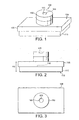
- Figures 1 to 4 illustrate such a digital camera module 100.
- Figure 1 is a perspective top view of the module
- Figure 2 is a front side view of the module
- Figure 3 is a top plan view of the module
- Figure 4 is a bottom plan view of the module.
- the module 100 comprises a substrate 110 and a lens structure 130.
- the substrate 110 may be a rectangular-shaped ceramic substrate comprising electronic circuitry including an image sensor 116 on a top surface, and metallic terminals 114 on a bottom surface 112 for electrically coupling the module 100 to external circuitry.
- the lens structure 130 comprises a rectangular-shaped base portion 135, and a turret portion 150 extending from the base portion 135.
- the base portion 135 and the turret portion 150 may both be formed of a plastics material.
- the turret portion 150 defines an aperture 160 through which light is received into the camera module for detection by the image sensor 116.
- a lens 170 is positioned within the aperture 160 for focusing received light onto the image sensor 116.
- a drawback with known digital camera modules is that they are difficult to connect to printed wiring boards (PWBs).
- PWBs printed wiring boards
- Reflow soldering of the ceramic substrate terminals 114 to a PWB is problematic as the plastics used in the lens 170 melt at temperatures less than the reflow temperatures. Reflow soldering may be possible if the lens is made from a glass material.
- glass lenses are expensive and are less suitable for mass production techniques.
- One method for connecting a digital camera module to a PWB involves using a flexible intermediate substrate.
- the flexible substrate is glued at one end to the bottom surface 112 of the ceramic substrate 110 with locally-conductive adhesive such that the substrate terminals 114 electrically couple to electrical traces in the flexible substrate.
- the other end of the flexible substrate is then connected to the PWB via a FPC connector. This method is labor intensive and does not lend itself to automated assembly easily.
- a connector for coupling a component to external circuitry comprising a base, a guide for guiding the component along an axis towards the base, a first barb positioned to latch an edge of the component at a first distance along the axis from the base, and a second barb positioned to latch an edge of the component at a second distance along the axis from the base.
- a connector in accordance with the invention has the advantage that it is able to receive components along one axis which in turn enables simple assembly of the component to the connector.
- a connector in accordance with the invention also has the advantage that it is able to receive components that have housings of different height due to the two barb arrangement. In other words, the two barb arrangement enables a component to be retained by an edge of the component even when the height of that edge varies.
- the component is preferably a digital camera module.
- the base includes electrical interconnects for coupling to the component/digital camera module.
- the guide comprises side walls extending from a planar base.
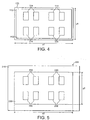
- Figure 5 is a plan view of a connector 200 in accordance with the invention.
- the connector is made of a plastics material and is shaped generally like box having an open top.
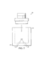
- the connector 200 is further illustrated in Figures 6 and 7 , which show a side view and an end view respectively.
- the connector 200 comprises a generally planar base portion 220 and four side walls 210 extending perpendicular to the base to form the open box shape.
- the connector 200 is designed to receive the camera module 100 of Figure 1 along the Z-axis.
- Eight electrical interconnects 230 made of metal such as copper are embedded into the base 220 such that each interconnect has a internal portion extending to the inside of the box, and a external portion extending to the outside of the box.
- the internal portions are designed to couple to the terminals 114 of the camera module once it has been fully inserted into the connector 200.
- the external portions are designed to be soldered to traces of a PWB (not shown) in order to provide electrical connections to external components.
- the connector 200 is preferably reflow soldered to the PWB before the camera module 100 is received into the connector. Other types of connection between the external portions and the PWB may also be used, such as pin and socket type connections.
- the internal portions of the interconnects may extend up the side walls 210 to couple with correspondingly positioned terminals on the camera module.
- the external dimensions x1 and y1 of the rectangular-shaped base portion 135 of the camera module 100 are slightly smaller than the internal dimensions x2 and y2 of the connector box opening defined by the side walls 210.
- the side walls 210 thus act as guides to guide the camera module 100 into the connector along the Z-axis.
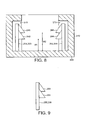
- Figure 8 illustrate the barbs that form part of the connector 200 to achieve this function.
- the barbs need not be exactly the pointed shape illustrated in the Figures so long as they function to hold the camera module at the desired position. Accordingly, the term barb is intended to encompasses more rounded shapes than those illustrated.
- Figures 8 and 12 to 17 illustrate an embodiment of the connector with four barbs 241, 242, 243, 244.
- An alternative embodiment of the connector with just two barbs is illustrated in Figures 9 to 11 .
- the barbs are supported by arms 251-254 that extend from the base 220 of the connector.
- the arms are coupled to the base 220 such that they can move independently of each other.
- Recesses 270 in the side walls 210 allow the arms and barbs to spring back as the camera module is received into the connector 200.
- the height of the camera module H3 (see Fig. 2 ) is known to have a large tolerance due to variations in the alignment of the lens structure 130 to the substrate 110.
- the use of barbs at different heights enables the connector 200 to receive and retain camera modules that vary greatly in height.
- the upper barb is positioned at a height H2 that is near the maximum tolerance for H3 while the lower barb is positioned at a height H1 that is near the minimum tolerance for H3.
- Figure 11 illustrates how the connector 200 according to the invention can retain a camera module 100 that has a large height H3 by means of the upper barb 261.
- the lower barb 262 is simply deflected out of the way.
- Figure 10 in contrast illustrates how the connector 200 according to the invention can retain a camera module that has a smaller height H3 by means of the lower barb 262.
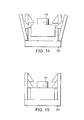
- Figures 12 to 15 illustrate the sequence of deflections of the four barbs 241-244 (originally shown in Figure 8 ) as a camera module 100 with a small height is received by the connector 200 along the vertical z-axis.
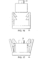
- Figures 16 and 17 illustrate a similar sequence for a camera module 100 with a larger height.
- Figures 15 and 17 illustrate the camera module 100 fully inserted and retained in the connector 200.
- further barbs may be added at heights other than H1 and H2 to accommodate further variations in the height H3 of the camera module, or to engage different edges of the camera module.
- Other components that may be retained by the connector include, for example, lamps, laser diodes etc.
Landscapes
- Studio Devices (AREA)
- Details Of Connecting Devices For Male And Female Coupling (AREA)
- Camera Bodies And Camera Details Or Accessories (AREA)
- Connecting Device With Holders (AREA)
- Solid State Image Pick-Up Elements (AREA)
- Coupling Device And Connection With Printed Circuit (AREA)
- Multi-Conductor Connections (AREA)
- Burglar Alarm Systems (AREA)
- Mechanical Coupling Of Light Guides (AREA)
- Surgical Instruments (AREA)
Applications Claiming Priority (3)
| Application Number | Priority Date | Filing Date | Title |
|---|---|---|---|
| GBGB0220751.2A GB0220751D0 (en) | 2002-09-06 | 2002-09-06 | A camera connector |
| GB0220751 | 2002-09-06 | ||
| PCT/GB2003/003851 WO2004023608A1 (en) | 2002-09-06 | 2003-09-08 | Connector |
Publications (2)
| Publication Number | Publication Date |
|---|---|
| EP1537633A1 EP1537633A1 (en) | 2005-06-08 |
| EP1537633B1 true EP1537633B1 (en) | 2011-11-23 |
Family
ID=9943624
Family Applications (1)
| Application Number | Title | Priority Date | Filing Date |
|---|---|---|---|
| EP03748252A Expired - Lifetime EP1537633B1 (en) | 2002-09-06 | 2003-09-08 | Connector |
Country Status (9)
| Country | Link |
|---|---|
| US (1) | US7101195B2 (enExample) |
| EP (1) | EP1537633B1 (enExample) |
| JP (2) | JP2005538503A (enExample) |
| KR (1) | KR100658192B1 (enExample) |
| CN (1) | CN100338828C (enExample) |
| AT (1) | ATE535042T1 (enExample) |
| AU (1) | AU2003267560A1 (enExample) |
| GB (1) | GB0220751D0 (enExample) |
| WO (1) | WO2004023608A1 (enExample) |
Families Citing this family (13)
| Publication number | Priority date | Publication date | Assignee | Title |
|---|---|---|---|---|
| DE102005018316B4 (de) * | 2005-04-20 | 2010-04-08 | Airbus Deutschland Gmbh | Modulares Installationskonzept für eine Kamera |
| US7520686B2 (en) | 2005-04-20 | 2009-04-21 | Airbus Deutschland Gmbh | Modular installation concept for a camera |
| JP4464878B2 (ja) * | 2005-07-11 | 2010-05-19 | 矢崎総業株式会社 | 電気接続箱 |
| DE202005014366U1 (de) * | 2005-09-12 | 2005-11-17 | Siemens Ag | Toleranzausgleich bei Steckverbindern durch mehrstufige Verrastung an einem dritten Bauteil |
| US8096594B2 (en) * | 2007-04-23 | 2012-01-17 | Adams Rite Manufacturing Co. | Compact electric strike with preload release capability |
| WO2008146812A1 (ja) * | 2007-05-29 | 2008-12-04 | Konica Minolta Opto, Inc. | 撮像装置の製造方法、撮像装置及び光学素子 |
| KR101393744B1 (ko) * | 2007-09-27 | 2014-05-12 | 엘지이노텍 주식회사 | 카메라 모듈 결합체, 카메라 모듈 및 소켓 |
| US20100213724A1 (en) * | 2009-02-26 | 2010-08-26 | Adam Rite Manufacturing Co. | Multiple point door locking system, with handle turning direction control |
| US9222286B2 (en) * | 2009-03-20 | 2015-12-29 | Hanchett Entry Systems, Inc. | Multiple point door locking system |
| US8882162B2 (en) | 2009-03-20 | 2014-11-11 | Hanchett Entry Systems, Inc. | Multiple point door locking system, with handle turning direction control |
| CN102074864B (zh) * | 2009-11-20 | 2013-01-16 | 群康科技(深圳)有限公司 | 插座及插座组件 |
| DE102015221581B4 (de) * | 2015-11-04 | 2017-12-14 | Magna Mirrors Holding Gmbh | Kameramodul |
| JP2018057124A (ja) * | 2016-09-28 | 2018-04-05 | 矢崎総業株式会社 | 電子部品保持構造、電気接続箱、及び、ワイヤハーネス |
Family Cites Families (14)
| Publication number | Priority date | Publication date | Assignee | Title |
|---|---|---|---|---|
| JPH0218950Y2 (enExample) * | 1985-12-16 | 1990-05-25 | ||
| JPS6364222A (ja) * | 1986-09-04 | 1988-03-22 | 松下電器産業株式会社 | スイツチの保持装置 |
| JPH0421270Y2 (enExample) * | 1987-03-16 | 1992-05-14 | ||
| JPH056696Y2 (enExample) * | 1987-07-15 | 1993-02-19 | ||
| US5302141A (en) * | 1992-11-23 | 1994-04-12 | Cole Hersee Company | Compatible trailer connection |
| JPH0662591U (ja) * | 1993-02-01 | 1994-09-02 | 富士電気化学株式会社 | プリント基板取付用スペーサ |
| JPH0745348A (ja) * | 1993-07-27 | 1995-02-14 | Matsushita Electric Works Ltd | リレーソケット |
| US6078756A (en) * | 1997-04-30 | 2000-06-20 | Eastman Kodak Company | Photographic and data transmission system for capturing images and magnetic data |
| JP2001188155A (ja) * | 1999-12-28 | 2001-07-10 | Kuurii Components Kk | 撮像素子の固定手段 |
| JP2001338944A (ja) * | 2000-03-24 | 2001-12-07 | Matsushita Electric Ind Co Ltd | 固定治具、固定治具付配線基板、及び電子部品実装体とその製造方法 |
| JP2002124312A (ja) * | 2000-10-13 | 2002-04-26 | Yazaki Corp | 補機モジュールおよびその製造方法 |
| JP2002158046A (ja) * | 2000-11-17 | 2002-05-31 | Yazaki Corp | 補機モジュール |
| TW460005U (en) * | 2000-12-30 | 2001-10-11 | Inventec Multimedia & Telecom | Expanding apparatus of digital camera |
| US6435882B1 (en) * | 2001-07-27 | 2002-08-20 | Agilent Technologies, Inc. | Socketable flexible circuit based electronic device module and a socket for the same |
-
2002
- 2002-09-06 GB GBGB0220751.2A patent/GB0220751D0/en not_active Ceased
-
2003
- 2003-09-08 AU AU2003267560A patent/AU2003267560A1/en not_active Abandoned
- 2003-09-08 KR KR1020057003868A patent/KR100658192B1/ko not_active Expired - Fee Related
- 2003-09-08 CN CNB038212404A patent/CN100338828C/zh not_active Expired - Fee Related
- 2003-09-08 AT AT03748252T patent/ATE535042T1/de active
- 2003-09-08 US US10/526,789 patent/US7101195B2/en not_active Expired - Lifetime
- 2003-09-08 WO PCT/GB2003/003851 patent/WO2004023608A1/en not_active Ceased
- 2003-09-08 JP JP2004533647A patent/JP2005538503A/ja active Pending
- 2003-09-08 EP EP03748252A patent/EP1537633B1/en not_active Expired - Lifetime
-
2010
- 2010-02-15 JP JP2010029695A patent/JP4855527B2/ja not_active Expired - Fee Related
Also Published As
| Publication number | Publication date |
|---|---|
| ATE535042T1 (de) | 2011-12-15 |
| KR100658192B1 (ko) | 2006-12-15 |
| US20060128202A1 (en) | 2006-06-15 |
| WO2004023608A1 (en) | 2004-03-18 |
| CN1682416A (zh) | 2005-10-12 |
| JP2010165682A (ja) | 2010-07-29 |
| US7101195B2 (en) | 2006-09-05 |
| CN100338828C (zh) | 2007-09-19 |
| AU2003267560A1 (en) | 2004-03-29 |
| EP1537633A1 (en) | 2005-06-08 |
| KR20050057233A (ko) | 2005-06-16 |
| JP2005538503A (ja) | 2005-12-15 |
| GB0220751D0 (en) | 2002-10-16 |
| JP4855527B2 (ja) | 2012-01-18 |
Similar Documents
| Publication | Publication Date | Title |
|---|---|---|
| JP4855527B2 (ja) | コネクタ | |
| EP2816677B1 (en) | Combined optical and electrical interface | |
| US7387517B2 (en) | Connector mounting structure | |
| US10454194B1 (en) | Card edge connector assembly | |
| JP3905518B2 (ja) | フローティング型コネクタ | |
| US7850466B2 (en) | Through board inverted connector | |
| KR20080012765A (ko) | 소형화에 용이하게 적응된 커넥터 | |
| JP2006210205A (ja) | モジュール用ソケット | |
| CN1099731C (zh) | 浮动式导向连接器及方法 | |
| CN212209927U (zh) | 插座以及ic封装 | |
| US5865413A (en) | Surface mountable component holder | |
| US20120044591A1 (en) | Camera module | |
| EP1803195B1 (en) | Socket for digital camera module | |
| CN217521425U (zh) | 驱动装置、摄像模组及电子设备 | |
| US7648288B2 (en) | Optical transmission device and electronic equipment with use thereof | |
| US7056133B2 (en) | Surface mounting connector | |
| US20080045050A1 (en) | Connector and portable electronic device using the same | |
| CN1115749C (zh) | 电连接器组合 | |
| US20030203672A1 (en) | Retainer bracket for connectors | |
| CN214544470U (zh) | 一种潜望式摄像模组及电子设备 | |
| US11888219B2 (en) | Antenna and assembly | |
| KR102633838B1 (ko) | 플로팅 커넥터 | |
| CN214505958U (zh) | Sfp连接器的信号辨识模组及其连接器 | |
| JP2006344418A (ja) | コネクタ、コネクタの嵌合方法、及び携帯端末 | |
| JPH04166807A (ja) | 光送/受信用モジュール |
Legal Events
| Date | Code | Title | Description |
|---|---|---|---|
| PUAI | Public reference made under article 153(3) epc to a published international application that has entered the european phase |
Free format text: ORIGINAL CODE: 0009012 |
|
| 17P | Request for examination filed |
Effective date: 20050404 |
|
| AK | Designated contracting states |
Kind code of ref document: A1 Designated state(s): AT BE BG CH CY CZ DE DK EE ES FI FR GB GR HU IE IT LI LU MC NL PT RO SE SI SK TR |
|
| AX | Request for extension of the european patent |
Extension state: AL LT LV MK |
|
| DAX | Request for extension of the european patent (deleted) | ||
| GRAP | Despatch of communication of intention to grant a patent |
Free format text: ORIGINAL CODE: EPIDOSNIGR1 |
|
| GRAS | Grant fee paid |
Free format text: ORIGINAL CODE: EPIDOSNIGR3 |
|
| GRAA | (expected) grant |
Free format text: ORIGINAL CODE: 0009210 |
|
| AK | Designated contracting states |
Kind code of ref document: B1 Designated state(s): AT BE BG CH CY CZ DE DK EE ES FI FR GB GR HU IE IT LI LU MC NL PT RO SE SI SK TR |
|
| REG | Reference to a national code |
Ref country code: GB Ref legal event code: FG4D |
|
| REG | Reference to a national code |
Ref country code: CH Ref legal event code: EP |
|
| REG | Reference to a national code |
Ref country code: IE Ref legal event code: FG4D |
|
| REG | Reference to a national code |
Ref country code: DE Ref legal event code: R081 Ref document number: 60339211 Country of ref document: DE Owner name: NOKIA TECHNOLOGIES OY, FI Free format text: FORMER OWNER: NOKIA CORP., 02610 ESPOO, FI |
|
| REG | Reference to a national code |
Ref country code: NL Ref legal event code: T3 |
|
| REG | Reference to a national code |
Ref country code: DE Ref legal event code: R096 Ref document number: 60339211 Country of ref document: DE Effective date: 20120223 |
|
| PG25 | Lapsed in a contracting state [announced via postgrant information from national office to epo] |
Ref country code: SI Free format text: LAPSE BECAUSE OF FAILURE TO SUBMIT A TRANSLATION OF THE DESCRIPTION OR TO PAY THE FEE WITHIN THE PRESCRIBED TIME-LIMIT Effective date: 20111123 Ref country code: PT Free format text: LAPSE BECAUSE OF FAILURE TO SUBMIT A TRANSLATION OF THE DESCRIPTION OR TO PAY THE FEE WITHIN THE PRESCRIBED TIME-LIMIT Effective date: 20120323 Ref country code: BE Free format text: LAPSE BECAUSE OF FAILURE TO SUBMIT A TRANSLATION OF THE DESCRIPTION OR TO PAY THE FEE WITHIN THE PRESCRIBED TIME-LIMIT Effective date: 20111123 Ref country code: SE Free format text: LAPSE BECAUSE OF FAILURE TO SUBMIT A TRANSLATION OF THE DESCRIPTION OR TO PAY THE FEE WITHIN THE PRESCRIBED TIME-LIMIT Effective date: 20111123 Ref country code: GR Free format text: LAPSE BECAUSE OF FAILURE TO SUBMIT A TRANSLATION OF THE DESCRIPTION OR TO PAY THE FEE WITHIN THE PRESCRIBED TIME-LIMIT Effective date: 20120224 |
|
| PG25 | Lapsed in a contracting state [announced via postgrant information from national office to epo] |
Ref country code: CY Free format text: LAPSE BECAUSE OF FAILURE TO SUBMIT A TRANSLATION OF THE DESCRIPTION OR TO PAY THE FEE WITHIN THE PRESCRIBED TIME-LIMIT Effective date: 20111123 |
|
| PG25 | Lapsed in a contracting state [announced via postgrant information from national office to epo] |
Ref country code: CZ Free format text: LAPSE BECAUSE OF FAILURE TO SUBMIT A TRANSLATION OF THE DESCRIPTION OR TO PAY THE FEE WITHIN THE PRESCRIBED TIME-LIMIT Effective date: 20111123 Ref country code: SK Free format text: LAPSE BECAUSE OF FAILURE TO SUBMIT A TRANSLATION OF THE DESCRIPTION OR TO PAY THE FEE WITHIN THE PRESCRIBED TIME-LIMIT Effective date: 20111123 Ref country code: DK Free format text: LAPSE BECAUSE OF FAILURE TO SUBMIT A TRANSLATION OF THE DESCRIPTION OR TO PAY THE FEE WITHIN THE PRESCRIBED TIME-LIMIT Effective date: 20111123 Ref country code: BG Free format text: LAPSE BECAUSE OF FAILURE TO SUBMIT A TRANSLATION OF THE DESCRIPTION OR TO PAY THE FEE WITHIN THE PRESCRIBED TIME-LIMIT Effective date: 20120223 Ref country code: EE Free format text: LAPSE BECAUSE OF FAILURE TO SUBMIT A TRANSLATION OF THE DESCRIPTION OR TO PAY THE FEE WITHIN THE PRESCRIBED TIME-LIMIT Effective date: 20111123 |
|
| PG25 | Lapsed in a contracting state [announced via postgrant information from national office to epo] |
Ref country code: IT Free format text: LAPSE BECAUSE OF FAILURE TO SUBMIT A TRANSLATION OF THE DESCRIPTION OR TO PAY THE FEE WITHIN THE PRESCRIBED TIME-LIMIT Effective date: 20111123 Ref country code: RO Free format text: LAPSE BECAUSE OF FAILURE TO SUBMIT A TRANSLATION OF THE DESCRIPTION OR TO PAY THE FEE WITHIN THE PRESCRIBED TIME-LIMIT Effective date: 20111123 |
|
| REG | Reference to a national code |
Ref country code: AT Ref legal event code: MK05 Ref document number: 535042 Country of ref document: AT Kind code of ref document: T Effective date: 20111123 |
|
| PLBE | No opposition filed within time limit |
Free format text: ORIGINAL CODE: 0009261 |
|
| STAA | Information on the status of an ep patent application or granted ep patent |
Free format text: STATUS: NO OPPOSITION FILED WITHIN TIME LIMIT |
|
| 26N | No opposition filed |
Effective date: 20120824 |
|
| REG | Reference to a national code |
Ref country code: DE Ref legal event code: R097 Ref document number: 60339211 Country of ref document: DE Effective date: 20120824 |
|
| PG25 | Lapsed in a contracting state [announced via postgrant information from national office to epo] |
Ref country code: AT Free format text: LAPSE BECAUSE OF FAILURE TO SUBMIT A TRANSLATION OF THE DESCRIPTION OR TO PAY THE FEE WITHIN THE PRESCRIBED TIME-LIMIT Effective date: 20111123 |
|
| PG25 | Lapsed in a contracting state [announced via postgrant information from national office to epo] |
Ref country code: ES Free format text: LAPSE BECAUSE OF FAILURE TO SUBMIT A TRANSLATION OF THE DESCRIPTION OR TO PAY THE FEE WITHIN THE PRESCRIBED TIME-LIMIT Effective date: 20120305 Ref country code: MC Free format text: LAPSE BECAUSE OF NON-PAYMENT OF DUE FEES Effective date: 20120930 |
|
| REG | Reference to a national code |
Ref country code: CH Ref legal event code: PL |
|
| GBPC | Gb: european patent ceased through non-payment of renewal fee |
Effective date: 20120908 |
|
| REG | Reference to a national code |
Ref country code: IE Ref legal event code: MM4A |
|
| PG25 | Lapsed in a contracting state [announced via postgrant information from national office to epo] |
Ref country code: FI Free format text: LAPSE BECAUSE OF FAILURE TO SUBMIT A TRANSLATION OF THE DESCRIPTION OR TO PAY THE FEE WITHIN THE PRESCRIBED TIME-LIMIT Effective date: 20111123 |
|
| REG | Reference to a national code |
Ref country code: FR Ref legal event code: ST Effective date: 20130531 |
|
| PG25 | Lapsed in a contracting state [announced via postgrant information from national office to epo] |
Ref country code: CH Free format text: LAPSE BECAUSE OF NON-PAYMENT OF DUE FEES Effective date: 20120930 Ref country code: IE Free format text: LAPSE BECAUSE OF NON-PAYMENT OF DUE FEES Effective date: 20120908 Ref country code: LI Free format text: LAPSE BECAUSE OF NON-PAYMENT OF DUE FEES Effective date: 20120930 Ref country code: GB Free format text: LAPSE BECAUSE OF NON-PAYMENT OF DUE FEES Effective date: 20120908 |
|
| PG25 | Lapsed in a contracting state [announced via postgrant information from national office to epo] |
Ref country code: FR Free format text: LAPSE BECAUSE OF NON-PAYMENT OF DUE FEES Effective date: 20121001 |
|
| PG25 | Lapsed in a contracting state [announced via postgrant information from national office to epo] |
Ref country code: TR Free format text: LAPSE BECAUSE OF FAILURE TO SUBMIT A TRANSLATION OF THE DESCRIPTION OR TO PAY THE FEE WITHIN THE PRESCRIBED TIME-LIMIT Effective date: 20111123 |
|
| PG25 | Lapsed in a contracting state [announced via postgrant information from national office to epo] |
Ref country code: LU Free format text: LAPSE BECAUSE OF NON-PAYMENT OF DUE FEES Effective date: 20120908 |
|
| PG25 | Lapsed in a contracting state [announced via postgrant information from national office to epo] |
Ref country code: HU Free format text: LAPSE BECAUSE OF FAILURE TO SUBMIT A TRANSLATION OF THE DESCRIPTION OR TO PAY THE FEE WITHIN THE PRESCRIBED TIME-LIMIT Effective date: 20030908 |
|
| REG | Reference to a national code |
Ref country code: DE Ref legal event code: R081 Ref document number: 60339211 Country of ref document: DE Owner name: NOKIA TECHNOLOGIES OY, FI Free format text: FORMER OWNER: NOKIA CORPORATION, ESPOO, FI Ref country code: DE Ref legal event code: R081 Ref document number: 60339211 Country of ref document: DE Owner name: NOKIA TECHNOLOGIES OY, FI Free format text: FORMER OWNER: NOKIA CORPORATION, 02610 ESPOO, FI |
|
| REG | Reference to a national code |
Ref country code: NL Ref legal event code: PD Owner name: NOKIA TECHNOLOGIES OY; FI Free format text: DETAILS ASSIGNMENT: VERANDERING VAN EIGENAAR(S), OVERDRACHT; FORMER OWNER NAME: NOKIA CORPORATION Effective date: 20151111 |
|
| PGFP | Annual fee paid to national office [announced via postgrant information from national office to epo] |
Ref country code: NL Payment date: 20210915 Year of fee payment: 19 |
|
| PGFP | Annual fee paid to national office [announced via postgrant information from national office to epo] |
Ref country code: DE Payment date: 20210803 Year of fee payment: 19 |
|
| REG | Reference to a national code |
Ref country code: DE Ref legal event code: R119 Ref document number: 60339211 Country of ref document: DE |
|
| REG | Reference to a national code |
Ref country code: NL Ref legal event code: MM Effective date: 20221001 |
|
| PG25 | Lapsed in a contracting state [announced via postgrant information from national office to epo] |
Ref country code: NL Free format text: LAPSE BECAUSE OF NON-PAYMENT OF DUE FEES Effective date: 20221001 |
|
| PG25 | Lapsed in a contracting state [announced via postgrant information from national office to epo] |
Ref country code: DE Free format text: LAPSE BECAUSE OF NON-PAYMENT OF DUE FEES Effective date: 20230401 |