EP1535877B1 - Teleskopausleger - Google Patents
Teleskopausleger Download PDFInfo
- Publication number
- EP1535877B1 EP1535877B1 EP04106067.4A EP04106067A EP1535877B1 EP 1535877 B1 EP1535877 B1 EP 1535877B1 EP 04106067 A EP04106067 A EP 04106067A EP 1535877 B1 EP1535877 B1 EP 1535877B1
- Authority
- EP
- European Patent Office
- Prior art keywords
- section
- boom arm
- arm
- sections
- flexible
- Prior art date
- Legal status (The legal status is an assumption and is not a legal conclusion. Google has not performed a legal analysis and makes no representation as to the accuracy of the status listed.)
- Expired - Lifetime
Links
- 238000005192 partition Methods 0.000 claims description 3
- 238000003466 welding Methods 0.000 claims description 3
- 230000003247 decreasing effect Effects 0.000 claims description 2
- 239000012530 fluid Substances 0.000 description 10
- 238000005452 bending Methods 0.000 description 1
- 239000000463 material Substances 0.000 description 1
- 230000000116 mitigating effect Effects 0.000 description 1
- 230000000717 retained effect Effects 0.000 description 1
Images


Classifications
-
- B—PERFORMING OPERATIONS; TRANSPORTING
- B66—HOISTING; LIFTING; HAULING
- B66C—CRANES; LOAD-ENGAGING ELEMENTS OR DEVICES FOR CRANES, CAPSTANS, WINCHES, OR TACKLES
- B66C23/00—Cranes comprising essentially a beam, boom, or triangular structure acting as a cantilever and mounted for translatory of swinging movements in vertical or horizontal planes or a combination of such movements, e.g. jib-cranes, derricks, tower cranes
- B66C23/62—Constructional features or details
- B66C23/64—Jibs
- B66C23/70—Jibs constructed of sections adapted to be assembled to form jibs or various lengths
- B66C23/701—Jibs constructed of sections adapted to be assembled to form jibs or various lengths telescopic
-
- B—PERFORMING OPERATIONS; TRANSPORTING
- B66—HOISTING; LIFTING; HAULING
- B66C—CRANES; LOAD-ENGAGING ELEMENTS OR DEVICES FOR CRANES, CAPSTANS, WINCHES, OR TACKLES
- B66C13/00—Other constructional features or details
- B66C13/12—Arrangements of means for transmitting pneumatic, hydraulic, or electric power to movable parts of devices
- B66C13/14—Arrangements of means for transmitting pneumatic, hydraulic, or electric power to movable parts of devices to load-engaging elements or motors associated therewith
-
- B—PERFORMING OPERATIONS; TRANSPORTING
- B66—HOISTING; LIFTING; HAULING
- B66F—HOISTING, LIFTING, HAULING OR PUSHING, NOT OTHERWISE PROVIDED FOR, e.g. DEVICES WHICH APPLY A LIFTING OR PUSHING FORCE DIRECTLY TO THE SURFACE OF A LOAD
- B66F9/00—Devices for lifting or lowering bulky or heavy goods for loading or unloading purposes
- B66F9/06—Devices for lifting or lowering bulky or heavy goods for loading or unloading purposes movable, with their loads, on wheels or the like, e.g. fork-lift trucks
- B66F9/065—Devices for lifting or lowering bulky or heavy goods for loading or unloading purposes movable, with their loads, on wheels or the like, e.g. fork-lift trucks non-masted
- B66F9/0655—Devices for lifting or lowering bulky or heavy goods for loading or unloading purposes movable, with their loads, on wheels or the like, e.g. fork-lift trucks non-masted with a telescopic boom
Definitions
- the present invention relates to a telescopic boom arm and is particularly concerned with the routing of flexible hydraulic lines in the boom arm.
- a hydraulically operated telescopically collapsible boom arm on a self-propelled low profile material handling vehicle, such a vehicle being commonly referred to as a telehandler.
- the boom arm extends lengthways of the vehicle and is mounted to one side of the centreline of the vehicle, the cab being positioned on the opposite side.
- the boom arm is transported in a horizontal position, enabling the driver sitting in the cab to look over it.
- the boom arm is pivoted to the body of the vehicle so that it can be raised from its transport position to a near-vertical position by means of a hydraulic cylinder acting between the first section of the boom arm and the vehicle body.
- the boom arm has several hollow sections of progressively smaller cross section which are located one within the other when the boom arm is retracted to its minimum length.
- the sections can be moved apart to extend the boom arm by means of hydraulic cylinders arranged within the boom arm.
- the free end of the boom arm can carry a variety of implements or devices, for example a fork assembly as described in US-RE. 30,021 , that may themselves also be hydraulically powered.
- FR 2,648,122 discloses a telescoping boom according to the preamble claim 1 with four sections. Two hydraulic cylinders are mounted at the inside of the third section one for extending section four with respect to section three, the other for extending section three with respect to section two. This last cylinder is fed by a flexible hydraulic hose running via a U-turn to its rod side, which is connected to section two, and being partially covered by the first and second section. When extending the boom its U-turn moves at half the speed of the movement of the second section largely uncovering the flexible hoses.
- the present invention provides a telescopic boom arm comprising a plurality of elongate sections of progressively decreasing cross section received and guided one within the other, wherein a flexible hydraulic line is connected to one of the inner sections of the boom arm and an elongate channel is defined between two of the sections of the boom arm to accommodate the flexible hydraulic line when the boom arm is in its fully retracted condition.
- the sections will herein be identified by their position along the extended boom arm, the first section being the one pivoted on the vehicle, the second being the next smaller section and so on. To distinguish them from one another, the ends of the different sections of the boom arm will herein be referred to as the rear end and the front end, respectively.
- the rear end of a section is the one nearer the end of the boom arm pivoted on the vehicle and the front end is the one nearer the free end of the boom arm.
- the invention can be applied to a boom arm having three or four sections.
- the boom arm has four sections, it is preferable to mount two hydraulic double acting cylinders on the third section one having a piston rod connected to the second section and the other having a piston rod connected to the fourth section, the second section being moved relative to the first by means of a double acting cylinder located outside the boom arm.
- the boom arm has fewer than four sections, it is possible to dispense with the external hydraulic cylinder, whereupon two cylinders may be mounted on the second section with their piston rods connected to the first and third sections, respectively.
- the channel to accommodate the flexible hydraulic lines leading to the moving cylinders is conveniently located between the outer wall of the second section and the inner wall of the first section.
- a space between the first and second sections of the boom arm is divided by partitions into separate channels each only wide enough to receive one pair of flexible hydraulic lines.
- each flexible hydraulic line that moves when the boom arm is extended or retracted will always comprise runs separated by a U-bend regardless of the degree of extension of the boom arm. All that happens when the sections of the boom arm move relative to one another is that the ratio of the length of the two runs will change. In other words, the U-bend will move with the moving section (but at half its rate) and one run will become longer as the other becomes shorter.
- the flexible line is merely unfurled from the channel and it is not dragged relative to the inner wall of any of the sections.
- section of the boom arm carrying the cylinders to carry rigid tubes each connected at its rear end to a flexible hydraulic line accommodated in a channel defined between the first and second sections of the boom arm and at its front end to a flexible line leading to the free end of the boom arm to power an implement or device carried by the boom arm.
- the flexible line connected to the front end of each rigid tube may once again suitably have two runs separated by a U-bend accommodated within the last section of the boom arm, that is to say the smallest section at the free end of the boom arm.
- one of the two runs of each of the hydraulic lines leading to the free end of the boom is preferably stored within a closed channel defined by the last section of the boom arm.
- Such a channel may conveniently be formed by welding a strip of L-shaped cross section inside the corner of the last section.
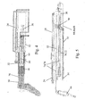
- the boom arm 10 shown in the drawings is formed of four telescoped sections or segments designated 12, 14, 16 and 18 respectively.
- the largest of the sections 12, which is herein termed the first section has at its rear end a pivot pin 20 by means of which it is pivotably mounted on a vehicle (not shown).
- the first section 12 On its underside, the first section 12 has a bracket 22 for connection to a hydraulic cylinder (not shown) that acts between the body of the vehicle and the first section 12, to raise and lower the boom arm 10 by pivoting it about the pin 20.
- a cylinder 24 is mounted above the first section 12 and its piston rod is connected by a pin 26 to the second section 14. The cylinder 24 is used to move the second section 14 of the boom arm 10 relative to the first section 12.
- two further cylinders 30 and 32 are connected for movement with the third section 16.
- the cylinders 30 and 32 are within the fourth section 18.
- the end of the piston rod 36 of the cylinder 30 is connected to the second section 14, whereas the piston rod 38 of the cylinder 32 is connected to the fourth section 18.
- the cylinders 24, 30 and 32 are all double acting and their working chambers are all connected in series, as shown in Figure 4 , so that all sections of the boom arm 10 move in unison. In order that the sections should move relative to one another by equal amounts, the areas of the working chambers are progressively reduced to compensate for the diameters of the various piston rods.
- a pump (not shown) draws hydraulic fluid from a reservoir and supplies it to the chamber to the right of the piston of the cylinder 24, as viewed. This causes the piston rod of the cylinder 24 to move to the left and thereby extend the second section 14.
- the hydraulic fluid from the second working chamber of the cylinder 24 flows to the first working chamber of the cylinder 32 and extends the fourth section 18 relative to the third section 16.
- the fluid from the second working chamber of the cylinder 32 flows through an internal connection to the first working chamber of the cylinder 30 and extends the third section 16 relative to the second section 14.
- the fluid discharged from the second working chamber of the cylinder 30 is returned to the reservoir from which fluid is drawn by the pump.
- the pump and reservoir are connected to the cylinders 24 and 30 through a cross-over valve (not shown) allowing the pump to supply fluid to the cylinder 30 in order to retract the boom arm 10.
- the free end of the boom arm 10 carries an implement which may be a lifting fork.
- the non-illustrated implement may also for example be a bucket or shovel that is mounted on an arm 40 pivotable relative to the boom arm 10 about a pivot pin 42.
- the actuator for the implement is a further tilt cylinder 44 to which hydraulic fluid needs to be supplied.
- auxiliary hydraulic lines may be required to operate a device at the free end of the boom arm.
- a hydraulically operated load lock device may be provided to lock the load to safeguard against failure of the hydraulic lines leading to the tilt cylinder. All these flexible lines have hitherto either been located outside the boom arm or else they have been guided to run up the centre of the boom arm.
- the hydraulic lines leading to and from the cylinders 30 and 32 as well as the lines of the tilt cylinder 44 and the auxiliary lines, are all contained within the boom arm 10.
- a first flexible hydraulic line is connected directly to the cylinder 24.
- the fluid from the other end of the cylinder 24 flows through a rigid external pipe 25 back to a connecting block at the rear end of the first section and from there the fluid is supplied by either a flexible or a rigid line to one of the connectors 50.
- the other five flexible lines connected to the connectors 50 are the return line from the cylinders 30 and 32, the two lines leading to the tilt cylinder 44 and the two auxiliary lines.
- the first section 12 is made significantly larger than the second section 14 to leave a space between the two beneath the second section 14 which is divided by upright partition walls 60 and 62 into three separate longitudinal channels.
- the pairs of flexible hydraulic lines 64, 66 and 68 are coupled to the connectors 54 and these pass each along a respective one of the three channels to the rear end of the third section 16.
- the paired hydraulic lines 64, 66 and 68 are joined to one another over most of their length and each channel is wide enough to accommodate only one pair of hydraulic lines. The flexible lines therefore simply rest as straight runs in these channels.
- the lines 68 after making a U-turn at the rear end of the boom arm, are connected to the hydraulic cylinders 30 and 32.
- the end of the lines 68 moves with the third section 16 and the U-bend moves at half the rate of the third section 16, in other words at the rate of the second section 14.
- the run of the lines 68 in the channel is always covered from above by the second section 14, which closes the channel. There is therefore no possibility of the lines 68 coming out of their channel.
- the lines 68 As the sections of the boom arm move relative to one another, the lines 68 always lie as two runs separated by a U-bend with one run encased in a channel and the other located inside the second section 14. As the sections move relative to another the U-bend moves to shorten one of the runs and lengthen the other.
- the other two pairs of flexible lines 64 and 66 are unfurled from their channels in the same way but at their other ends they are connected to two rigid pairs of pipes 70 and 72 that are mounted beneath the cylinders 30 and 32 for movement with the third section 16 of the boom arm. This brings the hydraulic connections required by the lines of the tilt cylinder 44 and the auxiliary lines to the front end of the third section 16 of the boom arm.
- each of the pairs of flexible lines 74, 76 is housed in a closed channel in an upper corner of the fourth section, the channel being formed by welding a strip 78 of L-shaped cross section within the corner of the section 18. There is therefore only one run of each pair that is capable of bending and this one run once again moves in the same way as the flexible lines 64, 66 and 68.
- the free runs of the pairs of flexible lines 74, 76 are confined laterally between the cylinders 30, 32 and the sides of the fourth section 18 and this once again constrains the movement of the flexible lines preventing them from becoming entangled.
- a boom arm with three sections can be constructed in the same manner as the second, third and fourth sections described above, with the omission of the first section and the external cylinder 24.
- the external cylinder 24 may be retained and only one cylinder needs then be mounted on the second of the sections to extend the third section.
Landscapes
- Engineering & Computer Science (AREA)
- Mechanical Engineering (AREA)
- Transportation (AREA)
- Structural Engineering (AREA)
- Civil Engineering (AREA)
- Life Sciences & Earth Sciences (AREA)
- Geology (AREA)
- Forklifts And Lifting Vehicles (AREA)
- Jib Cranes (AREA)
Claims (10)
- Ein Teleskop-Auslegerarm (10) mit:- einer Anzahl von langgestreckten Sektionen (12, 14, 16, 18) mit fortschreitend abnehmenden Querschnitt, die jeweils voneinander und ineinander aufgenommen und geführt werden;dadurch gekennzeichnet, dass die flexible Leitung (64, 66, 68) von dem einen Ende des U-Bogens von einer vollständig eingezogenen bis zu einer vollständig ausgefahrenen Position des Arms (10) im Wesentlichen vollständig durch einen langgestreckten Kanal abgedeckt ist, der durch die Innenseite der ersten Sektion (12) und die Außenseite einer zweiten größeren inneren Sektion (14, 16) gebildet ist, .
einer flexiblen Hydraulikleitung (64, 66, 68), die an einem Ende mit einem Verbindungsstück (54) verbunden ist, das an dem vorderen Ende einer ersten äußeren Sektion (12) angeordnet ist und die an ihrem anderen Ende mit einer kleineren inneren Sektion (16, 18) über einen U-Bogen durch die Hinterseite der kleineren inneren Sektionen (14, 16, 18) hindurch angeschlossen ist; - Ein Teleskoparm (10) nach Anspruch 1, dadurch gekennzeichnet, dass der langgestreckte Kanal durch Unterteilungen (60, 62) in getrennte Kanäle unterteilt ist, die lediglich breit genug sind, um ein Paar von flexiblen Hydraulikleitungen (64, 66, 68) aufzunehmen.
- Ein Teleskoparm (10) nach Anspruch 1 oder 2, bei dem die Hydraulikleitung (64, 66, 68) an dem anderen Ende mit einem oder mehreren doppelwirkenden Zylindern (30, 32) verbunden ist, die mit der Innenseite der kleineren inneren Sektion (16) verbunden sind.
- Ein Auslegerarm nach Anspruch 1 oder 2, dadurch gekennzeichnet, dass der Auslegerarm (10) vier Sektionen (12, 14, 16, 18) und zwei hydraulische doppelwirkende Zylinder (30, 32) aufweist, die die auf der dritten Sektion (16) befestigt sind, wobei ein Zylinder (30) eine Kolbenstange (36) aufweist, die mit der zweiten Sektion (14) verbunden ist, und der andere Zylinder (32) eine Kolbenstange (38) aufweist, die mit der vierten Sektion (18) verbunden ist, wobei die zweite Sektion (14) gegenüber der ersten Sektion (12) mit Hilfe eines doppelwirkenden Zylinders (24) bewegt wird, der außerhalb des Auslegerarms (10) angeordnet ist.
- Ein Auslegerarm nach Anspruch 1 oder 2, dadurch gekennzeichnet, dass der Auslegerarm (10) drei Sektionen aufweist, das ein doppelwirkender Zylinder auf der zweiten Sektion zum Ausfahren der dritten Sektion gegenüber der zweiten Sektion befestigt ist, und dass ein zweiter doppelwirkender Zylinder entweder außerhalb oder innerhalb des Auslegerarms (10) befestigt ist, um die zweite Sektion gegenüber der ersten Sektion auszufahren.
- Ein Teleskoparm (10) nach einem der vorhergehenden Ansprüche, bei dem ein weiterer Zylinder (24) betreibbar ist, um die zweite Sektion (14) gegenüber der ersten Sektion (12) zu bewegen.
- Ein Teleskoparm (10) nach einem der vorhergehenden Ansprüche, bei dem die dritte Sektion (16) zusätzlich starre Rohre (70, 72) trägt, die jeweils an ihrem hinteren Ende mit einer flexiblen Hydraulikleitung (64, 66), die in einem Kanal aufgenommen ist, der zwischen den ersten und zweiten Sektionen (12, 14) des Auslegerarms (10) begrenzt ist, und an ihrem vorderen Ende mit einer flexiblen Leitung (74, 76) verbunden sind, die zu dem freien Ende des Auslegerarms (10) führt, um ein Arbeitsgerät oder Bauteil anzutreiben, das von dem Auslegerarm (10) getragen wird.
- Ein Teleskoparm (10) nach Anspruch 7, bei dem die flexible Leitung (74, 76), die mit dem vorderen Ende jedes starren Rohres (70, 72) verbunden ist, zwei Stränge umfasst, die durch einen U-Bogen getrennt sind, der in der letzten Sektion (18) des Auslegerarms (10) untergebracht ist.
- Ein Teleskoparm (10) nach Anspruch 7 oder 8, bei dem einer der zwei Stränge jeder der Hydraulikleitungen (74, 76), die zu dem freien Ende des Auslegerarms (10) führen, in einen geschlossenen Kanal verstaut ist, der durch die letzte Sektion (18) des Auslegerarms gebildet ist.
- Ein Teleskoparm (10) nach Anspruch 9, bei dem der Kanal in der letzten Sektion (18) des Auslegerarms (10) durch Schweißen eines Streifens (78) mit einem L-förmigen Querschnitt im Inneren der Ecke der Sektion (18) gebildet ist.
Applications Claiming Priority (2)
| Application Number | Priority Date | Filing Date | Title |
|---|---|---|---|
| IT000957A ITTO20030957A1 (it) | 2003-11-28 | 2003-11-28 | Braccio sollevatore telescopico. |
| ITTO20030957 | 2003-11-28 |
Publications (2)
| Publication Number | Publication Date |
|---|---|
| EP1535877A1 EP1535877A1 (de) | 2005-06-01 |
| EP1535877B1 true EP1535877B1 (de) | 2015-07-29 |
Family
ID=34452295
Family Applications (1)
| Application Number | Title | Priority Date | Filing Date |
|---|---|---|---|
| EP04106067.4A Expired - Lifetime EP1535877B1 (de) | 2003-11-28 | 2004-11-25 | Teleskopausleger |
Country Status (3)
| Country | Link |
|---|---|
| US (1) | US7360662B2 (de) |
| EP (1) | EP1535877B1 (de) |
| IT (1) | ITTO20030957A1 (de) |
Families Citing this family (8)
| Publication number | Priority date | Publication date | Assignee | Title |
|---|---|---|---|---|
| JP5159796B2 (ja) * | 2008-01-07 | 2013-03-13 | 日本車輌製造株式会社 | 杭打機 |
| AT12942U1 (de) * | 2011-11-08 | 2013-02-15 | Palfinger Ag | Kran, insbesondere ladekran für ein fahrzeug |
| US10611618B2 (en) * | 2015-03-27 | 2020-04-07 | Chang Zhou Current Supply Company Of Jiangsu Electric Power Company | Amplitude limiting system of insulated aerial work platform |
| CN106395697B (zh) * | 2016-08-24 | 2019-10-01 | 浙江鼎力机械股份有限公司 | 伸缩连接组件及高空作业平台 |
| US10091922B2 (en) * | 2016-09-07 | 2018-10-09 | Cnh Industrial America Llc | Agricultural implement sliding hitch |
| KR102000781B1 (ko) * | 2017-12-08 | 2019-07-17 | 주식회사 진우에스엠씨 | 붐 인출 인입 장치 |
| IT201800004537A1 (it) * | 2018-04-16 | 2019-10-16 | Piattaforma aerea | |
| EP3650394B1 (de) * | 2018-11-06 | 2021-06-30 | Hiab AB | Haltevorrichtung für lastenhandhabungswerkzeug und hydraulischer kran mit solch einer haltevorrichtung |
Family Cites Families (16)
| Publication number | Priority date | Publication date | Assignee | Title |
|---|---|---|---|---|
| US3214033A (en) * | 1962-07-05 | 1965-10-26 | Hydrauliska Ind Aktiebolaget | Hydraulic line configuration for extensible members |
| DE1962945C3 (de) * | 1969-12-16 | 1974-04-04 | O & K Orenstein & Koppel Ag, 1000 Berlin | Langhubiger Hydraulikantrieb für einen Kran |
| US3623501A (en) * | 1970-07-13 | 1971-11-30 | Chance Co Ab | Continuous hydraulic hose structure for telescopic boom assembly |
| US3666125A (en) * | 1970-09-10 | 1972-05-30 | Warner Swasey Co | Boom assembly |
| US3804262A (en) * | 1972-09-18 | 1974-04-16 | Harnischfeger Corp | Telescopic boom |
| US3836025A (en) | 1973-05-21 | 1974-09-17 | Loed Corp | Material-handling machine |
| US4125974A (en) * | 1977-07-08 | 1978-11-21 | Harnischfeger Corporation | Control system for telescopic boom |
| US4380244A (en) * | 1981-03-05 | 1983-04-19 | Fmc Corporation | Hose control system |
| US4506480A (en) * | 1983-03-10 | 1985-03-26 | Calavar Corporation | Extensible boom construction for self-propelled aerial work platforms |
| US4954041A (en) * | 1987-10-21 | 1990-09-04 | Lull Corp. | Triple section telescopic boom materials handling vehicle |
| FR2648122B1 (fr) | 1989-06-09 | 1991-10-11 | Manitou Costruzioni Ind | Dispositif de bras telescopique pour chariot elevateur |
| GB2263270B (en) * | 1992-01-20 | 1995-01-11 | D J Ind Ltd | Load handling apparatus |
| CA2157340C (en) * | 1994-09-27 | 1998-06-09 | Donald C. Hade, Jr. | Carrier track system for independent and/or synchronized operation of a multi-section telescopic boom structure |
| DE19613700A1 (de) * | 1996-03-29 | 1997-10-02 | M E P Gmbh Ges Fuer Consulting | Teleskopartig auseinanderfahrbarer Maschinenteil |
| US6244450B1 (en) * | 1999-10-13 | 2001-06-12 | Elliott Equipment Company | Method and apparatus for telescoping boom with hydraulic extension actuators |
| DE10032585A1 (de) * | 2000-07-05 | 2002-01-17 | Deere & Co | Anbaurahmen und teleskopartiger Ausleger mit Anbaurahmen |
-
2003
- 2003-11-28 IT IT000957A patent/ITTO20030957A1/it unknown
-
2004
- 2004-11-25 EP EP04106067.4A patent/EP1535877B1/de not_active Expired - Lifetime
- 2004-11-29 US US10/999,081 patent/US7360662B2/en not_active Expired - Lifetime
Also Published As
| Publication number | Publication date |
|---|---|
| US7360662B2 (en) | 2008-04-22 |
| ITTO20030957A1 (it) | 2005-05-29 |
| US20050218101A1 (en) | 2005-10-06 |
| EP1535877A1 (de) | 2005-06-01 |
Similar Documents
| Publication | Publication Date | Title |
|---|---|---|
| AU678728B2 (en) | Carrier track system for independent and/or synchronized operation of a multi-section telescopic boom structures | |
| CN107021424B (zh) | 用于自推进的工作机器的伸缩臂 | |
| KR101802889B1 (ko) | 심굴 굴삭기 | |
| US20070295497A1 (en) | Articulated mast for a coiled tubing rig | |
| US7360662B2 (en) | Telescopic boom arm | |
| JP2018030716A (ja) | 伸縮式接続機構及び高所作業車 | |
| US7594679B1 (en) | Outrigger for a boom truck or the like | |
| US20130055658A1 (en) | Telescopic crane arm | |
| US5176491A (en) | Overcenter backhoe apparatus | |
| JPWO2004083099A1 (ja) | 自走式作業機械 | |
| US10982412B2 (en) | Hydraulic system for working machine and the working machine | |
| JP4201122B2 (ja) | リーチ式フォークリフト | |
| US7044705B2 (en) | Load handling machine | |
| CN215309884U (zh) | 曲臂云梯及云梯消防车 | |
| JP2000345582A (ja) | 作業装置 | |
| US6805038B2 (en) | Hydraulic cylinder pivot pin | |
| JP4174309B2 (ja) | 伸縮ブーム | |
| US3471034A (en) | Boom in a truck-crane | |
| JP3595652B2 (ja) | ブームの伸縮構造 | |
| JPH0581512U (ja) | バルブ内蔵型シリンダ | |
| JPS6026066Y2 (ja) | 移動式クレ−ンの油圧伸縮ブ−ム | |
| US3256779A (en) | Extensible boom | |
| JP2001019352A (ja) | 伸縮ブーム | |
| JPH08209736A (ja) | バックホウ | |
| JPS5836133B2 (ja) | バックホウ構体 |
Legal Events
| Date | Code | Title | Description |
|---|---|---|---|
| PUAI | Public reference made under article 153(3) epc to a published international application that has entered the european phase |
Free format text: ORIGINAL CODE: 0009012 |
|
| AK | Designated contracting states |
Kind code of ref document: A1 Designated state(s): AT BE BG CH CY CZ DE DK EE ES FI FR GB GR HU IE IS IT LI LU MC NL PL PT RO SE SI SK TR |
|
| AX | Request for extension of the european patent |
Extension state: AL HR LT LV MK YU |
|
| 17P | Request for examination filed |
Effective date: 20051114 |
|
| AKX | Designation fees paid |
Designated state(s): AT BE BG CH CY CZ DE DK EE ES FI FR GB GR HU IE IS IT LI LU MC NL PL PT RO SE SI SK TR |
|
| 17Q | First examination report despatched |
Effective date: 20101119 |
|
| RAP1 | Party data changed (applicant data changed or rights of an application transferred) |
Owner name: CNH ITALIA S.P.A. |
|
| RAP1 | Party data changed (applicant data changed or rights of an application transferred) |
Owner name: CNH ITALIA S.P.A. |
|
| RAP1 | Party data changed (applicant data changed or rights of an application transferred) |
Owner name: CNH INDUSTRIAL ITALIA S.P.A. |
|
| REG | Reference to a national code |
Ref country code: DE Ref legal event code: R079 Ref document number: 602004047560 Country of ref document: DE Free format text: PREVIOUS MAIN CLASS: B66C0013120000 Ipc: B66C0023690000 |
|
| GRAP | Despatch of communication of intention to grant a patent |
Free format text: ORIGINAL CODE: EPIDOSNIGR1 |
|
| RIC1 | Information provided on ipc code assigned before grant |
Ipc: B66F 9/065 20060101ALI20150209BHEP Ipc: B66C 13/14 20060101ALI20150209BHEP Ipc: B66C 23/69 20060101AFI20150209BHEP |
|
| INTG | Intention to grant announced |
Effective date: 20150224 |
|
| GRAS | Grant fee paid |
Free format text: ORIGINAL CODE: EPIDOSNIGR3 |
|
| GRAA | (expected) grant |
Free format text: ORIGINAL CODE: 0009210 |
|
| AK | Designated contracting states |
Kind code of ref document: B1 Designated state(s): AT BE BG CH CY CZ DE DK EE ES FI FR GB GR HU IE IS IT LI LU MC NL PL PT RO SE SI SK TR |
|
| REG | Reference to a national code |
Ref country code: GB Ref legal event code: FG4D |
|
| REG | Reference to a national code |
Ref country code: CH Ref legal event code: EP |
|
| REG | Reference to a national code |
Ref country code: AT Ref legal event code: REF Ref document number: 739107 Country of ref document: AT Kind code of ref document: T Effective date: 20150815 |
|
| REG | Reference to a national code |
Ref country code: IE Ref legal event code: FG4D |
|
| REG | Reference to a national code |
Ref country code: DE Ref legal event code: R096 Ref document number: 602004047560 Country of ref document: DE |
|
| REG | Reference to a national code |
Ref country code: FR Ref legal event code: PLFP Year of fee payment: 12 |
|
| REG | Reference to a national code |
Ref country code: AT Ref legal event code: MK05 Ref document number: 739107 Country of ref document: AT Kind code of ref document: T Effective date: 20150729 |
|
| REG | Reference to a national code |
Ref country code: NL Ref legal event code: MP Effective date: 20150729 |
|
| PG25 | Lapsed in a contracting state [announced via postgrant information from national office to epo] |
Ref country code: GR Free format text: LAPSE BECAUSE OF FAILURE TO SUBMIT A TRANSLATION OF THE DESCRIPTION OR TO PAY THE FEE WITHIN THE PRESCRIBED TIME-LIMIT Effective date: 20151030 Ref country code: FI Free format text: LAPSE BECAUSE OF FAILURE TO SUBMIT A TRANSLATION OF THE DESCRIPTION OR TO PAY THE FEE WITHIN THE PRESCRIBED TIME-LIMIT Effective date: 20150729 |
|
| PG25 | Lapsed in a contracting state [announced via postgrant information from national office to epo] |
Ref country code: PT Free format text: LAPSE BECAUSE OF FAILURE TO SUBMIT A TRANSLATION OF THE DESCRIPTION OR TO PAY THE FEE WITHIN THE PRESCRIBED TIME-LIMIT Effective date: 20151130 Ref country code: PL Free format text: LAPSE BECAUSE OF FAILURE TO SUBMIT A TRANSLATION OF THE DESCRIPTION OR TO PAY THE FEE WITHIN THE PRESCRIBED TIME-LIMIT Effective date: 20150729 Ref country code: AT Free format text: LAPSE BECAUSE OF FAILURE TO SUBMIT A TRANSLATION OF THE DESCRIPTION OR TO PAY THE FEE WITHIN THE PRESCRIBED TIME-LIMIT Effective date: 20150729 Ref country code: SE Free format text: LAPSE BECAUSE OF FAILURE TO SUBMIT A TRANSLATION OF THE DESCRIPTION OR TO PAY THE FEE WITHIN THE PRESCRIBED TIME-LIMIT Effective date: 20150729 Ref country code: IS Free format text: LAPSE BECAUSE OF FAILURE TO SUBMIT A TRANSLATION OF THE DESCRIPTION OR TO PAY THE FEE WITHIN THE PRESCRIBED TIME-LIMIT Effective date: 20151129 Ref country code: ES Free format text: LAPSE BECAUSE OF FAILURE TO SUBMIT A TRANSLATION OF THE DESCRIPTION OR TO PAY THE FEE WITHIN THE PRESCRIBED TIME-LIMIT Effective date: 20150729 |
|
| PG25 | Lapsed in a contracting state [announced via postgrant information from national office to epo] |
Ref country code: NL Free format text: LAPSE BECAUSE OF FAILURE TO SUBMIT A TRANSLATION OF THE DESCRIPTION OR TO PAY THE FEE WITHIN THE PRESCRIBED TIME-LIMIT Effective date: 20150729 |
|
| PG25 | Lapsed in a contracting state [announced via postgrant information from national office to epo] |
Ref country code: CZ Free format text: LAPSE BECAUSE OF FAILURE TO SUBMIT A TRANSLATION OF THE DESCRIPTION OR TO PAY THE FEE WITHIN THE PRESCRIBED TIME-LIMIT Effective date: 20150729 Ref country code: DK Free format text: LAPSE BECAUSE OF FAILURE TO SUBMIT A TRANSLATION OF THE DESCRIPTION OR TO PAY THE FEE WITHIN THE PRESCRIBED TIME-LIMIT Effective date: 20150729 Ref country code: EE Free format text: LAPSE BECAUSE OF FAILURE TO SUBMIT A TRANSLATION OF THE DESCRIPTION OR TO PAY THE FEE WITHIN THE PRESCRIBED TIME-LIMIT Effective date: 20150729 Ref country code: SK Free format text: LAPSE BECAUSE OF FAILURE TO SUBMIT A TRANSLATION OF THE DESCRIPTION OR TO PAY THE FEE WITHIN THE PRESCRIBED TIME-LIMIT Effective date: 20150729 |
|
| REG | Reference to a national code |
Ref country code: DE Ref legal event code: R097 Ref document number: 602004047560 Country of ref document: DE |
|
| PG25 | Lapsed in a contracting state [announced via postgrant information from national office to epo] |
Ref country code: RO Free format text: LAPSE BECAUSE OF FAILURE TO SUBMIT A TRANSLATION OF THE DESCRIPTION OR TO PAY THE FEE WITHIN THE PRESCRIBED TIME-LIMIT Effective date: 20150729 |
|
| PLBE | No opposition filed within time limit |
Free format text: ORIGINAL CODE: 0009261 |
|
| STAA | Information on the status of an ep patent application or granted ep patent |
Free format text: STATUS: NO OPPOSITION FILED WITHIN TIME LIMIT |
|
| PG25 | Lapsed in a contracting state [announced via postgrant information from national office to epo] |
Ref country code: MC Free format text: LAPSE BECAUSE OF FAILURE TO SUBMIT A TRANSLATION OF THE DESCRIPTION OR TO PAY THE FEE WITHIN THE PRESCRIBED TIME-LIMIT Effective date: 20150729 Ref country code: LU Free format text: LAPSE BECAUSE OF FAILURE TO SUBMIT A TRANSLATION OF THE DESCRIPTION OR TO PAY THE FEE WITHIN THE PRESCRIBED TIME-LIMIT Effective date: 20151125 |
|
| REG | Reference to a national code |
Ref country code: CH Ref legal event code: PL |
|
| 26N | No opposition filed |
Effective date: 20160502 |
|
| PG25 | Lapsed in a contracting state [announced via postgrant information from national office to epo] |
Ref country code: CH Free format text: LAPSE BECAUSE OF NON-PAYMENT OF DUE FEES Effective date: 20151130 Ref country code: LI Free format text: LAPSE BECAUSE OF NON-PAYMENT OF DUE FEES Effective date: 20151130 |
|
| REG | Reference to a national code |
Ref country code: IE Ref legal event code: MM4A |
|
| PG25 | Lapsed in a contracting state [announced via postgrant information from national office to epo] |
Ref country code: SI Free format text: LAPSE BECAUSE OF FAILURE TO SUBMIT A TRANSLATION OF THE DESCRIPTION OR TO PAY THE FEE WITHIN THE PRESCRIBED TIME-LIMIT Effective date: 20150729 |
|
| REG | Reference to a national code |
Ref country code: FR Ref legal event code: PLFP Year of fee payment: 13 |
|
| PG25 | Lapsed in a contracting state [announced via postgrant information from national office to epo] |
Ref country code: IE Free format text: LAPSE BECAUSE OF NON-PAYMENT OF DUE FEES Effective date: 20151125 |
|
| PG25 | Lapsed in a contracting state [announced via postgrant information from national office to epo] |
Ref country code: BG Free format text: LAPSE BECAUSE OF FAILURE TO SUBMIT A TRANSLATION OF THE DESCRIPTION OR TO PAY THE FEE WITHIN THE PRESCRIBED TIME-LIMIT Effective date: 20150729 Ref country code: HU Free format text: LAPSE BECAUSE OF FAILURE TO SUBMIT A TRANSLATION OF THE DESCRIPTION OR TO PAY THE FEE WITHIN THE PRESCRIBED TIME-LIMIT; INVALID AB INITIO Effective date: 20041125 |
|
| PG25 | Lapsed in a contracting state [announced via postgrant information from national office to epo] |
Ref country code: CY Free format text: LAPSE BECAUSE OF FAILURE TO SUBMIT A TRANSLATION OF THE DESCRIPTION OR TO PAY THE FEE WITHIN THE PRESCRIBED TIME-LIMIT Effective date: 20150729 |
|
| PG25 | Lapsed in a contracting state [announced via postgrant information from national office to epo] |
Ref country code: TR Free format text: LAPSE BECAUSE OF FAILURE TO SUBMIT A TRANSLATION OF THE DESCRIPTION OR TO PAY THE FEE WITHIN THE PRESCRIBED TIME-LIMIT Effective date: 20150729 |
|
| REG | Reference to a national code |
Ref country code: FR Ref legal event code: PLFP Year of fee payment: 14 |
|
| PGFP | Annual fee paid to national office [announced via postgrant information from national office to epo] |
Ref country code: IT Payment date: 20171110 Year of fee payment: 14 Ref country code: BE Payment date: 20171009 Year of fee payment: 14 |
|
| REG | Reference to a national code |
Ref country code: FR Ref legal event code: PLFP Year of fee payment: 15 |
|
| REG | Reference to a national code |
Ref country code: BE Ref legal event code: FP Effective date: 20150903 Ref country code: BE Ref legal event code: MM Effective date: 20181130 |
|
| PG25 | Lapsed in a contracting state [announced via postgrant information from national office to epo] |
Ref country code: IT Free format text: LAPSE BECAUSE OF NON-PAYMENT OF DUE FEES Effective date: 20181125 |
|
| PG25 | Lapsed in a contracting state [announced via postgrant information from national office to epo] |
Ref country code: BE Free format text: LAPSE BECAUSE OF NON-PAYMENT OF DUE FEES Effective date: 20181130 |
|
| PGFP | Annual fee paid to national office [announced via postgrant information from national office to epo] |
Ref country code: DE Payment date: 20191128 Year of fee payment: 16 |
|
| PGFP | Annual fee paid to national office [announced via postgrant information from national office to epo] |
Ref country code: FR Payment date: 20191124 Year of fee payment: 16 |
|
| PGFP | Annual fee paid to national office [announced via postgrant information from national office to epo] |
Ref country code: GB Payment date: 20191122 Year of fee payment: 16 |
|
| REG | Reference to a national code |
Ref country code: DE Ref legal event code: R082 Ref document number: 602004047560 Country of ref document: DE Representative=s name: MEISSNER BOLTE PATENTANWAELTE RECHTSANWAELTE P, DE |
|
| REG | Reference to a national code |
Ref country code: DE Ref legal event code: R119 Ref document number: 602004047560 Country of ref document: DE |
|
| GBPC | Gb: european patent ceased through non-payment of renewal fee |
Effective date: 20201125 |
|
| PG25 | Lapsed in a contracting state [announced via postgrant information from national office to epo] |
Ref country code: FR Free format text: LAPSE BECAUSE OF NON-PAYMENT OF DUE FEES Effective date: 20201130 |
|
| PG25 | Lapsed in a contracting state [announced via postgrant information from national office to epo] |
Ref country code: DE Free format text: LAPSE BECAUSE OF NON-PAYMENT OF DUE FEES Effective date: 20210601 Ref country code: GB Free format text: LAPSE BECAUSE OF NON-PAYMENT OF DUE FEES Effective date: 20201125 |