EP1534412B1 - Recipient de melange possedant un receptacle pour un element agitateur de fluide - Google Patents
Recipient de melange possedant un receptacle pour un element agitateur de fluide Download PDFInfo
- Publication number
- EP1534412B1 EP1534412B1 EP02800450A EP02800450A EP1534412B1 EP 1534412 B1 EP1534412 B1 EP 1534412B1 EP 02800450 A EP02800450 A EP 02800450A EP 02800450 A EP02800450 A EP 02800450A EP 1534412 B1 EP1534412 B1 EP 1534412B1
- Authority
- EP
- European Patent Office
- Prior art keywords
- fluid
- agitating element
- receiver
- bag
- post
- Prior art date
- Legal status (The legal status is an assumption and is not a legal conclusion. Google has not performed a legal analysis and makes no representation as to the accuracy of the status listed.)
- Expired - Lifetime
Links
Images


Classifications
-
- B—PERFORMING OPERATIONS; TRANSPORTING
- B01—PHYSICAL OR CHEMICAL PROCESSES OR APPARATUS IN GENERAL
- B01F—MIXING, e.g. DISSOLVING, EMULSIFYING OR DISPERSING
- B01F35/00—Accessories for mixers; Auxiliary operations or auxiliary devices; Parts or details of general application
- B01F35/50—Mixing receptacles
- B01F35/511—Mixing receptacles provided with liners, e.g. wear resistant or flexible liners
-
- B—PERFORMING OPERATIONS; TRANSPORTING
- B01—PHYSICAL OR CHEMICAL PROCESSES OR APPARATUS IN GENERAL
- B01F—MIXING, e.g. DISSOLVING, EMULSIFYING OR DISPERSING
- B01F21/00—Dissolving
- B01F21/10—Dissolving using driven stirrers
-
- B—PERFORMING OPERATIONS; TRANSPORTING
- B01—PHYSICAL OR CHEMICAL PROCESSES OR APPARATUS IN GENERAL
- B01F—MIXING, e.g. DISSOLVING, EMULSIFYING OR DISPERSING
- B01F27/00—Mixers with rotary stirring devices in fixed receptacles; Kneaders
- B01F27/80—Mixers with rotary stirring devices in fixed receptacles; Kneaders with stirrers rotating about a substantially vertical axis
- B01F27/808—Mixers with rotary stirring devices in fixed receptacles; Kneaders with stirrers rotating about a substantially vertical axis with stirrers driven from the bottom of the receptacle
-
- B—PERFORMING OPERATIONS; TRANSPORTING
- B01—PHYSICAL OR CHEMICAL PROCESSES OR APPARATUS IN GENERAL
- B01F—MIXING, e.g. DISSOLVING, EMULSIFYING OR DISPERSING
- B01F33/00—Other mixers; Mixing plants; Combinations of mixers
- B01F33/45—Magnetic mixers; Mixers with magnetically driven stirrers
- B01F33/452—Magnetic mixers; Mixers with magnetically driven stirrers using independent floating stirring elements
-
- B—PERFORMING OPERATIONS; TRANSPORTING
- B01—PHYSICAL OR CHEMICAL PROCESSES OR APPARATUS IN GENERAL
- B01F—MIXING, e.g. DISSOLVING, EMULSIFYING OR DISPERSING
- B01F33/00—Other mixers; Mixing plants; Combinations of mixers
- B01F33/45—Magnetic mixers; Mixers with magnetically driven stirrers
- B01F33/453—Magnetic mixers; Mixers with magnetically driven stirrers using supported or suspended stirring elements
- B01F33/4532—Magnetic mixers; Mixers with magnetically driven stirrers using supported or suspended stirring elements using a bearing, tube, opening or gap for internally supporting the stirring element
-
- B—PERFORMING OPERATIONS; TRANSPORTING
- B01—PHYSICAL OR CHEMICAL PROCESSES OR APPARATUS IN GENERAL
- B01F—MIXING, e.g. DISSOLVING, EMULSIFYING OR DISPERSING
- B01F33/00—Other mixers; Mixing plants; Combinations of mixers
- B01F33/45—Magnetic mixers; Mixers with magnetically driven stirrers
- B01F33/453—Magnetic mixers; Mixers with magnetically driven stirrers using supported or suspended stirring elements
- B01F33/4534—Magnetic mixers; Mixers with magnetically driven stirrers using supported or suspended stirring elements using a rod for supporting the stirring element, e.g. stirrer sliding on a rod or mounted on a rod sliding in a tube
-
- B—PERFORMING OPERATIONS; TRANSPORTING
- B01—PHYSICAL OR CHEMICAL PROCESSES OR APPARATUS IN GENERAL
- B01F—MIXING, e.g. DISSOLVING, EMULSIFYING OR DISPERSING
- B01F35/00—Accessories for mixers; Auxiliary operations or auxiliary devices; Parts or details of general application
- B01F35/10—Maintenance of mixers
- B01F35/145—Washing or cleaning mixers not provided for in other groups in this subclass; Inhibiting build-up of material on machine parts using other means
- B01F35/146—Working under sterile conditions; Sterilizing the mixer or parts thereof
-
- B—PERFORMING OPERATIONS; TRANSPORTING
- B01—PHYSICAL OR CHEMICAL PROCESSES OR APPARATUS IN GENERAL
- B01F—MIXING, e.g. DISSOLVING, EMULSIFYING OR DISPERSING
- B01F35/00—Accessories for mixers; Auxiliary operations or auxiliary devices; Parts or details of general application
- B01F35/50—Mixing receptacles
- B01F35/51—Mixing receptacles characterised by their material
-
- B—PERFORMING OPERATIONS; TRANSPORTING
- B01—PHYSICAL OR CHEMICAL PROCESSES OR APPARATUS IN GENERAL
- B01F—MIXING, e.g. DISSOLVING, EMULSIFYING OR DISPERSING
- B01F35/00—Accessories for mixers; Auxiliary operations or auxiliary devices; Parts or details of general application
- B01F35/50—Mixing receptacles
- B01F35/513—Flexible receptacles, e.g. bags supported by rigid containers
-
- B—PERFORMING OPERATIONS; TRANSPORTING
- B01—PHYSICAL OR CHEMICAL PROCESSES OR APPARATUS IN GENERAL
- B01F—MIXING, e.g. DISSOLVING, EMULSIFYING OR DISPERSING
- B01F2101/00—Mixing characterised by the nature of the mixed materials or by the application field
- B01F2101/22—Mixing of ingredients for pharmaceutical or medical compositions
-
- B—PERFORMING OPERATIONS; TRANSPORTING
- B01—PHYSICAL OR CHEMICAL PROCESSES OR APPARATUS IN GENERAL
- B01F—MIXING, e.g. DISSOLVING, EMULSIFYING OR DISPERSING
- B01F2101/00—Mixing characterised by the nature of the mixed materials or by the application field
- B01F2101/2202—Mixing compositions or mixers in the medical or veterinary field
-
- B—PERFORMING OPERATIONS; TRANSPORTING
- B01—PHYSICAL OR CHEMICAL PROCESSES OR APPARATUS IN GENERAL
- B01F—MIXING, e.g. DISSOLVING, EMULSIFYING OR DISPERSING
- B01F2101/00—Mixing characterised by the nature of the mixed materials or by the application field
- B01F2101/2204—Mixing chemical components in generals in order to improve chemical treatment or reactions, independently from the specific application
-
- B—PERFORMING OPERATIONS; TRANSPORTING
- B01—PHYSICAL OR CHEMICAL PROCESSES OR APPARATUS IN GENERAL
- B01F—MIXING, e.g. DISSOLVING, EMULSIFYING OR DISPERSING
- B01F2101/00—Mixing characterised by the nature of the mixed materials or by the application field
- B01F2101/23—Mixing of laboratory samples e.g. in preparation of analysing or testing properties of materials
-
- B—PERFORMING OPERATIONS; TRANSPORTING
- B01—PHYSICAL OR CHEMICAL PROCESSES OR APPARATUS IN GENERAL
- B01F—MIXING, e.g. DISSOLVING, EMULSIFYING OR DISPERSING
- B01F2101/00—Mixing characterised by the nature of the mixed materials or by the application field
- B01F2101/44—Mixing of ingredients for microbiology, enzymology, in vitro culture or genetic manipulation
Definitions
- the present invention relates generally to vessels in which fluids are agitated and, more particularly, to a vessel or bag including at least one receiver for receiving and holding a fluid-agitating element at a home location.
- a rigid vessel is used with a fluid-agitating element directly supported by a post carrying a roller bearing, with the rotational force being supplied by an external device (see, e.g., U.S. Patent No. 4,209,259 to Rains et al. , the disclosure of which is incorporated herein by reference).
- an external device see, e.g., U.S. Patent No. 4,209,259 to Rains et al. , the disclosure of which is incorporated herein by reference.
- this direct support arrangement prevents the fluid-agitating element from being lost in the event of an accidental decoupling
- the use of such post or like structure in a bag for receiving and holding a fluid-agitating element has not been proposed.
- the primary reason for this is that, in a typical flexible bag, neither the sidewalls nor any other structure is capable of providing the direct support for the fluid-agitating element or a corresponding bearing.
- a need is identified for an improved manner of ensuring that the desired coupling may be reliably achieved between a fluid-agitating element in a vessel such as a bag and an external motive device, such as one supplying the rotational force that causes the element to agitate the fluid, even in large, industrial seale mixing bags or vessels (greater than 100 litres), opaque bags or vessels, or where the fluid to be agitated is not sufficiently clear, and even after an accidental decoupling occurs.
- the improvement provided by the invention would be easy to implement using existing manufacturing techniques and without significant additional expense. Overall, a substantial gain in efficiency and ease of use would be realised as a result of the Improvement, and would greatly expand the potential application for which advanced mixing systems may be used.
- US-A-3962892 discloses apparatus for agitating a liquid, as for example in a washing machine, in which a flexible portion of a liquid reservoir can be wobbled by movement of a rigid portion attached thereto.
- a vessel intended for receiving a fluid comprising a bag for receiving and holding the fluid according to claim 1.
- the first receiver is a first inwardly-projecting post for positioning in an opening or recess in the fluid-agitating element.
- the first post may include an oversized portion for capturing the fluid-agitating element.
- the oversized portion is preferably the head of the first post and is T-shaped, cross shaped, Y-shaped, L-shaped, spherical, cubic, or otherwise formed having a shape that confines the fluid-agitating element to adjacent the post.
- the bag may further include a second receiver projecting outwardly from the bag.
- the second receiver facilitates aligning the fluid-agitating element with an external structure, such as a motive device for levitating or rotating the fluid-agitating element.
- the first receiver is a first, inwardly-projecting post and the second receiver is a second, outwardly-projecting post coaxial with the first inwardly-projecting post.
- the first receiver may be cap-shaped and include a cavity facing the interior of the bag. Another option is for the first receiver to include an generally upstanding peripheral sidewall over which the fluid-agitating element is received and a cavity adapted for receiving a portion of an external structure for rotating the fluid-agitating element.
- the first receiver may also include a bearing for directly engaging and supporting the fluid-agitating element in a non-levitating fashion.
- a second receiver may take the form of a second outwardly projecting post, with the first and second posts being coaxial.
- the receiver may be defined by a rigid, cap-shaped portion having a cavity and peripheral flange connected to the flexible portion, with the cavity facing an interior of the body for receiving the fluid-agitating element when positioned therein.
- the first inwardly directed post may be positioned at least partially in the cavity of the receiver or may include a bearing for directly supporting the fluid-agitating element.
- a motive device for at least rotating the fluid-agitating element may also form part of the system.
- the motive device also levitates the fluid-agitating element in the vessel.
- the fluid-agitating element is at least partially magnetic or ferromagnetic and the motive device includes a rotating drive magnet structure for forming a magnetic coupling with the fluid-agitating element, an electromagnetic structure for rotating and levitating the fluid-agitating element, or a superconducting element for both levitating and rotating the fluid-agitating element.
- the receiver may include a peripheral sidewall and a cavity facing an interior of the bag, in which case the providing step comprises positioning the fluid-agitating element in the cavity. Still another alternative is for the receiver to include a peripheral sidewall and a cavity facing an exterior of the bag, in which case the fluid agitating element includes an opening or recess and the providing step comprises positioning the peripheral sidewall of the receiver in the opening or recess.
- the step of placing a fluid In the bag is completed after the fluid-agitating element is received in the receiver.
- the fluid-agitating element may be at least partially magnetic or ferromagnetic, and the step of rotating may include forming a non-contact coupling with a motive device external to the bag.
- the providing step may include providing a bearing on the receiver for directly engaging and supporting the fluid-agitating element.
- the method may further include the steps of folding the bag for storage or shipping with the fluid-agitating element in the receiver and unfolding the bag before the placing step, or hermetically sealing the bag after the providing step.
- the placing step may also comprise introducing the fluid through a sterile fitting provided in the bag.
- FIG. 1 discloses one embodiment of the vessel of the present invention in the form of a bag 10.
- the bag 10 includes a body having a flexible or non-rigid portion 12, which is illustrated schematically, and a rigid or stiff portion 14, which is shown in cross-section.
- a flexible or non-rigid portion 12 which is illustrated schematically
- a rigid or stiff portion 14 which is shown in cross-section.
- the use of the many of the present inventive concepts disclosed herein with vessels that are completely rigid is also possible.
- the bag 10 may be hermetically sealed and may have one or more openings or fittings (not shown) for introducing or recovering a fluid. Alternatively, the bag 10 may be unsealed or open-ended.
- the particular geometry of the bag 10 employed normally depends on the application and is not considered critical to the invention. For example, in the case of a sterile fluid, a hermetically sealed, pre-sterilized bag with an aseptic fitting might be desirable; whereas, in the case where sterility is not important, an open-ended or unsealed bag might be suitable.
- the main important point is that the bag 10 is capable of receiving and at least temporarily holding a fluid (which is used herein to denote any substance capable of flowing, as may include liquids, liquid suspensions, gases, gaseous suspensions, or the like, without limitation).
- the rigid portion 14 includes a first receiver 16 for receiving and holding a fluid-agitating element 18 at a home location (or expected position), when positioned in the bag 10.
- “holding” as used herein defines both the case where the fluid-agitating element 18 is directly held and supported by the first receiver 16 (see below) against any significant side-to-side movement (save tolerances), as well as where the first receiver 16 merely limits the fluid-agitating element to a certain degree of side-to-side movement within the bag 10.
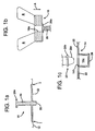
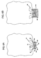
- an opening 18a is provided in the fluid-agitating element 18 and the first receiver 16 is a post 20 projecting toward the interior of the bag 10 (see Figures 1a and 1b ).
- the post 20 is sized for receiving the fluid-agitating element 18 by extending through the opening 18a formed in the body 18b thereof (which is depicted as being annular, but not necessarily circular in cross-section). As illustrated in Figure 1 , it is preferable that the size of the opening 18a is such that the fluid-agitating element 18 may freely rotate and move in the axial direction along the post 20 without contacting the outer surface thereof. Despite this freedom of movement, the post 20 serving as the first receiver 16 is still considered to hold, confine, or keep the fluid-agitating element 18 at a home location or expected position within the vessel 20 by contacting the surface adj acent to the opening 18a as a result of any side-to-side movement (the boundaries of which are defined by the dimensions of the opening).
- the flexible portion 12 of the bag 10 may be made ofthin (e.g., having a thickness of between 0.1 and 0.2 millimeters) polyethylene film.
- the film is preferably clear or translucent, although the use of opaque or colored films is also possible.
- the rigid portion 14 including the post 20 may be formed of plastic materials, such as high density polyethylene (HDPE), ultrahigh molecular weight (UHMW) polyethylene, or like materials. Of course, these materials do have some inherent flexibility when used to form relatively thin components or when a moderate amount of bending force is applied thereto. Despite this flexibility, the rigid portion 14 is distinguished from the flexible portion 12, in that it generally maintains its shape under the weight of any fluid introduced in the bag 10.
- HDPE high density polyethylene
- UHMW ultrahigh molecular weight
- the post 20 may include a portion 20a for capturing the fluid-agitating element 18 and assisting in holding it thereon.
- the portion 20a is preferably oversized and forms the head or end of the post 20.
- oversized it is meant that at least one dimension (length, width, diameter) of this portion 20a of the post 20 is greater than the corresponding dimension of the opening 18a in the fluid-agitating element 18.
- the portion 20a is shown in Figure 1 as being disc-shaped, such that it provides the head end of the post 20 with a generally T-shaped cross section.
- the oversized portion 20a is strategically positioned at a certain distance along the post 20.
- the post 20 may be removably attached to the rigid portion 14 through the opening 18a in the fluid-agitating element 18 (such as by providing a threaded bore in the rigid portion for receiving a threaded end of the post, or as shown in Figure 1c , a bore 14a having a groove 14b for establishing a snap-fit engagement with a corresponding projection 20b on a tapered end portion 20c of the post).
- this portion should be sufficiently thin such that it flexes or temporarily deforms to allow the fluid-agitating element 18 to pass initially (see Figure 1b and note action arrow A, which demonstrates the direction of force for deforming the oversized head 20a such that it passes through the opening 18a).
- this portion 20a of the post 20 need not be oversized, as defined above, but instead may simply be sufficiently close in size to that of the opening 18a such that the fluid-agitating element 18 must be precisely aligned and register with the post 20 in order to be received or removed. In any case, it is again important to note that the fluid-agitating element 18 is held in place in the vicinity of the post 20, but remains free of direct attachment.
- first receiver 16 confines or holds the fluid-agitating element 18 at a home location or expected position within the bag 10, it is still free to move side-to-side to some degree (which in this case is defined by the size of the opening 18a), and to move along the first receiver 16 in the axial direction (vertical, in the embodiment shown in Figure 1 ), as is necessary for levitation.
- the rigid portion 14 in this embodiment further includes a substantially planar peripheral flange 22.
- the flange 22 may be any shape or size, and is preferably attached or connected directly to the bag 10 at the interface I between the two structures (which may be created by overlapping the material forming the flexible portion 12 of the bag on an inside or outside surface of the flange 22 to form an overlapping joint, or possibly in some cases by forming a butt joint).
- the connection may be made using well-known techniques, such as ultrasonic or thermal welding (heat or laser) at the interface to form a hermetic seal.
- the bag 10 shown in Figure 1 maybe manufactured as described above, with the fluid-agitating element 18 received on the post 20 (which may be accomplished using the techniques shown in Figures 1b and 1c ).
- the empty bag 10 may than be sealed and folded for shipping, with the fluid-agitating element 18 held at the home location by the post 20. Holding in the axial direction (i.e., the vertical direction in Figure 1 ) may be accomplished by folding the bag 10 over the post 20, or by providing the portion 20a that is oversized or very close in size to the opening 18a in the fluid-agitaing element 18.
- the bag 10 When ready for use, the bag 10 is then unfolded. It may than be placed in a rigid or semi-rigid support structure, such as a container C, partially open along at least one end such that at least the rigid portion 14 remains exposed (see
- Fluid F may then be introduced into the bag 10, such as through an opening or fitting (which may be a sterile or aseptic fitting, in the case where the bag 10 is pre-sterilized or otherwise used in a sterile environment).
- an opening or fitting which may be a sterile or aseptic fitting, in the case where the bag 10 is pre-sterilized or otherwise used in a sterile environment.
- a fluid F liquid or gas under pressure
- An external motive device 24 is then used to cause the fluid-agitating element 18 (which is at least partially magnetic or ferromagnetic) to at least rotate to agitate any fluid F in the bag 10.
- the fluid-agitating element 18 is at least partially magnetic and is shown as being levitated by the motive device 24, which is optional but desirable.
- the levitation may be provided by a field-cooled, thermally isolated superconducting element SE (shown in phantom in Figure 2 ) positioned within the motive device 24 and thermally linked to a cooling source (not shown).
- the fluid-agitating element 18 may then be rotated by rotating the superconducting element SE (in which case the fluid-agitating element 18 should produce an asymmetric magnetic field, such as by using at least two spaced magnets having alternating polarities).
- a separate drive structure e.g., an electromagnetic coil
- a coupling capable of transmitting torque to the particular fluid-agitating element (which may be "levitated” by a hydrodynamic bearing; see, e.g., U.S. Patent No. 5,141,327 to Shiobara ).
- the fluid-agitating element 18 is also depicted as including a plurality of vanes or blades B to improve the degree of fluid agitation. If present, the vanes or blades B preferably project in a direction opposite the corresponding surface of the rigid portion 14.
- the particular number, type, and form of the vanes or blades B is not considered important, as long as the desired degree of fluid agitation for the particular application is provided. Indeed, in applications where only gentle agitation is required, such as to prevent damage to delicate suspensions or to merely prevent stagnation of the fluid F in the bag 10, the vanes or blades B need not be provided, as a rotating smooth-walled annular element 18 still provides some degree of agitation.
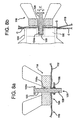
- the rigid portion 14 may be provided with a second receiver 26 to facilitate the correct positioning of the motive device 24 relative to the fluid-agitating element 18 when held at the home location.
- the second receiver 26 takes the form of a second post 28 projecting in a direction opposite the first post 20.
- the second post 28 is essentially coaxial with the first post 20 (although the post 20 may be a separate component that fits into a receiver 14a defined by the second post 28; see Figure 1c ) and is adapted to receive an opening 24a, such as a bore, in the adjacent end face 24b forming a part of the housing for the motive device 24. Consequently, the second post 28 helps to assure that the alignment between the fluid-agitating element 18 (which is generally held in the vicinity of the first receiver 16/post 20, which is the home location) and the motive device 14 is proper such that the desired coupling for transmitting the levitation or rotational force may be formed.
- the second receiver 26, such as second post 28 has a cross-sectional shape corresponding to the shape of the opening 24a.
- the second post 28 may be square in cross-section for fitting in a correspondingly-shaped opening 24a or locator bore.
- the second post 28 could have a triangular cross-sectional shape, in which case the opening 28 would be triangular.
- Myriad other shapes could also be used, as long as the shape of the second receiver 26 compliments that of the opening 24a such that it may be freely received therein.
- a system of matching receivers and openings may be used to ensure that the fluid-agitating element 18 in the bag 10 corresponds to particular motive device 24.
- the second receiver 26 may be provided with a certain shape that corresponds only to the opening 24 in the motive device 24 having that type of superconducting element or drive structure.
- a similar result could also be achieved using the relative sizes of the second receiver 26 and the opening 24a, as well as by making the size of the opening 18a in the fluid-agitating element 18 such that it only fits on a first receive 16 having a smaller width or diameter, and then making the second received 26 correspond only to an opening 24a in a motive device 24 corresponding to that fluid-agitating element 18.
- This structure serves to automatically align the motive device with the fluid-agitating element supported therein.
- a bag 10 per se is generally incapable of providing reliable support for the motive device 24, which can weigh as much as twenty kilograms.
- the motive device 24 in the embodiments disclosed herein for used with a vessel in the from of a bag 10 is generally supported from a stable support structure (not shwon), such as the floor, a wheeled, height adjustable platform, or the like. Since there is thus no direct attachment with the bag 10, the function performed by the second receiver 26 in aligning this device with the fluid-agitating element 18 is an important one.
- the vessel is agin a bag 10 including a flexible portion 12 and a rigid portion 14.
- the rigid portion 14 is cap or hat-shaped with a peripheral flange 22 for attachment to the flexible portion 12 of the bag 10.
- the connection between the two structures may be formed using the various techniques described above, and results in a fluid-impervious, hermetic seal.
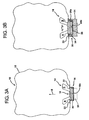
- the rigid portion 14 includes a first receiver 16 in the from of a recess or cavity 30 facing the interior of the bag (see action arrow B) for receiving a correspondingly-shaped portion of the fluid-agitating element 18 in the bag 10 and holding it at a home location, at least when oriented as shown in Figure 3a .
- the portion of the fluid-agitating element 18 received in the cavity 30 is preferably the body 18b, which as described above is at least partially magnetic or ferromagnetic and may optionally support a plurality of vanes or blades B.
- the body 18b of the fluid-agitating element 18 is circular in cross-section and the cavity 30 is sized and shaped such that the body (which need not include opening 18a in view of the absence of post 20) may freely be inserted, rotate, and levitate therein.
- the fluid-agitating element 18 could also be in the form of a conventional magnetic stirrer (which of course would not be levitated), such as a bar having a major dimension less than the corresponding dimension (e.g., the diameter) of the cavity 30.
- the fluid-agitating element 18 in this embodiment is again free of direct attachment from the first receiver 16, but is held at a home location, even in the event of accidental decoupling.
- the fluid-agitating element 18 may be positioned in the first receiver 16 in the bag 10.
- the bag 10 may then be sealed, folded for storage or shipping, stored or shipped, and ultimately umfolded for use.
- the folding is preferably compound such that the fluid-agitating element 18 is captured in the cavity 30 and remains held in place during shipping by an adjacent portion of the bag 10. Consequently, upon unfolding the bag 10, the fluid-agitating element 18 is at the expected or home location, but remains free of direct attachement and ready to be rotated (and possibly levitated).
- the levitation height established by the superconducting bearing or hydrodynamic bearing is preferably such that at least a portion of the body 18b of the fluid-agitating element 18 remains within the confines of the cavity 30. This helps to assure that the fluid-agitating element 18 remains held at the home location (that is, in the vicinity of the first receiver 16), even in the case of accidental decoupling from the motive device 24. In other words, in the event of an accidental decoupling, the fluid-agitating element 18 will engage the sidewall of the cavity 30 and simply come to rest therein, which defines the home location. This not only improves the chance of an automatic recoupling, but also makes the task of manually reforming the coupling an easy one.
- the non-contact coupling thus established helps ensure that the fluid-agitating element 18 remains in the home location prior to being coupled to an external motive device.
- the magnet 32 is removed once the bag 10 is positioned on or in a support structure, such as a container C (see Figure 2 ).
- a magnet 32 may also be used with the embodiment of Figure 1 , which eliminates the need for providing the post 20 with portion 20a.
- the magnet 32 is preferably annular with an opening that is received by the second receiver 26, which advantageously helps to ensure that the alignment is proper for forming the coupling.
- any adhesive used is preferably such that the bond is easily broken when the fluid-agitating element 18 is levitated in the first receiver 16.
- the use of such an adhesive might not be possible in situations where strict regulations govern the purity of the fluid being mixed.
- the first receiver 16 in this embodiment also serves the dual function of helping to align the fluid-agitating element 18 relative to an external motive device 24.
- the periphery of the sidewall 34 and the end wall 36 defining the cavity 30 in the rigid portion 14 define a second receiver 26 adapted to receive an opening 24a formed in an adjacent face of a motive device 24.
- the opening 24a is preferably sized and shaped for being received by the second receiver 26, and may even help to ensure that the bag 10 is used only with a motive device 24 having the correct superconducting element or magnetic structure(s) for levitating and/or rotating the fluid-agitating element 18.
- the opening 24a is also cylindrical.
- the opening 24a also has a depth such that the end wall 36 rests on the corresponding face 24c of the motive device 24.
- This feature may be important to ensure that the gap between the superconducting element and/or drive structure in the motive device 24 and the at least partially magnetic or ferromagnetic body 18b of the fluid-agitating element 18 is minimized, which helps to ensure that the strongest possible coupling is established and that the maximum amount of driving torque is transferred.
- the gaps are shown as being oversized in Figure 3b merely to provide a clear depiction of the relative interaction of the structures shown.
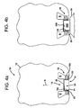
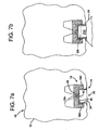
- Figures 4a and 4b show an embodiment similar in some respects to the one shown in Figure 3a and 3b .
- the rigid portion 14 includes a peripheral flange 22 connected to the flexible portion 12 of the bag 10 to form a seal.
- the rigid portion 14 includes a sidewall 34 and end wall 26 that together define a cavity 30.
- the cavity 30 of the rigid portion 14 essentially faces outwardly, or toward the exterior of the bag 10 (e.g., in a direction opposite action arrow B). Consequently, the sidewall 34 and end wall 36 define the first receiver 16 for receiving the fluid-agitating element 18, which is shown having an annular body 18b that is at least partially magnetic or ferromagnetic and may support a plurality of vanes or blades B.
- the first receiver 16 in the form of the periphery of the sidewall 34 provides a similar receiving function as both the post 20 and the cavity 30 of the other embodiments, since it is capable of maintaining, holding, or confining the fluid-agitating element 18 substantially in a home or expected position within the bag 10.
- the maximum amount of side-to-side movement is of course dependent on the size of the opening 18a in the fluid-agitating element.
- the outwardly-facing cavity 30 is adapted to serve as the second receiver 26 for receiving a portion of a motive device 24 used to levitate and rotate the fluid-agitating element 18 and serving to align the two.
- the motive device 24 may include a head end 24d adapted for insertion in the cavity 30 to form the desired coupling with the fluid-agitating element 18 positioned adjacent thereto.
- the spacing between the head end 24d and at least the sidewall 34 is preferably minimized to maximize the strength of the coupling between the motive device 24 and the fluid-agitating element 18.
- the end face 24b of the head end 24d may rest against and assist in supporting the bag 10 (which, as described above, may be positioned in a separate, semi-rigid container (not shown)).
- an added advantage of the use of the first receiver 16 in each of the above-referenced embodiments is that, despite being free from direct attachment, it still serves the function of holding the fluid-agitating element 18 at the home location in instances where accidental decoupling occurs. This significantly reduces the downtime associated with such an event, since the general position of the fluid-agitating element 18 is known.
- the use of a first receiver in the bag 10 also improves the chances of automatic recoupling, since the fluid-agitating element 18 remains generally centered relative to the motive device 14 and held generally at the home location, even when decoupling occurs.
- a related advantage is provided by forming the first receiver 16 in or on a rigid portion 14 of the bag 10.
- the contact over time could result in damage and could even lead to an accidental perforation, which is deleterious for obvious reasons.
- the possibility for such damage or perforation also exists when a levitating fluid-agitating element 18 accidentally decouples.
- the potential for such damage or perforation is substantially eliminated in the foregoing embodiments, since the first receiver 16 helps to keep the fluid-agitating element 18 adjacent to the flange 22 of the rigid portion 14, which is generally thicker and less susceptible to being damaged or perforated.
- the flange 22 it only engages or contacts the rigid portion 14 of the bag 10.
- the flange 22 it is preferable for the flange 22 to be oversized relative to the fluid-agitating element 18
- the present invention extends to a completely rigid vessel (that is, one made of metal, glass, rigid plastics, or the like).
- the post 20 preferably includes a portion 20a for capturing the fluid-agitating element 18 thereon, but without any other means of direct attachment or bearing.
- the inventions described herein may also be applied to a bag 10 in combination with a fluid-agitating element 18 directly supported by one or more bearings.
- the first receiver 16 associated with the rigid portion 14 of the bag 10 may be in the form of an inwardly-projecting post 20 including a slide bearing 40 for providing direct support for the fluid-agitating element 18.
- the bearing 40 is preferably sized and shaped such that it fits into an opening 18a forming in the fluid-agitating element 18, which may rest on the adjacent surface of the post 20 or may be elevated slightly above it.
- the first receiver 16 receives and holds the fluid-agitating element 18 in a home location, both during shipping and later use.
- the material forming the slide bearing 40 is preferably highly wear-resistant with good tribological characteristics.
- the use of a slide bearing 40 is preferred in applications where the bag 10 is disposable and is merely discarded, since it is less expensive than a corresponding type of mechanical roller bearing (and is actually preferred even in the case where the bag 10 is reused, since it is easier to clean).
- the rigid portion 14 of the bag 10 in this embodiment may further include a second receiver 26 in the form of a second post 28 coextensive and coaxial with the first post 20.
- the second post 28 is received in an opening 24a formed in an end face 24b of a motive device 24.
- the motive device 24 in this case includes only a drive structure DS (shown in phantom in Figure 5b ) for forming a coupling with the body 18b, which is magnetic or ferromagnetic (iron, magnetic steel, etc.).
- the drive structure DS may be a permanent magnet or may be ferromagnetic, as necessary for forming the coupling with the fluid-agitating element 18, which may be disc-shaped, cross-shaped, an elongated bar, or have any other suitable shape.
- the drive structure DS may be rotated by a direct connection with a motor (not shown), such as a variable speed electric motor, to induce rotation in the fluid-agitating element 18.
- the drive structure DS may be an electromagnet with windings to which current is supplied to cause the magnetic fluid-agitating element 18 rotate and possibly levitate slightly to create a hydrodynamic bearing (see, e.g., U.S. Patent No. 5,141,327 , the disclosure of which is incorporated herein by reference).
- the particular type of motive device 24 employed is not considered critical to the present invention.
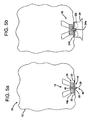
- Figures 6a and 6b show an embodiment of the bag 10 in which the first receiver 16 is in the form of a cavity 30 formed in the rigid portion 14 and facing inwardly.
- a bearing 40 is provided in the cavity 30 for providing direct support for a fluid-agitating element 18 positioned therein.
- the bearing 40 may be a slide bearing adapted for insertion in the opening 18a of the fluid-agitating element 18 formed on the head end of a post 42.
- the post 42 may be supported by or unitarily formed with the end wall 36.
- the periphery of the sidewall 34 also defines a second receiver 26 for receiving a corresponding opening 24a in a motive device 24, which in view of the direct support provided by bearing 40 need only provide the force necessary to rotate the fluid-agitating element 1 S in a non-contact fashion.
- the rigid portion 14 again includes a cavity 30 facing outwardly or toward the exterior of the bag 10 and a first receiver 16 for receiving and defining a home location for a fluid-agitating element 18.
- the first receiver 16 includes a bearing 40 for supporting the fluid-agitating element 18, which again is at least partially magnetic or ferromagnetic.
- the bearing 40 may be a slide bearing formed on the head end of a post 44 integral with the end wall 36 of the rigid portion 14 and adapted for fitting into an opening or recess 18a in the fluid-agitating element 18, or may be a different type of bearing for providing support therefor.
- the motive device 24 includes a head end 24d adapted for insertion in a second receiver 26 defined by the cavity 30.
- This head end 24d preferably includes the drive structure DS that provides the force for causing the at least partially magnetic or ferromagnetic fluid-agitating element 18 to rotate about bearing 40.
- the fluid-agitating element 18 includes an optional depending portion18b that extends over the sidewall 34. As should be appreciated, this portion may also be magnetized or ferromagnetic such that a coupling is formed with the drive structure DS.
- a similar type of fluid-agitating element 18 could also be used in the levitation scheme of Figures 4a and 4b .
- FIGS 8a and 8b show another possible embodiment of a vessel of the present invention for use in a fluid-agitating or mixing system.
- the vessel for holding the fluid is shown as being a bag 110 having a flexible portion 112, generally cylindrical in shape, and substantially or hermetically sealed from the ambient environment.
- the bag 110 includes a first receiver 116 for receiving and holding the fluid-agitating element 118 at a home location.
- the first receiver 116 is in the form of a post 120 adapted to receive the fluid-agitating element 118, which has a corresponding opening 118a.
- the post 120 preferably includes an oversized head portion 120athat captures the fluid-agitating element 118, both before and after a fluid is introduced into the bag 110.
- the bag 110 may be manufactured, sealed (if desired), shipped, or stored prior to use with the fluid-agitating element 118 held in place on the post 120.
- the vessel 110 may also be sterilized as necessary for a particular application, and in the case of a flexible bag, may even be folded for compact storage.
- the post 120 also serves the advantageous function of keeping, holding, maintaining, or confining the fluid-agitating element 118 substantially at a home location or "centered,” should it accidentally become decoupled from the adjacent motive device, which as described above may include a rotating superconducting element SE for not only providing the rotational force, but also a levitation force.
- the post 120 is shown as being defined by an elongated, rigid or semi-rigid, rod-like structure inserted through an opening typically found in the flexible plastic bags frequently used in the bioprocessing industry (pharmaceuticals, food products, cell cultures, etc.), such as a rigid or semi-rigid fitting or nipple 134.
- the oversized portion 120a which is shown as being T-shaped in cross-section, is preferably sufficiently thin and/or formed of a material that may flex or deform to easily pass through the opening in the nipple 134, as well as through the opening 118a in the fluid-agitating element 118.
- a conventional clamp 136 such as a cable tie, may be used to form a fluid-impervious seal between the nipple 134 and the post 120. Any other nipples or fittings present may be used for introducing the fluid F prior to mixing, retrieving a fluid during mixing or after mixing is complete, or circulating the fluid.
- the use of the rod/nipple combination allows for easy retrofitting.
- the oversized head portion 120a may be cross-shaped, L-shaped, Y-shaped, spherical, cubic, or may have any other shape, as long as the corresponding function of capturing the fluid-agitating element 118 is provided.
- the head portion 120a may be integrally formed, or may be provided as a separate component clamped or fastened to the post 120.
- the bag 110 may also include a second receiver 126 that helps to ensure that proper alignment is achieved between the fluid-agitating element 118 and an adjacent structure, such as a support structure or a device for rotating and/or levitating the element.
- this second receiver 126 is shown as the opposite end 128 of the rod forming post 120.
- This end 128 of the rod may be inserted in a bore or opening 124a in an adjacent surface of a motive device 124 to assure proper alignment with the fluid-agitating element 118.
- assurance is thus provided that the fluid-agitating element 118 is in the desired home or expected position for forming a coupling with an adjacent motive device 124.
- Figure 8a also shows the post 120 forming the first receiver 116 as projecting upwardly from a bottom wall of the vessel 110, but as should be appreciated, it could extend from any wall or other portion thereof.
- the rod serving as both the first and second receivers 116,126 may be positioned substantially perpendicular to a vertical plane.
- the bag 110 is positioned in a rigid or semi-rigid support container C having an opening O.
- the end 128 of the rod is positioned in the opening O such that it projects therefrom and may be inserted in the opening 124a formed in the motive device 124, which includes a superconducting element SE and may still levitate, and possibly rotate the at least partially magnetic fluid-agitating element 118 in this position.
- the portion of the rod extending outside the bag 110 and forming the second receiver 126 is greater in length than that in the embodiment shown in Figure 1 , and the depth of the opening 124a in the motive device 124 corresponds to this length.
- This in combination with the rigid or semi-rigid nature of the nipple 134 helps to ensure that the other end of the rod forming post 120 is properly aligned with the fluid-agitating element 118 when the magnetic coupling is formed.
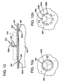
- a first receiver 216 in the form of a post 220 includes an oversized spherical head 220a that serves to mechanically capture an adjacent fluid-agitating element 218 (shown in phantom).
- the post 220 is integrally formed with the vessel, which is preferably a bag 210 but may be partially or completely rigid.
- a low-profile second receiver 226 in the form of an outwardly-directed projection 228 is provided for receiving a corresponding portion 224a of the adjacent motive device 224.
- the projection 228 may have any shape desired, including square, circular, or the like (see Figures 9a and 9b ), with the portion 224a having a corresponding shape. Once the projection 228 is aligns with and receives the corresponding portion 224a, the captive fluid-agitating element 218 is properly aligned with the adjacent motive device 224.
- the vessel 310 may be rigid or at least partially flexible.
- the first receiver 316 is a post 320, which is shown merely for purposes of illustration as having an L-shaped head portion 320a for mechanically capturing an adjacent fluid-agitating element 318 (shown in phantom).
- the second receiver 326 is in the form of at least one projection 328 substantially concentric with the post 320.
- the projection 328 may be square, circular, or may have any other desired shape.
- the projection may also be continuous, as shown in Figure 10a , or interrupted to form segments 328a, 328b... 328n, as shown in Figure 10b .
- the corresponding portion 324a of the motive device 324 that is received by the second receiver 326 is similarly shaped and preferably continuous, but could also have one or more segments matching the segments in the vessel 310 (including a single offset bore).
- the vessel 410 includes a first receiver 416 in the form of a post 420, again shown with an oversized T-shaped head 420a.
- the second receiver 426 includes at least one channel, recess, or groove 428 formed in the vessel 410.
- a corresponding projection 425 is provided in the motive device 424 for engaging the channel, recess or groove 428 to provide the desired alignment function, such as between driving magnets and driven magnets, between driven magnets and a rotating superconducting element, or between any other driver and a driven structure associated with a fluid-agitating element.
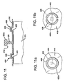
- the channel, groove, or recess 428 is preferably continuous (see Figure 11a , with the projection 425 shown in phantom), but may be segmented as well (see Figure 11b ).
- the vessel 510 again includes a first receiver 516 in the form of a post 520, which is shown for purposes of illustration as having a frusto-conical head to create a Y-shaped cross-section.
- the second receiver 526 is in the form of a low-profile recessed portion 528 formed in the vessel 510.
- This recessed portion 528 is sized and shaped for receiving a portion of the motive device 510, and thus ensures that the proper alignment is achieved between a fluid-agitating element 518 concentric with the post 520 and any structure for levitating and/or rotating the element.
- the recessed portion 528 may have any shape desired, including square, circular, triangular, rectangular, polygonal, or the like.
- FIG. 14 shows an embodiment wherein the vessel 710, which again may be rigid or partially flexible, includes a first receiver 716 in the form of a post 720 having an oversized head portion 720a and a second receiver 726 in the form of a hat or cup-shaped projection 728 (which may be integrally formed or a separate rigid portion).
- the second receiver 726 receives a portion of an intermediate support structure T including a first recess R 1 on one side and a second recess R 2 on the opposite side.
- the second recess R 2 is adapted for receiving at least a portion of the motive device 724, which is shown as a cryostat including a rotating, thermally isolated superconducting element SE for coupling with at least two alternating polarity magnets M (or alternatively, the head of the cryostat may be attached to a bearing positioned in recess R 2 and rotated).
- This particular embodiment dispenses with the need for forming a locator bore in the motive device 724 to align the fluid-agitating element 718 therewith (although it remains possible to provide such a bore for receiving a projection on the support structure T to achieve the alignment function).
- Figure 15 shows an embodiment where a second receiver 826 in the form of a slightly raised projection 828 is provided in the vessel 810 that corresponds to a dimple 825 formed in an external structure, such as the end face of the motive device 824.
- the opposite arrangement could also be used, with the dimple formed in the vessel 810 and serving as a second receiver 826.
- at least one indicia may be provided to allow an observer to determine the proper location of the structure such as motive device 824 relative to the vessel 810.
- the indicia is shown as a darkened ring 866 formed in the outer wall of the vessel 810, which could be a bag or a rigid or semi-rigid container.
- the indicia could be in the form of one or more marks placed on or formed in the outer surface of the vessel 810 (including even possibly a weld or seal line), or even marks placed on the opposite sides of an intermediate support surface (not shown).
- the indicia 866 is preferably designed such that it helps to align the motive device 824 relative to a first receiver 816 in the vessel 810 for receiving and defining a home location for a fluid agitating element, such as the post 820 (which is shown having a cross-shaped head 820a). The indicia 866 thus helps to ensure that the fluid-agitating element is aligned with any driving or levitating structure held therein.
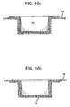
- the rigid portion 14 as part of the bag 10 by forming a seal at an interface between the two, it could also be positioned in contact to an inner or outer surface of the bag and attached using vacuum-forming techniques, adhesives, or the like.
- the bag 10 would essentially line the inside surfaces of the sidewall 34 and end wall 36 (see Figure 16a ).
- the bag 10 would cover the sidewall 34 and end wall 36 (see Figure 16b ). In both cases, the need for the flange 22 may be eliminated.
- any of the first receivers with a tapered or frusto-conical engagement surface that mates with a corresponding surface on the fluid-agitating element, as disclosed in my co-pending patent application Ser. No. PCT/US01/31459 , published as WO 02/41484 A2 ,
Claims (15)
- - Récipient (10) destiné à recevoir un fluide comprenant un sac (10) pour recevoir et contenir le fluide, un élément d'agitation de fluide (18) disposé dans le sac (10), le sac (10) comprenant une partie souple (12) et une partie rigide (14), caractérisé par le fait que la partie rigide (14) comprend un premier organe de réception (16) pour recevoir et maintenir l'élément d'agitation de fluide (18) à une localisation nominale ou à une position attendue à l'intérieur du sac (10) pour une rotation relative par rapport au premier organe de réception (16) et par le fait que le premier organe de réception (16) comprend un rebord périphérique (22) formant un scellement hermétique avec la partie souple du sac.
- - Récipient selon la revendication 1, dans lequel le premier organe de réception (16) comprend un premier montant se projetant vers l'intérieur (20) pour un positionnement dans une ouverture ou une cavité dans l'élément d'agitation de fluide (18).
- - Récipient selon la revendication 2, dans lequel le premier montant (20) comprend une partie surdimensionnée (20a) pour capturer l'élément d'agitation de fluide (18).
- - Récipient selon la revendication 3, dans lequel la partie surdimensionnée (20a) est la tête du montant (20) et est formée sous une forme qui confine l'élément d'agitation de fluide (18) adjacent au montant (20), qui peut, par exemple, être une forme de T, de croix, de Y, de L, sphérique ou cubique.
- - Récipient selon la revendication 1, comprenant en outre un second organe de réception (26) se projetant vers l'extérieur à partir du sac (10), le second
organe de réception (26) facilitant l'alignement de l'élément d'agitation de fluide (18) avec une structure externe, telle qu'un dispositif moteur (24) pour faire léviter ou faire tourner l'élément d'agitation de fluide (18). - - Récipient selon la revendication 5, dans lequel le premier organe de réception (16) est un premier montant se projetant vers l'intérieur (20) et le second organe de réception (26) est un second montant se projetant vers l'extérieur (28) coaxial au premier montant se projetant vers l'intérieur (20).
- - Récipient selon la revendication 1, dans lequel le premier organe de réception (16) se présente sous la forme d'un capuchon et comprend une cavité (14a) dirigée vers l'intérieur du sac.
- - Récipient selon la revendication 1, dans lequel le premier organe de réception (16) comprend une paroi latérale périphérique généralement verticale (34) sur laquelle l'élément d'agitation de fluide est reçu et une cavité (30) apte à recevoir une partie d'une structure externe pour faire tourner l'élément d'agitation de fluide (18).
- - Récipient selon la revendication 1, dans lequel le premier organe de réception (16) comprend un support pour engager et supporter directement l'élément d'agitation de fluide (18) d'une manière sans lévitation.
- - Récipient selon la revendication 1, dans lequel le premier organe de réception (16) est défini par une partie rigide en forme de capuchon, ayant une cavité (14a) et un rebord périphérique (22) relié à la partie souple (12), la cavité (14a) étant dirigée vers l'intérieur du sac (10) pour recevoir l'élément d'agitation de fluide (18) lorsqu'il est positionné dans celui-ci.
- - Récipient selon la revendication 10, dans lequel le premier montant dirigé vers l'intérieur (20) est positionné au moins partiellement dans la cavité (14a) de l'organe de réception (16).
- - Récipient selon la revendication 9, dans lequel le premier montant dirigé vers l'intérieur (20) comprend un support pour supporter directement l'élément d'agitation de fluide (18).
- - Récipient selon la revendication 1, dans lequel l'élément d'agitation de fluide (18) est au moins partiellement magnétique et comprend au moins une pale ou une aube (B).
- - Récipient selon la revendication 1, dans lequel l'élément d'agitation de fluide (18) comprend un agitateur magnétique.
- - Procédé de positionnement d'un élément d'agitation de fluide (18) dans un sac (10) destiné à recevoir un fluide ayant besoin d'être agité, comprenant le fait de doter le sac (10) d'une partie rigide (14) comprenant un premier organe de réception (16) pour recevoir et maintenir l'élément d'agitation de fluide (18) à une localisation nominale pour une rotation relative par rapport au premier organe de réception (16) lorsqu'il est positionné dans le sac, le premier organe de réception (16) comprenant un rebord périphérique (22) formant un scellement hermétique avec une partie souple du sac (10).
Priority Applications (1)
| Application Number | Priority Date | Filing Date | Title |
|---|---|---|---|
| EP10165402.8A EP2228128B1 (fr) | 2001-10-03 | 2002-10-02 | Récipient de mélange possédant un dispositif de retenue pour un élément agitateur de fluide |
Applications Claiming Priority (3)
| Application Number | Priority Date | Filing Date | Title |
|---|---|---|---|
| US32683301P | 2001-10-03 | 2001-10-03 | |
| US326833P | 2001-10-03 | ||
| PCT/US2002/031478 WO2003028869A2 (fr) | 2001-10-03 | 2002-10-02 | Recipient ou sac de melange possedant un receptacle pour un element agitateur de fluide |
Related Child Applications (1)
| Application Number | Title | Priority Date | Filing Date |
|---|---|---|---|
| EP10165402.8 Division-Into | 2010-06-09 |
Publications (3)
| Publication Number | Publication Date |
|---|---|
| EP1534412A2 EP1534412A2 (fr) | 2005-06-01 |
| EP1534412A4 EP1534412A4 (fr) | 2006-05-10 |
| EP1534412B1 true EP1534412B1 (fr) | 2010-08-18 |
Family
ID=23273905
Family Applications (2)
| Application Number | Title | Priority Date | Filing Date |
|---|---|---|---|
| EP02800450A Expired - Lifetime EP1534412B1 (fr) | 2001-10-03 | 2002-10-02 | Recipient de melange possedant un receptacle pour un element agitateur de fluide |
| EP10165402.8A Expired - Lifetime EP2228128B1 (fr) | 2001-10-03 | 2002-10-02 | Récipient de mélange possédant un dispositif de retenue pour un élément agitateur de fluide |
Family Applications After (1)
| Application Number | Title | Priority Date | Filing Date |
|---|---|---|---|
| EP10165402.8A Expired - Lifetime EP2228128B1 (fr) | 2001-10-03 | 2002-10-02 | Récipient de mélange possédant un dispositif de retenue pour un élément agitateur de fluide |
Country Status (9)
| Country | Link |
|---|---|
| US (2) | US7481572B2 (fr) |
| EP (2) | EP1534412B1 (fr) |
| JP (1) | JP4645033B2 (fr) |
| AT (1) | ATE477843T1 (fr) |
| AU (1) | AU2002362448A1 (fr) |
| CA (1) | CA2462309C (fr) |
| DE (1) | DE60237405D1 (fr) |
| IL (2) | IL161280A0 (fr) |
| WO (1) | WO2003028869A2 (fr) |
Families Citing this family (99)
| Publication number | Priority date | Publication date | Assignee | Title |
|---|---|---|---|---|
| US6758593B1 (en) * | 2000-10-09 | 2004-07-06 | Levtech, Inc. | Pumping or mixing system using a levitating magnetic element, related system components, and related methods |
| CA2425584C (fr) * | 2000-10-09 | 2012-03-20 | Levtech, Inc. | Recipient pour un systeme de pompage ou de melangeage |
| US7086778B2 (en) * | 2000-10-09 | 2006-08-08 | Levtech, Inc. | System using a levitating, rotating pumping or mixing element and related methods |
| US8182137B2 (en) * | 2000-10-09 | 2012-05-22 | Atmi Packaging, Inc. | Mixing bag or vessel with a fluid-agitating element |
| US7762716B2 (en) * | 2000-10-09 | 2010-07-27 | Levtech, Inc. | Mixing vessel with a fluid-agitating element supported by a roller bearing |
| EP1534412B1 (fr) * | 2001-10-03 | 2010-08-18 | Levtech Inc. | Recipient de melange possedant un receptacle pour un element agitateur de fluide |
| GB2414808A (en) * | 2002-02-08 | 2005-12-07 | Uni Chemical Co Ltd | A magnetic stirring device for viscosity measurement |
| JP3884694B2 (ja) * | 2002-02-08 | 2007-02-21 | ユニケミカル株式会社 | 粘度変化検知用素子、それを用いた粘度変化検知用攪拌回転子、及びそれらを用いた攪拌装置 |
| US6923567B2 (en) | 2002-04-12 | 2005-08-02 | Hynetics Llc | Mixing tank assembly |
| US6908223B2 (en) | 2002-04-12 | 2005-06-21 | Hynetics Llc | Systems for mixing liquid solutions and methods of manufacture |
| US6981794B2 (en) | 2002-04-12 | 2006-01-03 | Hynetics Llc | Methods for mixing solutions |
| US7153021B2 (en) * | 2003-03-28 | 2006-12-26 | Hyclone Laboratories, Inc. | Container systems for mixing fluids with a magnetic stir bar |
| US7249880B2 (en) | 2003-10-14 | 2007-07-31 | Advanced Technology Materials, Inc. | Flexible mixing bag for mixing solids, liquids and gases |
| CA2552717C (fr) | 2004-01-07 | 2011-11-29 | Levtech, Inc. | Sac melangeur a arroseur integre et receptacle pour detecteur |
| DE102004013078B4 (de) * | 2004-03-17 | 2010-12-09 | Sartorius Stedim Biotech Gmbh | Mischeinrichtung für Flüssigkeiten in flexiblen Einwegbehältern |
| MXPA06011837A (es) | 2004-04-27 | 2007-01-16 | Baxter Int | Sistema de reactor de tanque agitado. |
| WO2005118771A2 (fr) * | 2004-06-04 | 2005-12-15 | Xcellerex, Inc. | Systemes de bioreacteurs jetables et procedes associes |
| JP2008504118A (ja) * | 2004-06-23 | 2008-02-14 | リーブテック,インコーポレイテッド | 混合用容器心合システム、デバイス及びそれらに関連する方法 |
| US7682067B2 (en) * | 2005-04-22 | 2010-03-23 | Hyclone Laboratories, Inc. | Mixing systems and related mixers |
| EP1748201B1 (fr) * | 2005-07-29 | 2010-12-29 | Zeta Biopharma GmbH | Mélangeur magnétique |
| RU2388530C2 (ru) * | 2005-08-31 | 2010-05-10 | Синвент Ас | Магнитная перемешивающая система в ячейке для исследования давления, объема и температуры |
| WO2008040567A1 (fr) * | 2006-10-03 | 2008-04-10 | Artelis | Sac mélangeur souple, dispositif mélangeur et système mélangeur associé |
| CN101300338B (zh) * | 2005-10-26 | 2015-10-21 | Atmi包装公司 | 具有混合器和喷射器的生物反应器 |
| DE102006001623B4 (de) * | 2006-01-11 | 2009-05-07 | Sartorius Stedim Biotech Gmbh | Behälter und Verfahren zum Mischen von Medien |
| US8104328B2 (en) * | 2006-03-22 | 2012-01-31 | Atmi Packaging, Inc. | Apparatus and methods for leak detection in bioprocessing bags |
| SE531572C2 (sv) * | 2006-04-05 | 2009-05-26 | Millipore Ab | Engångsenhet för processa produkter |
| US8366311B2 (en) * | 2006-04-21 | 2013-02-05 | Atmi Bvba | Systems and devices for mixing substances and methods of making same |
| DE102006020461B3 (de) * | 2006-04-28 | 2007-10-04 | Sartorius Biotech Gmbh | Behälter mit flexiblen Wänden |
| WO2007134267A2 (fr) | 2006-05-13 | 2007-11-22 | Advanced Technology Materials, Inc. | Bioréacteur jetable |
| US20080151686A1 (en) * | 2006-11-14 | 2008-06-26 | Charles Meadows | Mixing bag for use with nonabrasive stir bar |
| US20100157725A1 (en) * | 2007-02-21 | 2010-06-24 | Terentiev Alexandre N | Roller Bearing for a Fluid-Agitating Element and Associated Vessel |
| EP2155852B1 (fr) * | 2007-06-15 | 2013-10-09 | Cellution Biotech B.V. | Bioréacteur flexible amélioré |
| US8312871B1 (en) * | 2008-01-11 | 2012-11-20 | Donald Lee Kulp | Induction drive mechanism for a paintball loader |
| US8459862B2 (en) * | 2008-03-05 | 2013-06-11 | Panasonic Corporation | Stirring device, microbe testing device, and microbe testing method |
| WO2009122310A2 (fr) * | 2008-03-19 | 2009-10-08 | Sartorius Stedim Biotech Gmbh | Récipient mélangeur jetable |
| EP2103547B1 (fr) * | 2008-03-22 | 2013-03-20 | Pall Corporation | Bio récipient |
| DE102008025507A1 (de) * | 2008-05-28 | 2009-12-03 | Sartorius Stedim Biotech Gmbh | Mischsystem |
| US8459245B1 (en) * | 2009-01-09 | 2013-06-11 | Budster Enterprises, LLC | Induction drive mechanism for a paintball loader |
| US8282268B2 (en) * | 2009-02-24 | 2012-10-09 | Island Oasis Frozen Cocktail Co., Inc. | Magnetic drive for food processing apparatus |
| FR2943560B1 (fr) * | 2009-03-24 | 2011-05-27 | Jean Pascal Zambaux | Bioreacteur jetable et systeme d'agitation a usage unique |
| US20100282099A1 (en) * | 2009-05-08 | 2010-11-11 | Lahav Gil | Magnetic Homogenizer Apparatus |
| US20100302899A1 (en) * | 2009-05-26 | 2010-12-02 | Dermody Daniel L | Material handling apparatus, system, and method |
| DE102009052670B4 (de) * | 2009-11-12 | 2017-10-05 | Sartorius Stedim Biotech Gmbh | Begasungsvorrichtung für Bioreaktoren |
| EP2528680B1 (fr) | 2010-01-28 | 2018-08-22 | Pall Life Sciences Belgium | Cuve à évacuation latérale réglable |
| SE534819C2 (sv) * | 2010-05-06 | 2012-01-10 | Itt Mfg Enterprises Inc | Omröraraggregat för rötkammare |
| JP4792118B1 (ja) * | 2010-06-01 | 2011-10-12 | シャープ株式会社 | 炊飯器 |
| DE102010046989B4 (de) * | 2010-09-30 | 2015-07-30 | Sartorius Stedim Biotech Gmbh | Begasungsvorrichtung für Bioreaktoren |
| US8408418B2 (en) * | 2010-11-05 | 2013-04-02 | Michael D. Stolzman | Drum cover with center support |
| KR20120058293A (ko) * | 2010-11-29 | 2012-06-07 | 백원옥 | 마그네틱을 이용한 일회용 미생물 배양용기 및 배양장치 |
| WO2012077843A1 (fr) * | 2010-12-09 | 2012-06-14 | 한국과학기술원 | Générateur de plasma |
| FR2969506B1 (fr) | 2010-12-22 | 2013-02-15 | Sartorius Stedim Biotech Sa | Melange du contenu d'un conteneur flexible a usage biopharmaceutique. |
| US9314751B2 (en) | 2011-01-07 | 2016-04-19 | Life Technologies Corporation | Methods and apparatus for mixing and shipping fluids |
| US8608369B2 (en) | 2011-01-07 | 2013-12-17 | Hyclone Laboratories, Inc. | Methods and systems for heating and mixing fluids |
| ES2393378B1 (es) * | 2011-06-07 | 2013-10-31 | Electrodomésticos Taurus, S.L. | Encimera de cocina con medios de accionamiento giratorio y recipiente de cocina utilizable con dicha encimera |
| EP3922712A3 (fr) | 2011-10-25 | 2022-03-09 | Life Technologies Corporation | Systèmes de mélange de fluides munis d'élément de mélange réglable |
| JP6253032B2 (ja) * | 2012-05-18 | 2017-12-27 | ポール ライフ サイエンシズ ベルジウム ビーヴイビーエーPall Life Sciences Belgium Bvba | 流体取扱用コンテナ、システム、及び関連する方法 |
| US9339026B2 (en) | 2012-06-14 | 2016-05-17 | Therapeutic Proteins International, LLC | Pneumatically agitated and aerated single-use bioreactor |
| WO2014008336A1 (fr) | 2012-07-03 | 2014-01-09 | Atmi Bvba | Mélangeur entraîné par fluide et procédés associés |
| US9321558B2 (en) * | 2012-09-19 | 2016-04-26 | Perimeter Brand Packaging, Llc | Insert assembly for beverage container |
| DE102012020384B4 (de) | 2012-10-18 | 2014-07-10 | Sartorius Stedim Biotech Gmbh | Bioreaktor, Reaktorbeutel dafür und Rührer zur Umwälzung seines Inhaltes |
| JP6017060B2 (ja) | 2012-11-29 | 2016-10-26 | イー・エム・デイー・ミリポア・コーポレイシヨン | フード付き磁気インペラアセンブリを備える容器 |
| SG10201708995SA (en) | 2012-11-29 | 2017-11-29 | Emd Millipore Corp | 2d low level mixing bag for storage and shipping |
| US9827541B1 (en) | 2012-11-29 | 2017-11-28 | Emd Millipore Corporation | 2D low level mixing bag for storage and shipping |
| EP2777455B1 (fr) | 2013-03-15 | 2016-01-06 | Whirlpool Corporation | Appareil de mélange d'entraînement latéral à profil bas |
| US20140334249A1 (en) * | 2013-05-08 | 2014-11-13 | Roxi Group, Inc. | Beverage mixing, storing and dispensing apparatus |
| EP3004319B1 (fr) * | 2013-06-05 | 2018-12-19 | GE Healthcare Bio-Sciences AB | Récipient jetable et système de mélangeage comprenant le récipient |
| BR112015031637B1 (pt) * | 2013-06-28 | 2022-01-18 | Saint-Gobain Performance Plastics Corporation | Conjuntos de mistura incluindo impelidores magnéticos |
| US11944946B2 (en) * | 2013-06-28 | 2024-04-02 | Saint-Gobain Performance Plastics Corporation | Mixing assemblies including magnetic impellers |
| JP6125018B2 (ja) * | 2013-08-05 | 2017-05-10 | シャープ株式会社 | 撹拌羽根、撹拌装置および飲料製造装置 |
| CN110172406B (zh) | 2013-09-16 | 2023-08-08 | 豪夫迈·罗氏有限公司 | 具有多个或可调节位置的搅拌器设计的生物反应器 |
| US9555384B2 (en) | 2013-10-25 | 2017-01-31 | Whirlpool Corporation | Blender assembly |
| US9815037B2 (en) * | 2013-10-25 | 2017-11-14 | Whirlpook Corporation | Magnetic disc coupler |
| JP6248282B2 (ja) * | 2014-02-26 | 2017-12-20 | パナソニックIpマネジメント株式会社 | 撹拌体および撹拌機能付き容器および加熱撹拌調理器 |
| US9101893B1 (en) | 2014-03-17 | 2015-08-11 | Advanced Scientifics, Inc. | Mixing assembly and mixing method |
| US8979357B1 (en) | 2014-03-17 | 2015-03-17 | Advanced Scientifics, Inc. | Transportable mixing system for biological and pharmaceutical materials |
| US10357748B2 (en) | 2014-03-28 | 2019-07-23 | Asepco | Magnetically coupled mixer with thrust bearing friction control |
| US10092139B2 (en) | 2014-04-28 | 2018-10-09 | Whirlpool Corporation | Low profile motor for portable appliances |
| US9643142B2 (en) | 2014-07-01 | 2017-05-09 | Advanced Scientifics, Inc. | Plunge-mixing bag arrangement and plunge-mixing system |
| EP2990373B1 (fr) * | 2014-08-29 | 2018-10-03 | Sidel S.p.a. Con Socio Unico | Ensemble de réservoir d'agitation de liquide pour machine de remplissage de récipients |
| CA2871904A1 (fr) * | 2014-11-20 | 2016-05-20 | Raison Investments Inc. | Paille de melange et degustation actionnee magnetiquement |
| CN113144983A (zh) | 2015-04-16 | 2021-07-23 | 通用电气医疗集团生物科学公司 | 生物处理混合器 |
| JP6068709B2 (ja) * | 2015-05-18 | 2017-01-25 | シャープ株式会社 | 撹拌子および撹拌装置 |
| EP3115103B1 (fr) * | 2015-07-06 | 2021-04-21 | Levitronix GmbH | Dispositif de mélange et dispositif jetable pour un tel dispositif de mélange |
| JP6461735B2 (ja) * | 2015-07-10 | 2019-01-30 | 株式会社荏原製作所 | ファンスクラバー、及び、真空ポンプ装置 |
| DE102015009895B4 (de) | 2015-07-30 | 2019-08-14 | Sartorius Stedim Biotech Gmbh | Mischsystem, Mischvorrichtung, Behälter und Verfahren zum Mischen eines Fluids und/oder eines Feststoffs |
| US10177627B2 (en) * | 2015-08-06 | 2019-01-08 | Massachusetts Institute Of Technology | Homopolar, flux-biased hysteresis bearingless motor |
| ITUB20159336A1 (it) * | 2015-12-14 | 2017-06-14 | Sipp S R L Soc A Socio Unico | Procedimento e attrezzatura di spillatura |
| TWI551249B (zh) * | 2016-01-08 | 2016-10-01 | 永順利食品機械股份有限公司 | 煮鍋 |
| EP3405279A4 (fr) * | 2016-01-22 | 2019-11-27 | Saint-Gobain Performance Plastics Corporation | Système de mélange de fluides |
| US11097236B2 (en) | 2016-03-31 | 2021-08-24 | Global Life Sciences Solutions Usa Llc | Magnetic mixers |
| US10335750B2 (en) * | 2016-03-31 | 2019-07-02 | General Electric Company | Magnetic drive for bioreactor |
| EP3714033A1 (fr) | 2017-11-22 | 2020-09-30 | Corning Incorporated | Système de bioréacteur de perfusion et procédé de culture de cellules de perfusion |
| EP3717623A1 (fr) | 2017-11-29 | 2020-10-07 | Corning Incorporated | Capuchons de culture cellulaire avec filtre et méthodes de culture cellulaire |
| US10833570B2 (en) | 2017-12-22 | 2020-11-10 | Massachusetts Institute Of Technology | Homopolar bearingless slice motors |
| DE102019110061B4 (de) * | 2019-04-16 | 2023-11-30 | Sartorius Stedim Biotech Gmbh | Bioprozessbeutel für eine bioprozesstechnische Anlage |
| WO2021003282A1 (fr) | 2019-07-01 | 2021-01-07 | Oakwood Laboratories, Llc | Système et procédé de fabrication de microsphères et d'émulsions |
| CN112412855B (zh) * | 2020-12-15 | 2022-08-12 | 一汽奔腾轿车有限公司 | 一种用于袋式法检测的分体式低散发磁转子风扇 |
| CA3231495A1 (fr) | 2021-09-15 | 2023-03-23 | Sanisure, Inc. | Systeme de melange magnetique a faible volume |
| CN114733435A (zh) * | 2022-03-16 | 2022-07-12 | 济宁市技师学院 | 一种搅拌罐体及全自动搅拌机 |
Family Cites Families (177)
| Publication number | Priority date | Publication date | Assignee | Title |
|---|---|---|---|---|
| US1390729A (en) * | 1918-03-04 | 1921-09-13 | Simonetta Giuseppe | Automatic telephone system |
| US1420773A (en) * | 1921-12-22 | 1922-06-27 | Magnetic Drink Mixer Company | Electrical drink mixer |
| US1420774A (en) * | 1921-12-22 | 1922-06-27 | Magnetic Drink Mixer Company | Electrical drink mixer |
| US2495895A (en) * | 1945-10-31 | 1950-01-31 | Universal Oil Prod Co | Fluid circulating device |
| US2655354A (en) * | 1947-08-29 | 1953-10-13 | Pollard & Johnston | Mixer and processor for home use and the like |
| US2506886A (en) | 1948-04-19 | 1950-05-09 | Automatic Magnetic Agitators L | Magnetic drive agitator |
| US2546949A (en) * | 1949-09-21 | 1951-03-27 | Magnetic Power Inc | Magnetic power unit power take-off |
| US3002895A (en) * | 1957-02-11 | 1961-10-03 | Freedman David | Incubator-shaker apparatus |
| US3113228A (en) * | 1959-03-27 | 1963-12-03 | Manuel J Tolegian | Magnetic coupling and applications thereof |
| US3168294A (en) * | 1960-08-15 | 1965-02-02 | Hasumura Tadashi | Mixing apparatus wherein magnets are utilized |
| US3172645A (en) * | 1961-07-21 | 1965-03-09 | Doryce Appleton | Agitator for foods of a liquid form containing solids |
| US3206173A (en) | 1963-11-20 | 1965-09-14 | Fisher Scientific Co | Stirrer |
| US3328255A (en) | 1963-12-13 | 1967-06-27 | Elliot Lab Inc | Method and apparatus for treating blood |
| US3371824A (en) * | 1966-08-01 | 1968-03-05 | Hood & Sons Inc H P | Beverage dispenser cabinet |
| FR1570922A (fr) | 1967-06-22 | 1969-06-13 | ||
| US3647397A (en) | 1969-11-19 | 1972-03-07 | Charles M Coleman | Reagent solution preparation |
| US3888466A (en) | 1971-02-02 | 1975-06-10 | Coca Cola Co | Agitating apparatus |
| UST911002I4 (en) * | 1971-09-09 | 1973-06-05 | Magnetic torque transfer system | |
| US3940052A (en) * | 1971-11-03 | 1976-02-24 | Mchugh Vincent Kenneth | Unitary container liner |
| US3981803A (en) | 1971-11-11 | 1976-09-21 | Coulthard J L | Method and apparatus for anaerobic fermentation |
| US3962892A (en) * | 1973-05-29 | 1976-06-15 | Garlinghouse Leslie H | Machine for controlled conditioning of liquids and mixtures |
| US4162855A (en) | 1974-11-18 | 1979-07-31 | Spectroderm International, Inc. | Magnetic stirrer apparatus |
| DE2520949A1 (de) * | 1975-05-10 | 1976-11-18 | Mez Erich Dipl Ing | Stroemungserzeuger fuer eine messsonde |
| US4040605A (en) | 1976-07-14 | 1977-08-09 | Marvin Stanley Towsend | Magnetic stirring apparatus |
| US4027427A (en) | 1976-07-16 | 1977-06-07 | Stoller Benjamin B | Method and apparatus for the production of spawn |
| US4290300A (en) | 1978-10-18 | 1981-09-22 | Joseph Carver | Sucrose density gradient system |
| US4199265A (en) | 1978-10-30 | 1980-04-22 | American Hospital Supply Corporation | Motorless magnetically coupled stirrer |
| US4209259A (en) | 1978-11-01 | 1980-06-24 | Rains Robert L | Magnetic mixer |
| US4390283A (en) * | 1979-09-04 | 1983-06-28 | Beckman Instruments, Inc. | Magnetic strirrer for sample container |
| FR2474318A1 (fr) | 1980-01-25 | 1981-07-31 | Dubernard Hospital Sa | Dispositif d'alimentation artificielle |
| GB2076677B (en) | 1980-04-23 | 1984-01-04 | Thomas Thomas Ronal | Magnetic stirring elements |
| US4356967A (en) * | 1980-09-15 | 1982-11-02 | Lunaire Environmental, Inc. | Laboratory incubator chamber system |
| EP0052324B1 (fr) | 1980-11-17 | 1986-03-05 | Helmut Dipl.-Ing. Herz | Mélangeur magnétique |
| US4355906A (en) | 1981-04-03 | 1982-10-26 | Bellco Glass Inc. | Stirring apparatus for cell culture |
| US4498785A (en) | 1982-06-09 | 1985-02-12 | Techne Corporation | Floating magnetic stirrer for culture medium |
| GB2128576B (en) | 1982-10-16 | 1987-04-08 | Johnsen Jorgensen Jaypak | Making compartmented bags |
| DE3246330A1 (de) | 1982-12-15 | 1984-06-20 | Haagen & Rinau, 2800 Bremen | Vorrichtung zum mischen wenigstens zweier stoffe |
| US4483623A (en) | 1983-04-15 | 1984-11-20 | Corning Glass Works | Magnetic stirring apparatus |
| JPS6167476A (ja) | 1984-09-10 | 1986-04-07 | Shibata Hario Glass Kk | 植物細胞培養装置 |
| DE3577578D1 (de) | 1985-02-01 | 1990-06-13 | Maerkl Herbert | Folienfermenter. |
| US4668632A (en) * | 1985-02-06 | 1987-05-26 | Vxr, Inc. | Sparger and apparatus for and method of growing cells |
| US4978616A (en) * | 1985-02-28 | 1990-12-18 | Verax Corporation | Fluidized cell cultivation process |
| JPS61212275A (ja) | 1985-03-16 | 1986-09-20 | Shibaura Eng Works Co Ltd | アクチユエ−タ付きバイオリアクタ |
| US4591357A (en) | 1985-09-27 | 1986-05-27 | Sneider Vincent R | Container for drug isolation, storage and subsequent mixing |
| US4783172A (en) * | 1985-10-03 | 1988-11-08 | Garg Raj P | Respirometer |
| CA1316859C (fr) | 1985-12-06 | 1993-04-27 | Dennis E. Mccabe | Production d'inoculants microbiens pour plantes de grande culture |
| JPS6336825A (ja) * | 1986-07-28 | 1988-02-17 | Satake Kagaku Kikai Kogyo Kk | 撹拌装置 |
| US4901886A (en) | 1986-10-29 | 1990-02-20 | The Coca-Cola Company | Bag-in-tank concentrate system for postmix juice dispenser |
| US4830511A (en) | 1986-10-29 | 1989-05-16 | The Coca-Cola Company | Postmix juice dispensing system |
| US4711582A (en) | 1986-11-07 | 1987-12-08 | Kennedy Richard B | Rotary mixing of two component resins in disposable plastic bag |
| US4913555A (en) | 1987-01-14 | 1990-04-03 | Sanyo Electric Co., Ltd. | Whipping machine |
| US4993841A (en) | 1987-02-05 | 1991-02-19 | Steridose Systems Ab | Magnetic impeller means for a mixing vessel |
| EP0363441B1 (fr) | 1987-03-02 | 1992-09-09 | Ionode Pty. Ltd. | Appareil et procede de melange |
| GB2202549A (en) | 1987-03-20 | 1988-09-28 | Philip John Whitney | Foldable fermenter |
| US4808348A (en) * | 1987-05-14 | 1989-02-28 | The Coca-Cola Company | Microgravity carbonator |
| US5061448A (en) * | 1988-04-29 | 1991-10-29 | Barnstead Thermolyne Corporation | Incubator |
| IL86442A (en) | 1988-05-19 | 1992-02-16 | Plant Biotec Ltd | Air lift fermenter formed from flexible plastic sheets |
| DE3818776C2 (de) | 1988-06-02 | 1994-06-30 | Maerkl Herbert | Verfahren zur Kultivierung von Zellen in einem Fermenter und zur Durchführung des Verfahrens bestimmter Fermenter |
| GB8813688D0 (en) * | 1988-06-09 | 1988-07-13 | Unilever Plc | Enzymatic dishwashing composition |
| US5121857A (en) * | 1988-07-16 | 1992-06-16 | Corrugated Products Limited | Agitating and dispensing arrangement for bag-in-box containers |
| US4930644A (en) | 1988-12-22 | 1990-06-05 | Robbins Edward S Iii | Thin film container with removable lid and related process |
| KR0138254B1 (ko) | 1989-03-10 | 1998-04-27 | 니시오카 시게루 | 교반장치 |
| US5028142A (en) * | 1989-04-06 | 1991-07-02 | Biotrack, Inc. | Reciprocal mixer |
| US5045074A (en) | 1989-05-17 | 1991-09-03 | Board Of Regents, The University Of Texas System | Direct drive blood defibrination apparatus and method |
| JPH07114686B2 (ja) | 1989-06-26 | 1995-12-13 | 明治乳業株式会社 | 回流式培養装置 |
| JPH03127618A (ja) * | 1989-10-13 | 1991-05-30 | Toyo Eng Corp | 回分処理槽用撹拌装置 |
| JPH03242297A (ja) | 1990-02-19 | 1991-10-29 | Komatsu Ltd | 微細気泡発生散気装置 |
| EP0471947A1 (fr) | 1990-06-29 | 1992-02-26 | Sekisui Chemical Co., Ltd. | Sac de culture |
| US5154716A (en) | 1990-11-06 | 1992-10-13 | Miles Inc. | Bottom blood bag separation system |
| US5298875A (en) | 1991-05-22 | 1994-03-29 | International Business Machines Corporation | Controllable levitation device |
| US5326165A (en) | 1991-06-26 | 1994-07-05 | Irvine Scientific Sales Co. | Mixing apparatus |
| US5672481A (en) | 1991-10-23 | 1997-09-30 | Cellpro, Incorporated | Apparatus and method for particle separation in a closed field |
| US5240856A (en) | 1991-10-23 | 1993-08-31 | Cellpro Incorporated | Apparatus for cell separation |
| US5193977A (en) * | 1991-11-22 | 1993-03-16 | Don Dame | Flexible membrane sealless centrifugal pump |
| US5267791A (en) | 1991-12-13 | 1993-12-07 | Corning Incorporated | Suspended cell culture stirring vessel closure and apparatus |
| US5183336A (en) | 1992-01-21 | 1993-02-02 | Kontes Glass Company | Stirring assembly |
| JPH05219834A (ja) | 1992-02-14 | 1993-08-31 | Fumiko Kobayashi | ディスポーサブル培養袋及び培養方法 |
| JP3195636B2 (ja) | 1992-03-19 | 2001-08-06 | ガンブロ株式会社 | 血液透析液用原液の調剤法及び血液透析液用原液調剤用ソフトバッグ |
| US5222808A (en) | 1992-04-10 | 1993-06-29 | Biotrack, Inc. | Capillary mixing device |
| US5385546A (en) | 1992-06-24 | 1995-01-31 | Science Incorporated | Mixing and delivering system |
| JP2783072B2 (ja) | 1992-07-19 | 1998-08-06 | ダイキン工業株式会社 | 研磨装置 |
| DE69310915T2 (de) | 1992-07-20 | 1997-11-06 | Oxoid Ltd | Magnetisches ruhrsystem |
| JP2693691B2 (ja) * | 1992-07-31 | 1997-12-24 | 信越化学工業株式会社 | シリコーンゴム硬化物の再利用方法 |
| US5240322A (en) | 1992-09-23 | 1993-08-31 | Habley Medical Technology Corporation | Pharmaceutical mixing container with rotatable vaned internal magnetic mixing element |
| DE4232934C2 (de) * | 1992-10-01 | 1996-03-28 | Mavag Verfahrenstech Ag | Doppel-Impeller zum Rühren von sterilen Flüssigkeiten |
| DE4232936C2 (de) * | 1992-10-01 | 1996-03-28 | Mavag Verfahrenstech Ag | Impeller zum Rühren von sterilen Flüssigkeiten |
| US5385564A (en) | 1992-10-05 | 1995-01-31 | Fresenius Usa, Inc. | System for preparation and use of dialysis solution |
| JPH06153902A (ja) | 1992-11-19 | 1994-06-03 | Shibata Hario Glass Kk | 培養槽 |
| WO1994017178A1 (fr) * | 1993-01-29 | 1994-08-04 | New Brunswick Scientific Co., Inc. | Procede et appareil de culture de cellules d'ancrage et de suspension |
| US5350080A (en) | 1993-02-10 | 1994-09-27 | Hyclone Laboratories | Multi-access port for use in a cell culture media system |
| US5434079A (en) | 1993-02-12 | 1995-07-18 | The United States Of America As Represented By The Department Of Health And Human Services | Apparatus and process for continuous in vitro synthesis of proteins |
| US5261742A (en) | 1993-02-23 | 1993-11-16 | Eastman Kodak Company | Air-powered apparatus and method for mixing a liquefied sample and weighing the sample |
| US5368390A (en) | 1993-03-01 | 1994-11-29 | General Signal Corporation | Mixer systems |
| JP3177551B2 (ja) * | 1993-04-06 | 2001-06-18 | カワセインダストリィー株式会社 | 混合機及びその攪拌装置 |
| US5456586A (en) | 1993-07-07 | 1995-10-10 | Carson; Scott | Apparatus for manufacturing articles made of polyurethane |
| US5733776A (en) | 1993-11-09 | 1998-03-31 | Genzyme Corporation | Continuous settling apparatus |
| US5998019A (en) | 1993-11-16 | 1999-12-07 | Baxter International Inc. | Multi-layered polymer structure for medical products |
| JPH07149376A (ja) | 1993-11-23 | 1995-06-13 | Saishi Kamimura | 溶質封入バッグ内蔵、活栓付フレキシブルバッグ |
| US5445629A (en) | 1993-12-21 | 1995-08-29 | Baxter International Inc. | Blood storage container and methods of using same |
| US5567672A (en) | 1994-10-11 | 1996-10-22 | Queen's University At Kingston | Method and apparatus for damping mechanical vibration with a high Tc superconductor |
| DE19501238C1 (de) * | 1994-12-02 | 1996-07-25 | Jobmann Wolfgang Gmbh | Getränke-Dispenser mit verbesserter Kühlung und Verfahren zum Verbessern des Wärmeübergangs |
| US5527295A (en) | 1995-02-22 | 1996-06-18 | Wing; Michael L. | Gravitational, magnetic, floating ball valve |
| JPH08257387A (ja) * | 1995-03-27 | 1996-10-08 | Meguro Kagaku Kogyo Kk | 攪拌装置及び攪拌用容器及び攪拌子 |
| US5578012A (en) | 1995-04-24 | 1996-11-26 | Deka Products Limited Partnership | Medical fluid pump |
| US5478149A (en) | 1995-04-24 | 1995-12-26 | Magnetic Mixers, Inc. | Magnetic mixer |
| JPH09905A (ja) * | 1995-06-23 | 1997-01-07 | Bridgestone Corp | 揺動式薬品混合装置 |
| US5803137A (en) * | 1995-07-24 | 1998-09-08 | Beldex Corporation | Liquid crystal delivering apparatus |
| DE19542227A1 (de) | 1995-11-13 | 1997-05-15 | Norman Kunz | Flexible Transport- und Gebrauchsverpackung für Flüssigkeiten, Suspensionen und Emulsionen, die gegen die Luftfeuchtigkeit oder gegen einen anderen natürlichen oder unnatürlichen Luftbestandteil empfindlich sind |
| US5750440A (en) * | 1995-11-20 | 1998-05-12 | Motorola, Inc. | Apparatus and method for dynamically mixing slurry for chemical mechanical polishing |
| US5947703A (en) | 1996-01-31 | 1999-09-07 | Ntn Corporation | Centrifugal blood pump assembly |
| US5676462A (en) | 1996-04-16 | 1997-10-14 | Eastman Kodak Company | Suspended magnetic impeller/baffle apparatus for liquid |
| US6071005A (en) * | 1996-06-11 | 2000-06-06 | Merck & Co., Inc. | Disposable storage, transport and resuspension system |
| JP3717014B2 (ja) | 1996-08-06 | 2005-11-16 | 富士写真フイルム株式会社 | 撹拌装置 |
| US5727878A (en) * | 1996-10-17 | 1998-03-17 | Cdf Corporation | Liner for a mixing container and an assembly and method for mixing fluid components |
| US5758965A (en) | 1996-12-05 | 1998-06-02 | General Signal Corporation | Mixer system |
| US5779359A (en) | 1996-12-05 | 1998-07-14 | General Signal Corporation | Mixer having exposed clean-in-place bearing assemblies |
| JP3705461B2 (ja) | 1996-12-26 | 2005-10-12 | 富士写真フイルム株式会社 | ハロゲン化銀乳剤の製造方法及びハロゲン化銀写真乳剤 |
| WO1998033538A1 (fr) | 1997-02-04 | 1998-08-06 | Novo Nordisk A/S | Dispositif pour l'administration d'une suspension medicamenteuse liquide |
| DE19705118C2 (de) | 1997-02-11 | 2000-03-30 | Vorlop Klaus Dieter | Rührwerk, radialdichtungsfrei, für drucklose sowie für druck- und temperaturbeaufschlagte Behälter |
| US5794802A (en) | 1997-03-04 | 1998-08-18 | Caola; Joseph | Container for separation, storage, and mixing of ingredients |
| US6219871B1 (en) | 1997-04-14 | 2001-04-24 | Max B. Frederick | Washing apparatus and method utilizing flexible container to improve cleaning efficiency and minimize space occupancy |
| JPH10314569A (ja) | 1997-05-16 | 1998-12-02 | Hiroshi Miyauchi | 撹拌装置 |
| JPH10313718A (ja) | 1997-05-22 | 1998-12-02 | Toshiba Eng & Constr Co Ltd | 植物片の培養装置および培養方法 |
| US5941635A (en) | 1997-06-11 | 1999-08-24 | Hyclone Labortories, Inc. | Mixing block for resuspension system |
| US5941867A (en) | 1997-07-15 | 1999-08-24 | Kao; Ti | Formulation of pharmaceutical solutions in free fall |
| JPH1176788A (ja) * | 1997-09-11 | 1999-03-23 | Sanyo Electric Co Ltd | マグネチックスターラ |
| US6083587A (en) | 1997-09-22 | 2000-07-04 | Baxter International Inc. | Multilayered polymer structure for medical products |
| US5899567A (en) | 1997-09-23 | 1999-05-04 | Morris, Jr.; Joseph E. | Magnetic synchronized stirring and heating test apparatus |
| US6086574A (en) | 1997-11-21 | 2000-07-11 | Hyclone Laboratories, Inc. | Fluid delivery systems with diptube connector |
| US6247840B1 (en) * | 1998-01-15 | 2001-06-19 | Shaik A. Gaffar | Dialysis container with sample saver |
| US6183460B1 (en) | 1998-01-22 | 2001-02-06 | Baxter International Inc. | Multi-use solution container having flaps |
| FR2788995B1 (fr) | 1999-01-28 | 2001-04-06 | Mixel | Agitateur a entrainement magnetique et procede du reglage du couple limite de transmission d'effort d'un tel agitateur |
| FR2779361B1 (fr) | 1998-06-05 | 2000-07-28 | Mixel | Agitateur a entrainement magnetique |
| FR2780708B1 (fr) | 1998-07-02 | 2001-01-12 | Stedim Sa | Conteneurs rigides de transport pour poches de produits fluides bio-pharmaceutiques |
| FR2781202B1 (fr) | 1998-07-16 | 2001-01-12 | Stedim Sa | Poches pour produits fluides bio-pharmaceutiques |
| AU6021699A (en) | 1998-09-01 | 2000-03-21 | Penn State Research Foundation | Method and apparatus for aseptic growth or processing of biomass |
| JP2000176269A (ja) * | 1998-12-17 | 2000-06-27 | Mitsubishi Electric Corp | 振動伝達装置及び振動撹拌混合装置 |
| US6416215B1 (en) | 1999-12-14 | 2002-07-09 | University Of Kentucky Research Foundation | Pumping or mixing system using a levitating magnetic element |
| US6432698B1 (en) | 1999-01-06 | 2002-08-13 | Rutgers, The State University | Disposable bioreactor for culturing microorganisms and cells |
| TW375010U (en) * | 1999-03-15 | 1999-11-21 | Chin-Chih Lin | Adjustment structure for the keyboard drawer |
| US20010039369A1 (en) * | 1999-12-14 | 2001-11-08 | Terentiev Alexandre N. | Blood pump system |
| US6758593B1 (en) | 2000-10-09 | 2004-07-06 | Levtech, Inc. | Pumping or mixing system using a levitating magnetic element, related system components, and related methods |
| US6332706B1 (en) | 2000-04-18 | 2001-12-25 | Wine Swirl, Llc | Method for aerating wine |
| US7762716B2 (en) * | 2000-10-09 | 2010-07-27 | Levtech, Inc. | Mixing vessel with a fluid-agitating element supported by a roller bearing |
| CA2425584C (fr) * | 2000-10-09 | 2012-03-20 | Levtech, Inc. | Recipient pour un systeme de pompage ou de melangeage |
| US7086778B2 (en) * | 2000-10-09 | 2006-08-08 | Levtech, Inc. | System using a levitating, rotating pumping or mixing element and related methods |
| US6837613B2 (en) | 2001-04-10 | 2005-01-04 | Levtech, Inc. | Sterile fluid pumping or mixing system and related method |
| US8182137B2 (en) * | 2000-10-09 | 2012-05-22 | Atmi Packaging, Inc. | Mixing bag or vessel with a fluid-agitating element |
| DE10100549B4 (de) * | 2001-01-08 | 2005-06-16 | Franz Peter Ritter | Salzbehältersystem für Dialysegeräte |
| US6494613B2 (en) | 2001-02-06 | 2002-12-17 | Levtech, Inc. | Apparatus and method for mixing materials sealed in a container under sterile conditions |
| ES2225601T3 (es) * | 2001-02-22 | 2005-03-16 | Medic Tools Ag | Dispositivo para mezclar y homogeneizar materiales en un recipiente para ensayos de laboratorio con un elemento agitador. |
| US20020131654A1 (en) | 2001-03-19 | 2002-09-19 | Smith Sidney T. | Large volume flexible container |
| US6670171B2 (en) | 2001-07-09 | 2003-12-30 | Wheaton Usa, Inc. | Disposable vessel |
| DE20114076U1 (de) * | 2001-08-29 | 2001-10-25 | Hebold Gmbh & Co Kg App Und An | Homogenisator, insbesondere für den Boden eines Misch- und Rührbehälters |
| EP1534412B1 (fr) * | 2001-10-03 | 2010-08-18 | Levtech Inc. | Recipient de melange possedant un receptacle pour un element agitateur de fluide |
| US20030077466A1 (en) | 2001-10-19 | 2003-04-24 | Smith Sidney T. | Multilayered polymer structure |
| US20030226857A1 (en) | 2002-04-12 | 2003-12-11 | Hyclone Laboratories, Inc. | Systems for forming sterile fluid connections and methods of use |
| US7168459B2 (en) | 2002-04-12 | 2007-01-30 | Hynetics Llc | Feed bags and methods of use |
| US6923567B2 (en) * | 2002-04-12 | 2005-08-02 | Hynetics Llc | Mixing tank assembly |
| US6837610B2 (en) | 2002-09-27 | 2005-01-04 | Ilc Dover Lpp | Bioprocess container, bioprocess container mixing device and method of use thereof |
| US7153021B2 (en) * | 2003-03-28 | 2006-12-26 | Hyclone Laboratories, Inc. | Container systems for mixing fluids with a magnetic stir bar |
| US7004196B2 (en) * | 2003-05-09 | 2006-02-28 | Stedim, Inc. | Disposable container for use in fluid processing |
| US7168848B2 (en) | 2003-07-02 | 2007-01-30 | Spx Corporation | Axial-pumping impeller apparatus and method for magnetically-coupled mixer |
| US7249880B2 (en) | 2003-10-14 | 2007-07-31 | Advanced Technology Materials, Inc. | Flexible mixing bag for mixing solids, liquids and gases |
| DE10354904A1 (de) * | 2003-11-24 | 2005-06-09 | Roche Diagnostics Gmbh | Vorrichtung zum Zerkleinern von Agglomeraten, insbesondere durch Aufbruch von Mikropartikeln durch Kolbenbewegung in einem Behälter |
| CA2552717C (fr) * | 2004-01-07 | 2011-11-29 | Levtech, Inc. | Sac melangeur a arroseur integre et receptacle pour detecteur |
| SE525264C2 (sv) | 2004-03-01 | 2005-01-18 | Novaseptic Ab | Anordning för att skära/skjuva produktklungor och/eller -ämnen till mindre partiklar |
| WO2005118771A2 (fr) | 2004-06-04 | 2005-12-15 | Xcellerex, Inc. | Systemes de bioreacteurs jetables et procedes associes |
| JP2008504118A (ja) | 2004-06-23 | 2008-02-14 | リーブテック,インコーポレイテッド | 混合用容器心合システム、デバイス及びそれらに関連する方法 |
| WO2006063087A2 (fr) | 2004-12-09 | 2006-06-15 | Levtech, Inc. | Contenant de melange avec agitateur de liquide supporte par un roulement a rouleaux |
| KR101009071B1 (ko) * | 2005-07-25 | 2011-01-18 | 도쿄 프린팅 잉크 엠에프지. 캄파니 리미티드 | 분산장치 및 분산방법, 분산체 제조방법 |
| BE1016793A4 (fr) | 2005-10-04 | 2007-06-05 | Artelis | Procede de culture de cellules et dispositif permettant sa mise en oeuvre. |
| WO2008040567A1 (fr) | 2006-10-03 | 2008-04-10 | Artelis | Sac mélangeur souple, dispositif mélangeur et système mélangeur associé |
| WO2008040568A1 (fr) | 2006-10-03 | 2008-04-10 | Artelis | Système de mélangeur comprenant un sac souple, sac souple et système de localisation spécifiques destinés à ce système de mélangeur |
| TWI384123B (zh) * | 2006-02-23 | 2013-02-01 | Levitronix Technologies Llc | 旋轉泵,具有旋轉泵的液體動力混合機,及使用旋轉泵來處理流體 |
| WO2007101248A2 (fr) * | 2006-02-28 | 2007-09-07 | Levtech, Inc. | Appareil de pompage jetable base sur des recipients flexibles dans des contenants sous pression |
| WO2007109709A2 (fr) * | 2006-03-22 | 2007-09-27 | Levtech, Inc. | Appareil et méthodes de détection de fuite dans des poches pour biotraitement |
-
2002
- 2002-10-02 EP EP02800450A patent/EP1534412B1/fr not_active Expired - Lifetime
- 2002-10-02 US US10/491,512 patent/US7481572B2/en not_active Expired - Lifetime
- 2002-10-02 AT AT02800450T patent/ATE477843T1/de not_active IP Right Cessation
- 2002-10-02 EP EP10165402.8A patent/EP2228128B1/fr not_active Expired - Lifetime
- 2002-10-02 DE DE60237405T patent/DE60237405D1/de not_active Expired - Lifetime
- 2002-10-02 AU AU2002362448A patent/AU2002362448A1/en not_active Abandoned
- 2002-10-02 IL IL16128002A patent/IL161280A0/xx active IP Right Grant
- 2002-10-02 CA CA2462309A patent/CA2462309C/fr not_active Expired - Fee Related
- 2002-10-02 WO PCT/US2002/031478 patent/WO2003028869A2/fr active Search and Examination
- 2002-10-02 JP JP2003532186A patent/JP4645033B2/ja not_active Expired - Lifetime
-
2004
- 2004-04-04 IL IL161280A patent/IL161280A/en not_active IP Right Cessation
-
2009
- 2009-01-23 US US12/358,743 patent/US8282269B2/en not_active Expired - Lifetime
Also Published As
| Publication number | Publication date |
|---|---|
| CA2462309C (fr) | 2010-12-14 |
| US8282269B2 (en) | 2012-10-09 |
| AU2002362448A1 (en) | 2003-04-14 |
| CA2462309A1 (fr) | 2003-04-10 |
| IL161280A (en) | 2007-12-03 |
| DE60237405D1 (de) | 2010-09-30 |
| EP2228128B1 (fr) | 2013-07-24 |
| ATE477843T1 (de) | 2010-09-15 |
| EP1534412A2 (fr) | 2005-06-01 |
| US7481572B2 (en) | 2009-01-27 |
| JP4645033B2 (ja) | 2011-03-09 |
| WO2003028869A2 (fr) | 2003-04-10 |
| US20050002274A1 (en) | 2005-01-06 |
| US20090129201A1 (en) | 2009-05-21 |
| EP2228128A3 (fr) | 2011-01-05 |
| WO2003028869A3 (fr) | 2005-04-07 |
| EP1534412A4 (fr) | 2006-05-10 |
| EP2228128A2 (fr) | 2010-09-15 |
| IL161280A0 (en) | 2004-09-27 |
| JP2005523140A (ja) | 2005-08-04 |
Similar Documents
| Publication | Publication Date | Title |
|---|---|---|
| EP1534412B1 (fr) | Recipient de melange possedant un receptacle pour un element agitateur de fluide | |
| US9221024B2 (en) | Mixing bag or vessel with a fluid-agitating element | |
| US7762716B2 (en) | Mixing vessel with a fluid-agitating element supported by a roller bearing | |
| CA2552717C (fr) | Sac melangeur a arroseur integre et receptacle pour detecteur | |
| US20080008028A1 (en) | Mixing vessel alignment systems, devices, and related methods | |
| US11819813B2 (en) | Mixing apparatus with a contactlessly magnetically drivable rotor | |
| WO2006063087A2 (fr) | Contenant de melange avec agitateur de liquide supporte par un roulement a rouleaux |
Legal Events
| Date | Code | Title | Description |
|---|---|---|---|
| PUAI | Public reference made under article 153(3) epc to a published international application that has entered the european phase |
Free format text: ORIGINAL CODE: 0009012 |
|
| 17P | Request for examination filed |
Effective date: 20040428 |
|
| AK | Designated contracting states |
Kind code of ref document: A2 Designated state(s): AT BE BG CH CY CZ DE DK EE ES FI FR GB GR IE IT LI LU MC NL PT SE SK TR |
|
| REG | Reference to a national code |
Ref country code: HK Ref legal event code: DE Ref document number: 1074022 Country of ref document: HK |
|
| A4 | Supplementary search report drawn up and despatched |
Effective date: 20060328 |
|
| RIC1 | Information provided on ipc code assigned before grant |
Ipc: B01F 13/08 20060101ALI20060322BHEP Ipc: B01F 7/16 20060101AFI20060322BHEP Ipc: C12M 1/02 20060101ALI20060322BHEP Ipc: B01F 1/00 20060101ALI20060322BHEP Ipc: B01F 15/00 20060101ALI20060322BHEP Ipc: B67D 3/00 20060101ALI20060322BHEP |
|
| 17Q | First examination report despatched |
Effective date: 20060712 |
|
| GRAP | Despatch of communication of intention to grant a patent |
Free format text: ORIGINAL CODE: EPIDOSNIGR1 |
|
| RTI1 | Title (correction) |
Free format text: MIXING VESSEL HAVING A RECEIVER FOR A FLUID-AGITATING ELEMENT |
|
| GRAS | Grant fee paid |
Free format text: ORIGINAL CODE: EPIDOSNIGR3 |
|
| GRAA | (expected) grant |
Free format text: ORIGINAL CODE: 0009210 |
|
| AK | Designated contracting states |
Kind code of ref document: B1 Designated state(s): AT BE BG CH CY CZ DE DK EE ES FI FR GB GR IE IT LI LU MC NL PT SE SK TR |
|
| REG | Reference to a national code |
Ref country code: GB Ref legal event code: FG4D |
|
| REG | Reference to a national code |
Ref country code: CH Ref legal event code: EP |
|
| REG | Reference to a national code |
Ref country code: IE Ref legal event code: FG4D |
|
| REF | Corresponds to: |
Ref document number: 60237405 Country of ref document: DE Date of ref document: 20100930 Kind code of ref document: P |
|
| REG | Reference to a national code |
Ref country code: NL Ref legal event code: VDEP Effective date: 20100818 |
|
| PG25 | Lapsed in a contracting state [announced via postgrant information from national office to epo] |
Ref country code: FI Free format text: LAPSE BECAUSE OF FAILURE TO SUBMIT A TRANSLATION OF THE DESCRIPTION OR TO PAY THE FEE WITHIN THE PRESCRIBED TIME-LIMIT Effective date: 20100818 Ref country code: AT Free format text: LAPSE BECAUSE OF FAILURE TO SUBMIT A TRANSLATION OF THE DESCRIPTION OR TO PAY THE FEE WITHIN THE PRESCRIBED TIME-LIMIT Effective date: 20100818 |
|
| PG25 | Lapsed in a contracting state [announced via postgrant information from national office to epo] |
Ref country code: PT Free format text: LAPSE BECAUSE OF FAILURE TO SUBMIT A TRANSLATION OF THE DESCRIPTION OR TO PAY THE FEE WITHIN THE PRESCRIBED TIME-LIMIT Effective date: 20101220 Ref country code: CY Free format text: LAPSE BECAUSE OF FAILURE TO SUBMIT A TRANSLATION OF THE DESCRIPTION OR TO PAY THE FEE WITHIN THE PRESCRIBED TIME-LIMIT Effective date: 20100818 Ref country code: BG Free format text: LAPSE BECAUSE OF FAILURE TO SUBMIT A TRANSLATION OF THE DESCRIPTION OR TO PAY THE FEE WITHIN THE PRESCRIBED TIME-LIMIT Effective date: 20101118 |
|
| PG25 | Lapsed in a contracting state [announced via postgrant information from national office to epo] |
Ref country code: GR Free format text: LAPSE BECAUSE OF FAILURE TO SUBMIT A TRANSLATION OF THE DESCRIPTION OR TO PAY THE FEE WITHIN THE PRESCRIBED TIME-LIMIT Effective date: 20101119 Ref country code: SE Free format text: LAPSE BECAUSE OF FAILURE TO SUBMIT A TRANSLATION OF THE DESCRIPTION OR TO PAY THE FEE WITHIN THE PRESCRIBED TIME-LIMIT Effective date: 20100818 Ref country code: NL Free format text: LAPSE BECAUSE OF FAILURE TO SUBMIT A TRANSLATION OF THE DESCRIPTION OR TO PAY THE FEE WITHIN THE PRESCRIBED TIME-LIMIT Effective date: 20100818 |
|
| PG25 | Lapsed in a contracting state [announced via postgrant information from national office to epo] |
Ref country code: DK Free format text: LAPSE BECAUSE OF FAILURE TO SUBMIT A TRANSLATION OF THE DESCRIPTION OR TO PAY THE FEE WITHIN THE PRESCRIBED TIME-LIMIT Effective date: 20100818 |
|
| PLBI | Opposition filed |
Free format text: ORIGINAL CODE: 0009260 |
|
| PG25 | Lapsed in a contracting state [announced via postgrant information from national office to epo] |
Ref country code: EE Free format text: LAPSE BECAUSE OF FAILURE TO SUBMIT A TRANSLATION OF THE DESCRIPTION OR TO PAY THE FEE WITHIN THE PRESCRIBED TIME-LIMIT Effective date: 20100818 Ref country code: SK Free format text: LAPSE BECAUSE OF FAILURE TO SUBMIT A TRANSLATION OF THE DESCRIPTION OR TO PAY THE FEE WITHIN THE PRESCRIBED TIME-LIMIT Effective date: 20100818 Ref country code: CZ Free format text: LAPSE BECAUSE OF FAILURE TO SUBMIT A TRANSLATION OF THE DESCRIPTION OR TO PAY THE FEE WITHIN THE PRESCRIBED TIME-LIMIT Effective date: 20100818 Ref country code: IT Free format text: LAPSE BECAUSE OF FAILURE TO SUBMIT A TRANSLATION OF THE DESCRIPTION OR TO PAY THE FEE WITHIN THE PRESCRIBED TIME-LIMIT Effective date: 20100818 Ref country code: MC Free format text: LAPSE BECAUSE OF NON-PAYMENT OF DUE FEES Effective date: 20101031 |
|
| REG | Reference to a national code |
Ref country code: CH Ref legal event code: PL |
|
| 26 | Opposition filed |
Opponent name: MILLIPORE CORPORATION Effective date: 20110518 |
|
| PG25 | Lapsed in a contracting state [announced via postgrant information from national office to epo] |
Ref country code: ES Free format text: LAPSE BECAUSE OF FAILURE TO SUBMIT A TRANSLATION OF THE DESCRIPTION OR TO PAY THE FEE WITHIN THE PRESCRIBED TIME-LIMIT Effective date: 20101129 |
|
| PLAX | Notice of opposition and request to file observation + time limit sent |
Free format text: ORIGINAL CODE: EPIDOSNOBS2 |
|
| PG25 | Lapsed in a contracting state [announced via postgrant information from national office to epo] |
Ref country code: LI Free format text: LAPSE BECAUSE OF NON-PAYMENT OF DUE FEES Effective date: 20101031 Ref country code: CH Free format text: LAPSE BECAUSE OF NON-PAYMENT OF DUE FEES Effective date: 20101031 |
|
| REG | Reference to a national code |
Ref country code: DE Ref legal event code: R026 Ref document number: 60237405 Country of ref document: DE Effective date: 20110518 |
|
| RAP2 | Party data changed (patent owner data changed or rights of a patent transferred) |
Owner name: ATMI PACKAGING, INC. |
|
| PLAF | Information modified related to communication of a notice of opposition and request to file observations + time limit |
Free format text: ORIGINAL CODE: EPIDOSCOBS2 |
|
| PLAF | Information modified related to communication of a notice of opposition and request to file observations + time limit |
Free format text: ORIGINAL CODE: EPIDOSCOBS2 |
|
| PLBP | Opposition withdrawn |
Free format text: ORIGINAL CODE: 0009264 |
|
| PLBB | Reply of patent proprietor to notice(s) of opposition received |
Free format text: ORIGINAL CODE: EPIDOSNOBS3 |
|
| PLBD | Termination of opposition procedure: decision despatched |
Free format text: ORIGINAL CODE: EPIDOSNOPC1 |
|
| PG25 | Lapsed in a contracting state [announced via postgrant information from national office to epo] |
Ref country code: LU Free format text: LAPSE BECAUSE OF NON-PAYMENT OF DUE FEES Effective date: 20101002 |
|
| PLBM | Termination of opposition procedure: date of legal effect published |
Free format text: ORIGINAL CODE: 0009276 |
|
| STAA | Information on the status of an ep patent application or granted ep patent |
Free format text: STATUS: OPPOSITION PROCEDURE CLOSED |
|
| 27C | Opposition proceedings terminated |
Effective date: 20120624 |
|
| PG25 | Lapsed in a contracting state [announced via postgrant information from national office to epo] |
Ref country code: TR Free format text: LAPSE BECAUSE OF FAILURE TO SUBMIT A TRANSLATION OF THE DESCRIPTION OR TO PAY THE FEE WITHIN THE PRESCRIBED TIME-LIMIT Effective date: 20100818 |
|
| REG | Reference to a national code |
Ref country code: DE Ref legal event code: R082 Ref document number: 60237405 Country of ref document: DE Representative=s name: ZEITLER VOLPERT KANDLBINDER, DE |
|
| REG | Reference to a national code |
Ref country code: GB Ref legal event code: 732E Free format text: REGISTERED BETWEEN 20140130 AND 20140205 |
|
| REG | Reference to a national code |
Ref country code: DE Ref legal event code: R081 Ref document number: 60237405 Country of ref document: DE Owner name: ATMI PACKAGING, INC, US Free format text: FORMER OWNER: LEVTECH INC., LEXINGTON, US Effective date: 20140121 Ref country code: DE Ref legal event code: R082 Ref document number: 60237405 Country of ref document: DE Representative=s name: ZEITLER VOLPERT KANDLBINDER, DE Effective date: 20140121 Ref country code: DE Ref legal event code: R081 Ref document number: 60237405 Country of ref document: DE Owner name: ATMI PACKAGING, INC, DANBURY, US Free format text: FORMER OWNER: LEVTECH INC., LEXINGTON, KY., US Effective date: 20140121 Ref country code: DE Ref legal event code: R082 Ref document number: 60237405 Country of ref document: DE Representative=s name: ZEITLER VOLPERT KANDLBINDER PATENT- UND RECHTS, DE Effective date: 20140121 Ref country code: DE Ref legal event code: R081 Ref document number: 60237405 Country of ref document: DE Owner name: PALL TECHNOLOGY UK LIMITED, GB Free format text: FORMER OWNER: LEVTECH INC., LEXINGTON, KY., US Effective date: 20140121 |
|
| PGFP | Annual fee paid to national office [announced via postgrant information from national office to epo] |
Ref country code: IE Payment date: 20141009 Year of fee payment: 13 |
|
| REG | Reference to a national code |
Ref country code: FR Ref legal event code: PLFP Year of fee payment: 14 |
|
| REG | Reference to a national code |
Ref country code: GB Ref legal event code: 732E Free format text: REGISTERED BETWEEN 20150924 AND 20150930 |
|
| REG | Reference to a national code |
Ref country code: DE Ref legal event code: R082 Ref document number: 60237405 Country of ref document: DE Representative=s name: ZEITLER VOLPERT KANDLBINDER PATENTANWAELTE PAR, DE Ref country code: DE Ref legal event code: R081 Ref document number: 60237405 Country of ref document: DE Owner name: PALL TECHNOLOGY UK LIMITED, GB Free format text: FORMER OWNER: ATMI PACKAGING, INC, DANBURY, CONN., US Ref country code: DE Ref legal event code: R082 Ref document number: 60237405 Country of ref document: DE Representative=s name: ZEITLER VOLPERT KANDLBINDER PATENT- UND RECHTS, DE |
|
| REG | Reference to a national code |
Ref country code: FR Ref legal event code: TP Owner name: PALL TECHNOLOGY UK LIMITED, GB Effective date: 20160118 |
|
| REG | Reference to a national code |
Ref country code: IE Ref legal event code: MM4A |
|
| REG | Reference to a national code |
Ref country code: FR Ref legal event code: PLFP Year of fee payment: 15 |
|
| PG25 | Lapsed in a contracting state [announced via postgrant information from national office to epo] |
Ref country code: IE Free format text: LAPSE BECAUSE OF NON-PAYMENT OF DUE FEES Effective date: 20151002 |
|
| REG | Reference to a national code |
Ref country code: FR Ref legal event code: PLFP Year of fee payment: 16 |
|
| REG | Reference to a national code |
Ref country code: FR Ref legal event code: PLFP Year of fee payment: 17 |
|
| PGFP | Annual fee paid to national office [announced via postgrant information from national office to epo] |
Ref country code: FR Payment date: 20210826 Year of fee payment: 20 |
|
| REG | Reference to a national code |
Ref country code: DE Ref legal event code: R079 Ref document number: 60237405 Country of ref document: DE Free format text: PREVIOUS MAIN CLASS: B01F0007160000 Ipc: B01F0027800000 |
|
| PGFP | Annual fee paid to national office [announced via postgrant information from national office to epo] |
Ref country code: BE Payment date: 20210916 Year of fee payment: 20 Ref country code: GB Payment date: 20210825 Year of fee payment: 20 |
|
| PGFP | Annual fee paid to national office [announced via postgrant information from national office to epo] |
Ref country code: DE Payment date: 20210824 Year of fee payment: 20 |
|
| REG | Reference to a national code |
Ref country code: DE Ref legal event code: R071 Ref document number: 60237405 Country of ref document: DE |
|
| REG | Reference to a national code |
Ref country code: BE Ref legal event code: MK Effective date: 20221002 |
|
| REG | Reference to a national code |
Ref country code: GB Ref legal event code: PE20 Expiry date: 20221001 |
|
| PG25 | Lapsed in a contracting state [announced via postgrant information from national office to epo] |
Ref country code: GB Free format text: LAPSE BECAUSE OF EXPIRATION OF PROTECTION Effective date: 20221001 |