EP1534007A1 - Bildwinkeldetektionseinrichtung und scan-linien -interpolationseinrichtung damit - Google Patents
Bildwinkeldetektionseinrichtung und scan-linien -interpolationseinrichtung damit Download PDFInfo
- Publication number
- EP1534007A1 EP1534007A1 EP03720999A EP03720999A EP1534007A1 EP 1534007 A1 EP1534007 A1 EP 1534007A1 EP 03720999 A EP03720999 A EP 03720999A EP 03720999 A EP03720999 A EP 03720999A EP 1534007 A1 EP1534007 A1 EP 1534007A1
- Authority
- EP
- European Patent Office
- Prior art keywords
- picture
- angle
- pixel
- interpolation
- detected
- Prior art date
- Legal status (The legal status is an assumption and is not a legal conclusion. Google has not performed a legal analysis and makes no representation as to the accuracy of the status listed.)
- Withdrawn
Links
Images


Classifications
-
- H—ELECTRICITY
- H04—ELECTRIC COMMUNICATION TECHNIQUE
- H04N—PICTORIAL COMMUNICATION, e.g. TELEVISION
- H04N7/00—Television systems
- H04N7/01—Conversion of standards, e.g. involving analogue television standards or digital television standards processed at pixel level
-
- G—PHYSICS
- G06—COMPUTING OR CALCULATING; COUNTING
- G06T—IMAGE DATA PROCESSING OR GENERATION, IN GENERAL
- G06T3/00—Geometric image transformations in the plane of the image
- G06T3/40—Scaling of whole images or parts thereof, e.g. expanding or contracting
- G06T3/403—Edge-driven scaling; Edge-based scaling
-
- H—ELECTRICITY
- H04—ELECTRIC COMMUNICATION TECHNIQUE
- H04N—PICTORIAL COMMUNICATION, e.g. TELEVISION
- H04N5/00—Details of television systems
- H04N5/14—Picture signal circuitry for video frequency region
- H04N5/142—Edging; Contouring
-
- H—ELECTRICITY
- H04—ELECTRIC COMMUNICATION TECHNIQUE
- H04N—PICTORIAL COMMUNICATION, e.g. TELEVISION
- H04N7/00—Television systems
- H04N7/01—Conversion of standards, e.g. involving analogue television standards or digital television standards processed at pixel level
- H04N7/0117—Conversion of standards, e.g. involving analogue television standards or digital television standards processed at pixel level involving conversion of the spatial resolution of the incoming video signal
- H04N7/012—Conversion between an interlaced and a progressive signal
-
- H—ELECTRICITY
- H04—ELECTRIC COMMUNICATION TECHNIQUE
- H04N—PICTORIAL COMMUNICATION, e.g. TELEVISION
- H04N7/00—Television systems
- H04N7/01—Conversion of standards, e.g. involving analogue television standards or digital television standards processed at pixel level
- H04N7/0135—Conversion of standards, e.g. involving analogue television standards or digital television standards processed at pixel level involving interpolation processes
- H04N7/0142—Conversion of standards, e.g. involving analogue television standards or digital television standards processed at pixel level involving interpolation processes the interpolation being edge adaptive
Definitions
- the present invention relates to a picture angle detection apparatus that detects the angle of a picture displayed based on a video signal, a scanning lines interpolation apparatus having the same and a picture angle detection method.
- an interpolation circuit that carries out scanning lines interpolation is used.
- the value of a pixel to be produced by the interpolation (hereinafter referred to as "interpolation pixel") is calculated based on the values of pixels around the interpolation pixel.
- the angle of a picture having a diagonal edge or a thin diagonal line for example is detected based on the luminance distribution of surrounding pixels and the value of the interpolation pixel is calculated using pixels in the direction with a higher degree of correlation.
- Japanese Patent Laid-Open No. 9-37214 discloses a progressive scanning lines interpolation apparatus that can carry out scanning lines interpolation in a picture having a diagonal edge.
- the progressive scanning lines interpolation apparatus selects candidate sets of pixels for calculating the differential absolute value between pixel values from sets of original pixels located point-symmetrically around an interpolation pixel in order to convert an interlaced-scanning video signal into a progressive-scanning video signal.
- the differential absolute values between the values of the selected sets of pixels are each calculated. Then, based on the edge information of these sets of the original pixels, the differential absolute values are corrected, a set of original pixels whose corrected differential absolute value is minimum is detected, and the interpolation pixel is produced based on the detected set of original pixels.
- the conventional progressive scanning lines interpolation apparatus cannot determine whether the edge of the picture is a straight line shape or a curved shape such as an arc. Therefore, a picture having a curved edge such as an arc shape cannot be formed into a smooth picture by interpolation.
- An object of the invention is to provide a picture angle detection apparatus that can accurately detect the angle and shape of a picture displayed based on a video signal.
- Another object of the invention is to provide a scanning lines interpolation apparatus that can carry out interpolation suitable for the angle and shape of a picture displayed based on a video signal.
- Further object of the invention is to provide a picture angle detection method that can accurately detect the angle and shape of a picture displayed based on a video signal
- a picture angle detection apparatus for detecting the angle of a picture related to a pixel to be interpolated in each interpolation scanning line between scanning lines based on an input video signal comprises a binary pattern generater that binarizes the input video signal in a predetermined detection region including a plurality of scanning lines and the pixel to be interpolated to generate a binary pattern, a reference pattern generater that generates binary pictures having different directions as a plurality of reference patterns, a comparator that compares the binary pattern generated by the binary pattern generater with each of the plurality of reference patterns to detect the angle of the picture related to the pixel to be interpolated based on the comparison result, and a shape detector that detects the shape of the picture based on the combination of the angle of the picture detected by the comparator related to the pixel to be interpolated and angles of the picture detected in upper and lower interpolation scanning lines above and below the pixel.
- the binary pattern generator binarizes an input video signal in a predetermined detection region to generate a binary pattern.
- the reference pattern generater generates binary pictures having different directions as a plurality of reference patterns.
- the comparator compares the binary pattern with each of the plurality of reference patterns to detect the angle of the picture related to the pixel to be interpolated based on the comparison result.
- the shape detector detects the shape of the picture based on the combination of the angle of the picture detected by the comparator related to the pixel to be interpolated and angles of the picture detected in the upper and lower interpolation scanning lines.
- the angle to be detected is not limited to angles formed by straight lines connecting pixels in point-symmetry around the interpolation pixel, and angles between these angles can be detected. Consequently, the angles can be detected by smaller steps.
- the approach to compare a binary pattern with a plurality of reference patterns for detecting the curved shape of a picture at a time would require an enormous number of reference patterns including at least three scanning lines. This could increase the scale of the circuit and could hardly be practical.
- the picture angle detection apparatus according to the invention, local angles of a picture are detected in a small area for each pixel to be interpolated between interpolation scanning lines, and the shape of the picture is detected based on the combination of the detected angles above and below.
- the shape of the picture can be detected by partly improving the configuration for detecting the angle of the picture by comparing a binary pattern with a plurality of reference patterns.
- the detection of the shape of the picture does not delay the process of detecting the angle of the picture, and the angle and shape of the picture can be detected accurately without increasing the scale of the circuit.
- the shape detector may output a shape detection signal indicating that the shape of the picture is convex toward the lower right, when the angle of the picture detected related to the pixel to be interpolated, and the angle of the picture detected in the upper interpolation scanning line and the angle of the picture detected in the lower interpolation scanning line are positive values, while the shape detector may output a shape detection signal indicating that the shape of the picture is convex toward the lower left, when the angle of the picture detected related to the pixel to be interpolated, and the angle of the picture detected in the upper interpolation scanning line and the angle of the picture detected in the lower interpolation scanning line are negative values.
- the shape detector may output a shape detection signal indicating that the shape of the picture is convex toward the lower left, when the angle of the picture detected by the comparator related to the pixel to be interpolated, and the angle of the picture detected in the upper interpolation scanning line and the angle of the picture detected in the lower interpolation scanning line are positive values, while the shape detector may output a shape detection signal indicating that the shape of the picture is convex toward the upper right, when the angle of the picture detected related to the pixel to be interpolated, and the angle of the picture detected in the upper interpolation scanning line and the angle of the picture detected in the lower interpolation scanning
- the direction in which the picture has a convex shape can be detected depending on the combination of the angle of the picture detected related to the pixel to be interpolated and angles detected in the upper and lower interpolation scanning lines.
- the detector When the shape detector detects that the shape of the picture is an arc, the detector may output a shape detection signal indicating the direction of the inside of the arc.
- the direction of the arc in the picture having the arc shape can be determined based on the shape detection signal indicating the inside of the arc.
- the binary pattern generater may include a threshold value calculation device that calculates a threshold value for binarization based on the luminance of a video signal in the detection region, and a binarizer that binarizes the input video signal using the threshold value calculated by the threshold value calculation device to generate the binary pattern.
- the threshold value for binarization is calculated based on the luminance of the video signal in the detection region, and therefore the binary pattern can be generated without an externally set threshold value and irrespective of the luminance level of the video signal.
- the picture angle detection apparatus may further comprise a determining device that determines whether or not the luminance distribution in the horizontal direction of scanning lines is in the form of a monotonous increase or decrease in the video signals in the detection region, and the comparator may not compare the binary pattern with each of the plurality of reference patterns when the luminance distribution is neither in the form of a monotonous increase nor a monotonous decrease.
- the binary pattern is not compared to each of the plurality of reference patterns, and the angle of the picture is not detected. In this way, erroneous detection caused by noise can be reduced.
- the picture angle detection apparatus may further comprise a contrast detector that detects a contrast in the video signal in the detection region, and the comparator may not compare the binary pattern with each of the plurality of reference patterns when the contrast detected by the contrast detector is smaller than a predetermined value.
- the effect of interpolation processing with diagonally located pixels is small. Therefore, when the contrast in the video signal in the detection region is smaller than a predetermined value, the binary pattern is not compared with each of the plurality of reference patterns and the angle of the picture is not detected. In this way, the interpolation processing with diagonally located pixels that causes noises may be carried out only when there can be a great effect.
- the plurality of reference patterns each include a first pixel row arranged in a scanning line above the pixel to be interpolated and a second pixel row arranged in a scanning line below the pixel to be interpolated, the first pixel row has one transition point from a first pixel value to a second pixel value, the second pixel row has one transition point from a first pixel value to a second pixel value, and the transition direction from the first pixel value to the second pixel value in the first pixel row and the transition direction from the first pixel value to the second pixel value in the second pixel row may be the same.
- the pixel row in the upper scanning line and the pixel row in the lower scanning line both have a luminance change and a luminance gradient in the same direction.
- the reference pattern corresponds to a picture with a diagonal edge. Consequently, when the binary pattern is matched with a reference pattern, the angle of the diagonal edge can surely be specified.
- a scanning lines interpolation apparatus comprises a picture angle detection apparatus that detects the angle and shape of a picture related to a pixel to be interpolated based on an input video signal, and an interpolation circuit that selects pixels to be used for interpolation based on the angle and shape detected by the picture angle detection apparatus, and calculates the value of the pixel to be interpolated using the selected pixels to generate an interpolation scanning line.
- the picture angle detection apparatus includes a binary pattern generater that binarizes the input video signal in a predetermined detection region including a plurality of scanning lines and a pixel to be interpolated in each scanning line to generate a binary pattern, a reference pattern generater that generates binary pictures having different directions as a plurality of reference patterns, a comparator that compares the binary pattern generated by the binary pattern generater with each of the plurality of reference patterns generated by the reference pattern generator to detect the angle of the picture related to the pixel to be interpolated based on the result of comparison, and a shape detector that detects the shape of the picture based on the combination of the angle of the picture detected by the comparator related to the pixel to be interpolated and the angles of the picture detected in upper and lower interpolation scanning lines.
- the angle detection apparatus surely detects the angle and shape of the picture related to the pixel to be interpolated based on an input video signal, and pixels to be used for interpolation are selected based on the angle and shape detected by the picture angle detection apparatus. Using the selected pixels, the interpolation circuit calculates the value of the pixel to be interpolated to generate an interpolation scanning line.
- the pixels to be used for interpolation are selected depending on the shape of the picture, and therefore not only straight line shapes but also curved, diagonal edges may smoothly be interpolated.
- the detector When the shape detector detects that the shape of the picture is an arc, the detector may output a shape detection signal indicating the direction of the inside of the arc, and the interpolation circuit may select pixels to be used for interpolation from the inside of the arc based on the shape detection signal output from the shape detector and calculate the value of the pixel to be interpolated using the selected pixels to generate an interpolation scanning line.
- the pixels to be used for interpolation are selected from the inside of the arc based on the shape detection signal indicating the direction of the inside of the arc, and the value of the pixel to be interpolated is calculated using the selected pixels. Therefore, smooth interpolation along the shape of the arc can be carried out.
- the detector When the shape detector detects that the shape of the picture is an arc, the detector may output a shape detection signal indicating the direction of the inside of the arc.
- the interpolation circuit may select positions shifted in the direction of the inside of the arc by 0.5 pixel from positions in the upper and lower scanning lines in the direction of the angle of the picture detected for the pixel to be interpolated and calculate the value of the pixel to be interpolated using the values of the pixels in the selected positions in order to generate an interpolation scanning line.
- the pixels to be used for interpolation are selected from specified pixels within the inside of the arc based on the shape detection signal indicating the inside of the arc.
- the value of the pixel to be interpolated is then calculated using the selected pixels. Therefore, smooth interpolation along the shape of the arc can be carried out.
- the pixels to be used for interpolation can be selected depending on the shape of the arc, and therefore not only straight line shapes but also diagonal edges of arc shapes may smoothly be interpolated.
- a picture angle detection method for detecting the angle of a picture related to a pixel to be interpolated in each interpolation scanning line between scanning lines based on an input video signal comprises the steps of binarizing the input video signal in a predetermined detection region including a plurality of scanning lines and the pixel to be interpolated to generate a binary pattern, generating binary pictures having different directions as a plurality of reference patterns, comparing the generated binary pattern with each of the generated plurality of reference patterns to detect the angle of the picture related to the pixel to be interpolated based on the comparison result, and detecting the shape of the picture based on the combination of the detected angle of the picture related to the pixel to be interpolated and angles of the picture detected in upper and lower interpolation scanning lines above and below the pixel.
- an input video signal in a predetermined detection region is binarized to generate a binary pattern.
- Binary pictures having different directions are generated as a plurality of reference patterns.
- the binary pattern is compared with each of the plurality of reference patterns to detect the angle of the picture related to the pixel to be interpolated based on the comparison result.
- the shape of the picture is detected based on the combination of the angle of the detected picture related to the pixel to be interpolated and angles of the picture detected in the upper and lower interpolation scanning lines.
- the angle to be detected is not limited to angles formed by straight lines connecting pixels in point-symmetry around the interpolation pixel, and angles between these angles can be detected. Consequently, the angles can be detected by smaller steps.
- the shape of the picture is detected based on the combination of the detected angles above and below.
- the shape of the picture can be detected by partly improving the configuration for detecting the angle of the picture by comparing a binary pattern with a plurality of reference patterns.
- the detection of the shape of the picture does not delay the process of detecting the angle of the picture, and the angle and shape of the picture can be detected accurately without increasing the scale of the circuit.
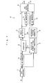
- Fig. 1 is a block diagram of the configuration of a picture angle detection apparatus according to an embodiment of the invention.
- the picture angle detection apparatus 10 shown in Fig. 1 includes line memories 1a, 1b, and 1c, a binarizer 2, an angle detector 3, an arc shape detector 4, a detection window video signal processor 5, a reference pattern generater 6, and an A/D (analog/digital) converter 7.
- the A/D converter 7 converts an analog video signal VA into a digital video signal VD1 for output.
- the video signal VD1 output from the A/D converter 7 is input into the line memory 1a and the binarizer 2 and the detection window video signal processor 5.
- the line memory 1a delays the video signal VD1 output from the A/D converter 7 by one scanning line for output.
- the video signal VD2 thus output from the line memory 1a is provided to the binarizer 2 and the detection window video signal processor 5.
- the video signals VD1 and VD2 have 256 gray scale luminance levels. More specifically, the minimum luminance value for the video signals VD1 and VD2 is "0" and the maximum value is "255".
- the binarizer 2 binarizes the video signal VD1 output from the A/D converter 7 and the video signal VD2 output from the line memory 1a using an average luminance value LU applied from the detection window video signal processor 5 that will be described and outputs a binary pattern BI of "1" and "0".
- the binary pattern BI has a size equal to that of the detection window.
- the detection window is for example a rectangular region including 7 ⁇ 2 pixels, seven pixels of which are from the video signal VD1 and the remaining seven pixels are from the video signal VD2, or a rectangular region including 15 x 2 pixels, 15 pixels of which are from the video signal VD1 and the remaining 15 pixels are from the video signal VD2.
- the size of the detection window is 9 ⁇ 2 pixels.
- the size of the binary pattern BI is also 9 ⁇ 2 pixels.
- the size of the detection window is not limited to these, which can be set arbitrarily within the scope of the invention.
- the detection window video signal processor 5 sets a detection window for the input video signal VD1 and the video signal VD2 output from the line memory 1a, calculates the average luminance value of the video signals VD1 and VD2 in the detection window, and provides the resulting average luminance value LU to the binarizer 2 as a threshold value for binarization.
- the average luminance value of all the pixels in the detection window is used as the threshold for binarization.
- the average value between the maximum and minimum values of the pixels in the detection window or the middle number in the sequence of luminance values in the order of magnitude may be used as the threshold value.
- the average luminance value of a plurality of pixels whose values are close to the middle number in the sequence of luminance values in the order of magnitude may be used as the threshold value for binarization.
- the detection window video signal processor 5 determines whether or not the horizontal luminance distribution of the video signals VD1 and VD2 in the detection window is in the form of a monotonous increase or decrease.
- the minimum value "0" or the maximum value "255” may be provided to the binarizer 2 as a threshold value. Then, the binarizer 2 outputs a binary pattern BI of all "1" or "0".
- the differential value between two adjacent pixels in the video signals VD1 and VD2 may be calculated sequentially, and if the differential values have the same sign, it could be determined that the distribution is in the form of a monotonous increase or decrease.
- the detection window video signal processor 5 calculates the difference between the maximum and minimum luminance values of the video signals VD1 and VD2 in the detection window as a contrast. Then, when the calculated contrast is lower than a prdetermined value, the minimum value "0" or the maximum value "255" is provided to the binarizer 2. In this way, the binarizer 2 outputs a binary pattern BI of all "1" or "0".
- the reference pattern generater 6 generates a plurality of reference patterns RA of "1" and "0" and applies the patterns to the angle detector 3.
- the reference patterns RA each have a size equal to that of the detection window.
- the angle detector 3 compares the binary pattern BI provided from the binarizer 2 with each of the plurality of reference patterns RA provided from the reference pattern generater 6 and outputs the angle of a matched one of the reference patterns RA as angle information S1. The angle will later be described. Now, the comparison operation between the binary pattern BI and the reference patterns RA will be referred to as "pattern matching".
- a binary pattern BI of all "1" or "0" may be output from the binarizer 2.
- the angle information S1 is not output from the angle detector 3.
- the line memory 1b outputs angle information S2 delayed by one scanning line from the angle information S1 output from the angle detector 3 to the arc shape detector 4 and the line memory 1c.
- the line memory 1c applies angle information S3 delayed by one scanning line from the angle information S2 output from the line memory 1b to the arc shape detector 4.
- a scanning line including an interpolation pixel will be referred to as "interpolation scanning line".
- the arc shape detector 4 outputs picture edge angle information T1 based on the combination of the angle information S3 of an interpolation scanning line one line above the object interpolation scanning line, the angle information S1 of an interpolation scanning line one line below the object interpolation scanning line, and the angle information S2 of the object interpolation scanning line.
- the arc shape detector 4 also recognizes the arc shape and outputs arc shape information T2. Note that the angle detection and the arc shape recognition will be detailed later.
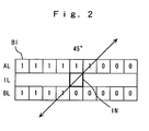
- Fig. 2 is a schematic diagram showing an example of the binary pattern BI output from the binarizer 2 shown in Fig. 1.
- IN represents an interpolation pixel and IL represents an interpolation scanning line.
- AL represents a scanning line one line above the interpolation scanning line IL, while BL represents a scanning line one line below the interpolation scanning line IL.
- the low luminance part (dark part) is indicated by “0” and the high luminance part (bright part) is indicated by “1".
- the angle of the edge of a picture is 45° .
- the horizontal angle is 0 and the angle in the upper right diagonal direction is positive.
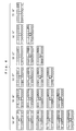
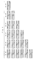
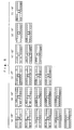
- Figs. 3, 4, 5, and 6 are schematic diagrams each showing an example of reference patterns generated by the reference pattern generater 6 in Fig. 1.
- the shadowed pixels are pixels in the upper and lower scanning lines that are used for calculating values of interpolation pixels indicated by bold squares.
- FIG. 3 (a), (b), (c), (d), (e), and (f) are reference patterns for 45°, 34°, 27°, 22°, 18°, and 16°, respectively.
- the upper left part is a dark part and the lower right part is a bright part.
- Fig. 4 (a), (b), (c), (d), (e), and (f) are reference patterns for 45°, 34°, 27°, 22°, 18°, and 16°, respectively.
- the upper left part is a bright part and the lower right part is a dark part.
- FIG. 5 (a), (b), (c), (d), (e), and (f) are reference patterns for -45°, -34°, -27°, -22°, -18°, and -16°, respectively.
- the upper right part is a dark part and the lower left part is a bright part.
- Fig. 6 (a), (b), (c), (d), (e), and (f) are reference patterns for -45°, -34°, -27°, -22°, -18°, and -16°, respectively.
- the upper right part is a bright part and the lower left part is a dark part.
- the reference patterns shown in Figs. 3 to 6 are compared with the binary pattern BI output from the binarizer 2 at the angle detector 3, and the angle detector 3 outputs the angle information S1 of the reference pattern matched with the pattern BI.
- angles between straight lines connecting pixels located in point-symmetrical positions around the interpolation pixel may be set.
- angles 34° and 22° between 45°, 27°, and 18° can be set.
- the binary pattern BI in Fig. 2 for example can be matched with one of the six reference patterns at (a) in Fig. 4.
- the angle detector 3 in Fig. 1 outputs 45° indicated by the reference pattern at (a) in Fig. 4 as the angle information S1.
- the reference patterns RA generated by the reference pattern generater 6 in Fig. 1 may have an arbitrary size other than those of the examples shown in Fig. 6.
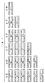
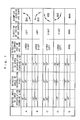
- Fig. 7 is a table for use in illustration of processing by the arc shape detector 4 in Fig. 1.
- the table in Fig. 7 includes detected angles for interpolation pixels, and examples of arc shapes recognized based on combinations of detected angles in a lower interpolation scanning line and an upper interpolation scanning line.
- the arc shapes are divided into five cases of combinations A, B, C, D, and E.
- the edge of the arc (arc edge) has a convex shape directed to the "lower right", and the inside of the arc is directed to the "left".
- the absolute value of the detected angle of the interpolation pixel is the intermediate value between the absolute values of the detected angle in the lower and upper interpolation scanning lines.
- the absolute value of the detected angle in the upper interpolation scanning line is larger than the absolute value of the detected angle in the lower interpolation scanning line and all the detected angles are positive values.
- the arc shape detector 4 outputs the detected angle of the interpolation pixel as angle information T1.
- angle information T1 When an arc shape is recognized, the direction of the inside of the arc shape is output as arc shape information T2.
- Fig. 7 shows schematic arc shapes and the directions of the inside of the arc shapes in the right most column by way of illustration.
- the sets of thin connected arrows are each recognized as an arc, and the direction of each of the thin arrows indicates an angle detected along the arc, and thick arrows indicate the insides of the arcs.
- the direction of the convex shape of the arc edge is the "upper right" and the direction of the inside is the "left".
- the absolute value of the detected angles of the interpolation pixel is the intermediate value between the absolute values of the detected angles in the lower and upper interpolation scanning lines.
- the absolute value of the detected angle in the upper interpolation scanning line is smaller than the absolute value of the detected angle in the lower interpolation scanning line and all the detected angles are negative values.
- the direction of the convex shape of the arc edge is the "upper left” and the direction of the inside of the arc shape is the "right".
- the absolute value of the interpolation pixel is the intermediate value between the absolute values of the detected angles in the lower and upper interpolation scanning lines.
- the absolute value of the detected angle in the upper interpolation scanning line is smaller than the absolute value of the detected angle in the lower interpolation scanning line and all the detected angles are positive values.
- the direction of the convex shape of the arc edge is the "lower left” and the direction of the inside of the arc shape is the "right".
- the absolute value of the detected angle of the interpolation pixel is the intermediate value between the absolute values of the detected angle in the lower and upper interpolation scanning lines.
- the absolute value of the detected angles in the upper interpolation scanning line is smaller than the absolute value of the detected angle in the lower interpolation scanning line and all the detected angles are negative values.
- the intermediate value is defined as any value between two values X and Y, and larger than X and smaller than Y when X ⁇ Y.
- the reference position for a detected angle in the upper interpolation scanning line corresponds to a single point in the direction determined based on the detected angle of the interpolation pixel in the upper interpolation scanning line relative to the interpolation pixel.
- the reference position for the detected angle in the lower interpolation scanning line corresponds to a single point in the direction determined based on the detected angle of the interpolation pixel in the upper interpolation scanning line relative to the interpolation pixel.
- the reference position for a detected angle in the upper interpolation scanning line may be a horizontal region (of a plurality of pixels) having a predetermined width including a point in the direction determined based on the detected angle of the interpolation pixel in the upper interpolation scanning line relative to the interpolation pixel.
- the reference position for a detected angle in the lower interpolation scanning line may be a horizontal region (of a plurality of pixels) having a predetermined width including a point in the direction determined based on the detected angle of the interpolation pixel in the lower interpolation scanning line relative to the interpolation pixel.
- the luminance distribution of the video signals VD1 and VD2 in the detection widow is converted into the binary pattern BI.
- the binary pattern BI is compared for pattern matching with a plurality of preset reference patterns RA, so that the angle of a diagonal edge in a picture can be detected with a small scale circuit configuration.
- the average luminance value in the detection window is used as the threshold value for binarization, and therefore a binary pattern BI including both "0" and "1" can always be produced regardless of the luminance level of the picture and without an externally set binary threshold value.
- the pattern matching is carried out based on the two-dimensional luminance distribution, erroneous detection can be less than the case of using the differential value between two pixels, so that the angle of a diagonal edge of a picture can be detected accurately.
- the angle to be detected is not limited to an angle formed by straight lines connecting pixels in point-symmetry around the interpolation pixel, and angles between these angles can be detected. Consequently, the angles can be detected at smaller intervals using the line memory 1a with a smaller capacity.
- an arc shape can be recognized based on the combination of the detected angle of the interpolation pixel, and the detected angles of the upper and lower interpolation scanning lines, reference patterns that require three or more scanning lines are not necessary. Consequently, the angle of a picture can be detected and the arc shape can be recognized without increasing the circuit scale of the picture angle detection apparatus 10 or the calculation range by the apparatus.
- Fig. 8 is a block diagram showing the configuration of a scanning lines interpolation apparatus including the picture angle detection apparatus shown in Fig. 1.
- the scanning lines interpolation apparatus 100 includes the picture angle detection apparatus 10 and an interpolation circuit 20.
- a video signal VA is input to the picture angle detection apparatus 10 and the interpolation circuit 20.
- the picture angle detection apparatus 10 has the same configuration as that of the picture angle detection apparatus 10 shown in Fig. 1.
- the picture angle detection apparatus 10 detects the angle of a diagonal edge or an arc shape of a picture based on the video signal VA, and outputs angle information T1 and arc shape information T2.
- the interpolation circuit 20 selects pixels from the upper and lower scanning lines in a diagonal direction relative to the interpolation pixel based on the angle information T1 and the arc shape information T2, calculates the luminance value of the interpolation pixel using the luminance values of the selected pixels, and outputs an interpolation video signal VOUT.
- the angles of a picture whose edge in a diagonal direction includes not only a straight line shape but also an arc shape can accurately be detected, and the arc shape can be recognized. Therefore, for the picture whose edge in a diagonal direction includes not only a straight line shape but also an arc shape, suitable pixels in the diagonal direction can be selected to carry out smooth interpolation.
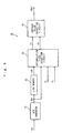
- Fig. 9 is a block diagram of the configuration of the interpolation circuit 20 in the scanning lines interpolation apparatus 100 shown in Fig. 8.
- the interpolation circuit 20 in Fig. 9 includes an A/D (analog/digital) converter 21, a line memory 22, an interpolation pixel selection circuit 23, and an average value operation circuit 24.
- the A/D converter 21 converts an analog video signal VA into a digital video signal VD1 for output.
- the video signal VD1 output from the A/D converter 21 is input into the line memory 22 and the interpolation pixel selection circuit 23.
- the line memory 22 delays the video signal VD1 output from the A/D converter 21 by one scanning line for output.
- the video signal VD2 thus output from the line memory 22 is provided to the interpolation pixel selection circuit 23.
- the interpolation pixel selection circuit 23 selects an interpolation reference pixel P1 from the upper scanning line for output and an interpolation reference pixel P2 from the lower scanning line for output to the average value operation circuit 24.
- the average value operation circuit 24 calculates and outputs the luminance value of the interpolation pixel based on the interpolation reference pixels P1 and P2.
- the interpolation pixel selection circuit 23 selects these interpolation reference pixels so that edges in a picture can be smoothed by interpolation.
- the interpolation pixel selection circuit 23 performs selectively the operation for the case when the picture has a straight line shaped edge and the operation for the case when the picture has an arc shaped edge.
- the interpolation pixel selection circuit 23 selects pixels in the shadowed part in Figs. 3 to 6 from the upper and lower scanning lines as interpolation reference pixels.
- the center positions of the interpolation reference pixels are interpolation reference positions.
- the interpolation pixel selection circuit 23 specifies positions in the direction relative to the interpolation pixel indicated by the angle information T1, and selects positions shifted horizontally within the inside of the arc shape as the interpolation reference positions based on the arc shape information T2.
- the interpolation pixel selection circuit 23 specifies positions in the direction indicated by the angle information T1 in the upper and lower scanning lines relative to the interpolation pixel, and selects the interpolation reference positions from positions shifted to the left from the specified positions.
- the average value operation circuit 24 calculates the average luminance value of the pixels including the interpolation reference positions to determine the luminance value of the interpolation pixel.
- the average value operation circuit 24 includes a correlation operation circuit and may carry out interpolation operation corresponding to the correlation degree, i.e., the difference between the pixels including the interpolation reference positions. In this way, if the angle or arc shape is detected erroneously for some reason, a noise caused by interpolation can be reduced.
- Fig. 10 shows an example of angle information of a picture detected by the picture angle detection apparatus 10 shown in Fig. 1.
- An example of a picture having an arc-shaped edge is shown in Fig. 10.
- Fig. 11 shows an example of interpolation of pixels using the angle information and arc shape information of the picture detected by the picture angle detection apparatus 10 shown in Fig. 1.
- Fig. 12 shows an example of interpolation of pixels using only the angle information of the picture detected by the picture angle detection apparatus 10 shown in Fig. 1.
- IL1, IL2 and IL3 represent interpolation scanning lines.
- AL, BL, CL, and DL represent scanning lines.
- the values on the scanning lines AL, BL, CL, and DL represent the luminance values of the pixels.
- the values on the interpolation scanning lines IL1, IL2, and IL3 are the luminance values of interpolation pixels.
- the values on the IL1, IL2, and IL3 represent the luminance values of the interpolation pixels.
- IN is an interpolation pixel of interest.
- IL2 represents an object interpolation scanning line
- BL is a scanning line above the interpolation scanning line
- CL is a scanning line below the interpolation scanning line
- IL1 is an upper interpolation scanning line
- IL3 is a lower interpolation scanning line.
- the interpolation reference positions P1, P2, P3 and P4 are denoted by x.
- the angle of the object interpolation pixel IN relative to the picture is 27°.
- the positions directed at 27° to the interpolation pixel IN are selected as interpolation reference positions P3 and P4 in the upper and lower scanning lines BL and CL.
- the luminance values of the pixels Q3 and Q4 including interpolation reference positions P3 and P4 are both "100" and therefore the luminance value of the interpolation pixel IN is "100" after interpolation operation using the pixels Q3 and Q4 including the interpolation reference positions P3 and P4.
- the luminance values of the other interpolation pixels are calculated in the same manner, so that the processing result as shown in Fig. 12 is provided.
- R1 and R2 represent reference pixels for the upper and lower interpolation scanning lines IL1 and IL3, respectively.
- the angle information of the reference pixel R1 is 45° and the angle information of the reference pixel R2 is 18°. Therefore, the example in Fig. 11 corresponds to Case A in Fig. 7, and the direction of the inside of the arc shape is the left. Consequently, the positions p1 and p2 at 27° relative to the interpolation pixel IN are specified in the upper and lower scanning lines BL and CL, and the positions 0.5 pixel shifted horizontally to the left from these specified positions p1 and p2 are selected as the interpolation reference positions P1 and P2.
- the luminance values of the pixels including the interpolation positions P1 and P2 are each the average luminance value between the luminance values "100" and "0" of two adjacent pixels Q11 and Q12; Q13 and Q14, in other words, the luminance values are both "50". Therefore, the luminance value of the interpolation pixel IN is "50" after interpolation operation using the pixels including the interpolation reference positions P1 and P2.
- the luminance values of the other interpolation pixels are calculated in the same manner, so that the result as shown in Fig. 11 is provided.
- the values on the interpolation scanning lines IL1, IL2, and IL3 are the luminance values of interpolation pixels, solid circles each represent the intermediate luminance value for each scanning line, and the dotted line connects the points of the intermediate luminance values. More specifically, the dotted line represents the edge of the picture.
- the intermediate value is a luminance value of "50".
- the edge shape of the picture after interpolation is bent when the luminance values of the interpolation pixels are calculated only with the angle information of the picture as shown in Fig. 12 and a smooth edge cannot be provided by the interpolation. More specifically, the interpolation in Fig. 12 is carried out in the locally recognized angle directions, and therefore is not necessarily smooth in terms of overall continuity.
- the interpolation reference positions are shifted by 0.5 pixel when an arc shape is recognized, but the invention is not limited to this, and the shift amount can be set as required.
- the binarizer 2 and the detection window video signal processor 5 correspond to a binary pattern generator, the reference pattern generater 6 to a reference pattern generater and the angle detector 3 to a comparator.
- the arc shape detector 4 corresponds to a shape detector.
- the detection window video signal processor 5 corresponds to a threshold value calculation device and a determination device, and the binarizer 2 corresponds to a binarizer.
Landscapes
- Engineering & Computer Science (AREA)
- Multimedia (AREA)
- Signal Processing (AREA)
- Computer Graphics (AREA)
- Physics & Mathematics (AREA)
- General Physics & Mathematics (AREA)
- Theoretical Computer Science (AREA)
- Image Analysis (AREA)
- Image Processing (AREA)
- Television Systems (AREA)
Applications Claiming Priority (5)
| Application Number | Priority Date | Filing Date | Title |
|---|---|---|---|
| JP2002131230 | 2002-05-07 | ||
| JP2002131230 | 2002-05-07 | ||
| JP2003123406A JP4060748B2 (ja) | 2002-05-07 | 2003-04-28 | 画像角度検出装置それを備えた走査線補間装置 |
| JP2003123406 | 2003-04-28 | ||
| PCT/JP2003/005557 WO2003096689A1 (en) | 2002-05-07 | 2003-04-30 | Image angle detection device and scan line interpolation device having the same |
Publications (2)
| Publication Number | Publication Date |
|---|---|
| EP1534007A1 true EP1534007A1 (de) | 2005-05-25 |
| EP1534007A4 EP1534007A4 (de) | 2010-09-29 |
Family
ID=29422367
Family Applications (1)
| Application Number | Title | Priority Date | Filing Date |
|---|---|---|---|
| EP03720999A Withdrawn EP1534007A4 (de) | 2002-05-07 | 2003-04-30 | Bildwinkeldetektionseinrichtung und scan-linien -interpolationseinrichtung damit |
Country Status (7)
| Country | Link |
|---|---|
| US (1) | US7474354B2 (de) |
| EP (1) | EP1534007A4 (de) |
| JP (1) | JP4060748B2 (de) |
| KR (1) | KR100962801B1 (de) |
| CN (1) | CN100473141C (de) |
| MY (1) | MY141087A (de) |
| WO (1) | WO2003096689A1 (de) |
Cited By (2)
| Publication number | Priority date | Publication date | Assignee | Title |
|---|---|---|---|---|
| WO2008059218A3 (en) * | 2006-11-14 | 2008-08-21 | Sony Uk Ltd | Alias avoidance in image processing |
| US9140541B2 (en) | 2010-08-19 | 2015-09-22 | Mitutoyo Corporation | Image measuring apparatus and image measuring method |
Families Citing this family (20)
| Publication number | Priority date | Publication date | Assignee | Title |
|---|---|---|---|---|
| TWI253848B (en) * | 2004-04-09 | 2006-04-21 | Mstar Semiconductor Inc | Pixel interpolation method and related pixel interpolation device |
| JP2007060512A (ja) * | 2005-08-26 | 2007-03-08 | Pioneer Electronic Corp | 走査線補間回路、該走査線補間回路に用いられる走査線補間方法、及び画像表示装置 |
| US7982798B2 (en) * | 2005-09-08 | 2011-07-19 | Silicon Image, Inc. | Edge detection |
| US8004606B2 (en) * | 2005-09-08 | 2011-08-23 | Silicon Image, Inc. | Original scan line detection |
| US8120703B2 (en) * | 2005-09-08 | 2012-02-21 | Silicon Image/BSTZ | Source-adaptive video deinterlacer |
| GB2431803A (en) * | 2005-10-31 | 2007-05-02 | Sony Uk Ltd | Alias avoidance in image processing |
| JP4870528B2 (ja) * | 2006-11-17 | 2012-02-08 | オリンパス株式会社 | 固体撮像装置 |
| WO2008076566A1 (en) | 2006-12-20 | 2008-06-26 | Anchor Bay Technologies, Inc. | Noise cancellation |
| US8717502B2 (en) | 2007-03-19 | 2014-05-06 | Sony Computer Entertainment Inc. | Methods and apparatuses for upscaling video |
| CN101415103B (zh) * | 2007-10-19 | 2010-08-11 | 英华达(南京)科技有限公司 | 视讯画面的调整方法 |
| US8593572B2 (en) * | 2008-01-30 | 2013-11-26 | Csr Technology Inc. | Video signal motion detection |
| US8559746B2 (en) | 2008-09-04 | 2013-10-15 | Silicon Image, Inc. | System, method, and apparatus for smoothing of edges in images to remove irregularities |
| CN101729882B (zh) * | 2008-10-22 | 2011-06-08 | 矽统科技股份有限公司 | 低角度内插装置及其方法 |
| WO2010093709A2 (en) * | 2009-02-10 | 2010-08-19 | Anchor Bay Technologies, Inc. | Block noise detection and filtering |
| US8154617B2 (en) * | 2009-09-30 | 2012-04-10 | Sony Corporation | Method of detecting the existence of visually sensitive thin lines in a digital image |
| CN102959582B (zh) * | 2010-07-06 | 2015-11-25 | 三菱电机株式会社 | 图像处理装置 |
| JP2012212287A (ja) * | 2011-03-31 | 2012-11-01 | Dainippon Printing Co Ltd | 個体識別装置、個体識別方法、及びプログラム |
| JP2013192094A (ja) * | 2012-03-14 | 2013-09-26 | Toshiba Corp | 映像拡大装置及び映像拡大方法 |
| US9536461B2 (en) | 2014-07-01 | 2017-01-03 | Sony Interactive Entertainment Inc. | Method and system for use in uprendering multimedia content |
| CN115837540A (zh) * | 2021-09-18 | 2023-03-24 | 南通新控自动化设备有限公司 | 焊枪定位方法及装置、桁车 |
Family Cites Families (20)
| Publication number | Priority date | Publication date | Assignee | Title |
|---|---|---|---|---|
| US11708A (en) * | 1854-09-19 | Loren j | ||
| CA1335794C (en) * | 1988-04-07 | 1995-06-06 | Yoshiyuki Okada | Process and apparatus for image magnification |
| JP2732644B2 (ja) | 1989-02-13 | 1998-03-30 | 株式会社東芝 | 相関判定回路 |
| IL98004A (en) * | 1991-04-30 | 1997-02-18 | Scitex Corp Ltd | Apparatus and method for descreening |
| US5347599A (en) | 1991-06-14 | 1994-09-13 | Matsushita Electric Industrial Co., Ltd. | Adaptive interpolation method and apparatus using correlation detection |
| JPH05153562A (ja) | 1991-12-02 | 1993-06-18 | Matsushita Electric Ind Co Ltd | 相関検出補間方法および装置 |
| DE19502997B4 (de) * | 1994-02-01 | 2005-06-30 | Ricoh Co., Ltd. | Einrichtung und Verfahren zum Verarbeiten von Zweiton-Bilddaten |
| US5886745A (en) | 1994-12-09 | 1999-03-23 | Matsushita Electric Industrial Co., Ltd. | Progressive scanning conversion apparatus |
| JPH0937214A (ja) | 1995-07-14 | 1997-02-07 | Matsushita Electric Ind Co Ltd | 順次走査変換方法及び順次走査変換装置 |
| CN1127846C (zh) * | 1995-07-31 | 2003-11-12 | 华邦电子股份有限公司 | 均匀伸缩数字图像尺寸的装置 |
| JPH1141565A (ja) | 1997-07-23 | 1999-02-12 | Sharp Corp | 画像データ補間装置 |
| US6262773B1 (en) * | 1997-09-15 | 2001-07-17 | Sharp Laboratories Of America, Inc. | System for conversion of interlaced video to progressive video using edge correlation |
| JPH11146346A (ja) | 1997-11-13 | 1999-05-28 | Matsushita Electric Ind Co Ltd | 順次走査変換方法及び順次走査変換装置 |
| JPH11175710A (ja) * | 1997-12-16 | 1999-07-02 | Sharp Corp | 画像形成装置 |
| JPH11331773A (ja) | 1998-05-15 | 1999-11-30 | Victor Co Of Japan Ltd | 画像補間方法 |
| US7016539B1 (en) * | 1998-07-13 | 2006-03-21 | Cognex Corporation | Method for fast, robust, multi-dimensional pattern recognition |
| JP2000253238A (ja) * | 1999-03-01 | 2000-09-14 | Mitsubishi Electric Corp | 画像処理装置及び画像処理方法 |
| JP4108969B2 (ja) | 2000-12-14 | 2008-06-25 | 松下電器産業株式会社 | 画像角度検出装置およびそれを備えた走査線補間装置 |
| US7245326B2 (en) * | 2001-11-19 | 2007-07-17 | Matsushita Electric Industrial Co. Ltd. | Method of edge based interpolation |
| US6941016B1 (en) * | 2001-12-31 | 2005-09-06 | Cognex Technology And Investment | Method for finding contours in an image of an object |
-
2003
- 2003-04-28 JP JP2003123406A patent/JP4060748B2/ja not_active Expired - Fee Related
- 2003-04-30 WO PCT/JP2003/005557 patent/WO2003096689A1/ja not_active Ceased
- 2003-04-30 CN CNB038102579A patent/CN100473141C/zh not_active Expired - Fee Related
- 2003-04-30 KR KR1020047017786A patent/KR100962801B1/ko not_active Expired - Fee Related
- 2003-04-30 EP EP03720999A patent/EP1534007A4/de not_active Withdrawn
- 2003-04-30 US US10/509,678 patent/US7474354B2/en not_active Expired - Fee Related
- 2003-05-06 MY MYPI20031704A patent/MY141087A/en unknown
Cited By (3)
| Publication number | Priority date | Publication date | Assignee | Title |
|---|---|---|---|---|
| WO2008059218A3 (en) * | 2006-11-14 | 2008-08-21 | Sony Uk Ltd | Alias avoidance in image processing |
| US8743281B2 (en) | 2006-11-14 | 2014-06-03 | Sony United Kingdom Limited | Alias avoidance in image processing |
| US9140541B2 (en) | 2010-08-19 | 2015-09-22 | Mitutoyo Corporation | Image measuring apparatus and image measuring method |
Also Published As
| Publication number | Publication date |
|---|---|
| EP1534007A4 (de) | 2010-09-29 |
| US7474354B2 (en) | 2009-01-06 |
| CN1653810A (zh) | 2005-08-10 |
| KR20040106470A (ko) | 2004-12-17 |
| MY141087A (en) | 2010-03-15 |
| CN100473141C (zh) | 2009-03-25 |
| JP2004032708A (ja) | 2004-01-29 |
| KR100962801B1 (ko) | 2010-06-09 |
| JP4060748B2 (ja) | 2008-03-12 |
| WO2003096689A1 (en) | 2003-11-20 |
| US20050140664A1 (en) | 2005-06-30 |
Similar Documents
| Publication | Publication Date | Title |
|---|---|---|
| US7474354B2 (en) | Image angle detection device and scan line interpolation device having the same | |
| EP1345432B1 (de) | Scan-zeilen-interpolationseinrichtung | |
| EP1343116B1 (de) | Bildwinkeldetektor und scan-zeilen-interploationseinrichtung | |
| KR100450808B1 (ko) | 정지 판정 장치 및 그것을 구비한 주사선 보간 장치 | |
| KR100335862B1 (ko) | 에지 상관을 사용하여 인터레이스 비디오를 프로그레시브비디오로 변환하는 시스템 | |
| JP2003052023A5 (de) | ||
| JP2003224854A (ja) | 動きベクトル検出装置及び画像処理装置並びにコンピュータ・ソフトウエア | |
| US6930729B2 (en) | Apparatus and method for deleting sawtooth wave | |
| EP1343043A1 (de) | Faradayrotator und optischer abschwächer | |
| JP3216385B2 (ja) | 目標探知追尾装置 | |
| JP2658625B2 (ja) | 補間信号生成回路 | |
| JP2001094951A (ja) | 走査線補間方法 | |
| TWI284478B (en) | Image angle detection device and scan line interpolation device having the same | |
| JPH07146249A (ja) | 欠陥検査装置 | |
| JP2000055830A (ja) | 容器口部検査装置 | |
| JP2005286518A (ja) | 補間信号生成回路 | |
| JP2007142669A (ja) | 走査線補間装置 |
Legal Events
| Date | Code | Title | Description |
|---|---|---|---|
| PUAI | Public reference made under article 153(3) epc to a published international application that has entered the european phase |
Free format text: ORIGINAL CODE: 0009012 |
|
| 17P | Request for examination filed |
Effective date: 20050323 |
|
| AK | Designated contracting states |
Kind code of ref document: A1 Designated state(s): DE FR GB |
|
| RAP1 | Party data changed (applicant data changed or rights of an application transferred) |
Owner name: PANASONIC CORPORATION |
|
| A4 | Supplementary search report drawn up and despatched |
Effective date: 20100830 |
|
| STAA | Information on the status of an ep patent application or granted ep patent |
Free format text: STATUS: THE APPLICATION HAS BEEN WITHDRAWN |
|
| 18W | Application withdrawn |
Effective date: 20130516 |