EP1533888A1 - Dispositif de commande d'inverseur de modulation d'impulsions en largeur et procede de commande associe - Google Patents
Dispositif de commande d'inverseur de modulation d'impulsions en largeur et procede de commande associe Download PDFInfo
- Publication number
- EP1533888A1 EP1533888A1 EP03733290A EP03733290A EP1533888A1 EP 1533888 A1 EP1533888 A1 EP 1533888A1 EP 03733290 A EP03733290 A EP 03733290A EP 03733290 A EP03733290 A EP 03733290A EP 1533888 A1 EP1533888 A1 EP 1533888A1
- Authority
- EP
- European Patent Office
- Prior art keywords
- level
- bus voltage
- reference value
- state
- plus
- Prior art date
- Legal status (The legal status is an assumption and is not a legal conclusion. Google has not performed a legal analysis and makes no representation as to the accuracy of the status listed.)
- Withdrawn
Links
Images


Classifications
-
- H—ELECTRICITY
- H02—GENERATION; CONVERSION OR DISTRIBUTION OF ELECTRIC POWER
- H02M—APPARATUS FOR CONVERSION BETWEEN AC AND AC, BETWEEN AC AND DC, OR BETWEEN DC AND DC, AND FOR USE WITH MAINS OR SIMILAR POWER SUPPLY SYSTEMS; CONVERSION OF DC OR AC INPUT POWER INTO SURGE OUTPUT POWER; CONTROL OR REGULATION THEREOF
- H02M7/00—Conversion of ac power input into dc power output; Conversion of dc power input into ac power output
- H02M7/42—Conversion of dc power input into ac power output without possibility of reversal
- H02M7/44—Conversion of dc power input into ac power output without possibility of reversal by static converters
- H02M7/48—Conversion of dc power input into ac power output without possibility of reversal by static converters using discharge tubes with control electrode or semiconductor devices with control electrode
- H02M7/505—Conversion of dc power input into ac power output without possibility of reversal by static converters using discharge tubes with control electrode or semiconductor devices with control electrode using devices of a thyratron or thyristor type requiring extinguishing means
- H02M7/515—Conversion of dc power input into ac power output without possibility of reversal by static converters using discharge tubes with control electrode or semiconductor devices with control electrode using devices of a thyratron or thyristor type requiring extinguishing means using semiconductor devices only
- H02M7/525—Conversion of dc power input into ac power output without possibility of reversal by static converters using discharge tubes with control electrode or semiconductor devices with control electrode using devices of a thyratron or thyristor type requiring extinguishing means using semiconductor devices only with automatic control of output waveform or frequency
- H02M7/527—Conversion of dc power input into ac power output without possibility of reversal by static converters using discharge tubes with control electrode or semiconductor devices with control electrode using devices of a thyratron or thyristor type requiring extinguishing means using semiconductor devices only with automatic control of output waveform or frequency by pulse width modulation
-
- H—ELECTRICITY
- H02—GENERATION; CONVERSION OR DISTRIBUTION OF ELECTRIC POWER
- H02M—APPARATUS FOR CONVERSION BETWEEN AC AND AC, BETWEEN AC AND DC, OR BETWEEN DC AND DC, AND FOR USE WITH MAINS OR SIMILAR POWER SUPPLY SYSTEMS; CONVERSION OF DC OR AC INPUT POWER INTO SURGE OUTPUT POWER; CONTROL OR REGULATION THEREOF
- H02M7/00—Conversion of ac power input into dc power output; Conversion of dc power input into ac power output
- H02M7/42—Conversion of dc power input into ac power output without possibility of reversal
- H02M7/44—Conversion of dc power input into ac power output without possibility of reversal by static converters
- H02M7/48—Conversion of dc power input into ac power output without possibility of reversal by static converters using discharge tubes with control electrode or semiconductor devices with control electrode
- H02M7/483—Converters with outputs that each can have more than two voltages levels
-
- H—ELECTRICITY
- H02—GENERATION; CONVERSION OR DISTRIBUTION OF ELECTRIC POWER
- H02M—APPARATUS FOR CONVERSION BETWEEN AC AND AC, BETWEEN AC AND DC, OR BETWEEN DC AND DC, AND FOR USE WITH MAINS OR SIMILAR POWER SUPPLY SYSTEMS; CONVERSION OF DC OR AC INPUT POWER INTO SURGE OUTPUT POWER; CONTROL OR REGULATION THEREOF
- H02M1/00—Details of apparatus for conversion
- H02M1/32—Means for protecting converters other than automatic disconnection
-
- H—ELECTRICITY
- H02—GENERATION; CONVERSION OR DISTRIBUTION OF ELECTRIC POWER
- H02M—APPARATUS FOR CONVERSION BETWEEN AC AND AC, BETWEEN AC AND DC, OR BETWEEN DC AND DC, AND FOR USE WITH MAINS OR SIMILAR POWER SUPPLY SYSTEMS; CONVERSION OF DC OR AC INPUT POWER INTO SURGE OUTPUT POWER; CONTROL OR REGULATION THEREOF
- H02M1/00—Details of apparatus for conversion
- H02M1/36—Means for starting or stopping converters
-
- H—ELECTRICITY
- H02—GENERATION; CONVERSION OR DISTRIBUTION OF ELECTRIC POWER
- H02M—APPARATUS FOR CONVERSION BETWEEN AC AND AC, BETWEEN AC AND DC, OR BETWEEN DC AND DC, AND FOR USE WITH MAINS OR SIMILAR POWER SUPPLY SYSTEMS; CONVERSION OF DC OR AC INPUT POWER INTO SURGE OUTPUT POWER; CONTROL OR REGULATION THEREOF
- H02M7/00—Conversion of ac power input into dc power output; Conversion of dc power input into ac power output
- H02M7/42—Conversion of dc power input into ac power output without possibility of reversal
- H02M7/44—Conversion of dc power input into ac power output without possibility of reversal by static converters
- H02M7/48—Conversion of dc power input into ac power output without possibility of reversal by static converters using discharge tubes with control electrode or semiconductor devices with control electrode
- H02M7/483—Converters with outputs that each can have more than two voltages levels
- H02M7/487—Neutral point clamped inverters
Definitions
- the present invention relates to a PWM inverter control apparatus and more particularly to a multilevel PWM inverter control apparatus in which four switching units are connected in series for each layer between a DC bus voltage having a plus level and a DC bus voltage having a minus level.
- a PWM inverter control apparatus In order to control the rotating speed of an AC motor, a PWM inverter control apparatus has widely been used. In the case in which the output current of the PWM inverter control apparatus is increased for some abnormality, it is necessary to limit the output current or to carry out a protecting operation in order to obtain the safety of the PWM inverter control apparatus and the safety of equipment to be connected as a load. In order to implement such a protecting operation, conventionally, the safety has been ensured by using a base block operation for cutting off a gate signal to control ON/OFF of a switching unit and bringing all of the switching units into an OFF state, thereby carrying out a protection.
- Step 41 the output current is detected and a current value thereof is set to be I (Step 41), and the current value I is compared with a preset reference value I th (Step 42).
- Step 42 a normal run is carried out (Step 43) if the current value I is smaller than the reference value I th , and a base block operation is carried out (Step 44) if the current value I is equal to or greater than the reference value I th .
- Step 44 the current value I is compared with the reference value I th in the same manner and the base block operation is continuously carried out until the current value I is smaller than the reference value I th .
- the multilevel PWM inverter control apparatus In the multilevel PWM inverter control apparatus, only a voltage which is a half of the voltage of a DC power supply is applied to both ends of each switching unit. For this reason, the breakdown voltage of each switching unit is a half of the voltage of the DC power supply. When the voltage of the DC power supply is exactly applied to both ends, an overvoltage breakdown is caused. In such a multilevel PWM inverter control apparatus, a large number of switching units are to be switched so that a structure is complicated. Therefore, a problem arises in the case in which the protecting operation is carried out through a base block.
- This problem is that the operation timing of each switching unit is shifted when the normal operation is changed to the base block operation and when the base block operation is changed to the normal operation, and a voltage which is at least a double of a normal voltage is applied to one switching unit, resulting in the generation of the overvoltage breakdown.
- the voltage of the DC power supply is exactly applied to the residual switching unit so that a breakdown is caused.
- JP-A-10-164854 publication there has been proposed a method of detecting an abnormal state when a switching unit is broken down due to a power short circuit or an overcurrent and delaying a timing for cutting off a specific switching unit in order to prevent the further breakdown of the switching unit due to an overvoltage.
- the conventional multilevel PWM inverter control apparatus has the following problems.
- the invention provides a PWM inverter control apparatus in which four switching units are connected in series for each phase between a DC bus voltage having a plus level and a DC bus voltage having a minus level, comprising:
- the base block operation or the emergency stop operation is always carried out after the zero vector state to be started from an 000 state is brought. If the state of the switching unit which is obtained immediately before the execution of a protecting operation is any of P, N and O, therefore, a change in a voltage is reduced to a half of the voltage of a DC power supply so that the switching unit can be prevented from being broken down due to an overvoltage.
- the states of P, N and O are used also in a normal operation. Therefore, it is possible to smoothly carry out a reset from a zero vector state of PPP, 000 or NNN to a normal operation and to perform the protecting operation without requiring a complicated algorithm.
- the controller may carry out a reset to a normal operation after performing a zero vector output operation when executing the reset to the normal operation after carrying out the base block operation.
- a zero vector output operation is always performed. Therefore, it is possible to prevent the switching unit from being broken down due to an overvoltage when carrying out the reset from the protecting operation to the normal operation.
- the invention provides a PWM inverter control apparatus in which four switching units are connected in series for each phase between a DC bus voltage having a plus level and a DC bus voltage having a minus level, comprising:
- setting is carried out to always bring a zero vector state started from an 000 state when performing a reset from the protecting operation to the normal operation. In the switching from the normal operation to the protecting operation and the reset from the protecting operation to the normal operation, therefore, it is possible to prevent the switching unit from being broken down due to an overvoltage.
- the zero vector may be started from an 000 state in which all of the phases are turned ON by the second and third switching units from the DC bus voltage side having the plus level to output the intermediate potential to be the voltage between the plus and minus levels of the DC bus voltage, and may be always brought into the 000 state between a PPP state in which all of the phases are turned ON by first and second switching units from the DC bus voltage side having the plus level to output the plus level of the DC bus voltage and an NNN state in which all of the phases are turned ON by third and fourth switching units from the DC bus voltage side having the plus level to output the minus level of the DC bus voltage.
- 1 denotes a controller
- 2 denotes a current detecting circuit
- 3 denotes a DC power supply
- 41 to 44 denote a step
- 11 and 12 denote a voltage dividing capacitor
- 101 to 112 denote a switching unit
- 201 to 212 denote a free wheel diode
- 301 to 306 denote a clamp diode.
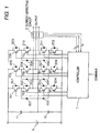
- Fig. 1 is a block diagram showing the structure of a PWM inverter control apparatus according to a first embodiment of the invention.
- the PWM inverter control apparatus is constituted by a controller 1, a current detecting circuit 2, a DC power supply 3, smoothing capacitors 11 and 12, switching units 101 to 112, free wheel diodes 201 to 212, and intermediate level outputting clamp diodes 301 to 306.
- the controller 1 controls a gate signal input to the gate of each of the switching units 101 to 112, thereby controlling the timing of ON/OFF of each of the switching units 101 to 112.
- the current detecting circuit 2 measures the current value of a current output from the PWM inverter control apparatus.
- a positive voltage is output when the switching units 101 and 102 are turned ON
- an intermediate potential is output when the switching units 102 and 103 are turned ON
- a negative voltage is output when the switching units 103 and 104 are turned ON.
- a state in which two upper switching units S1 and S2 are turned ON is represented as a P state in which the plus level of a DC bus voltage is output
- a state in which two middle switching units S2 and S3 are turned ON is represented as an 0 state in which a neutral voltage subjected to capacitor dividing is output
- a state in which two lower switching units S3 and S4 are turned ON is represented as an N state in which the minus level of a DC bus is output.
- the controller 1 brings the state of each phase into a state of P, N or O during a normal operation, thereby controlling an output voltage to a motor.
- the controller 1 controls each switching unit to bring a zero vector state, thereby protecting each switching unit and equipment to be connected.
- the zero vector state implies a state in which the output voltage of each phase is set to have the same level.
- the zero vector state includes three types of states of PPP, 000 and NNN.
- the PWM inverter control apparatus has features in only the control algorithm of the controller 1 and other circuit structures are the same as those in a conventional multilevel PWM inverter control apparatus, detailed description thereof will be omitted.
- an output current is detected by the current detecting circuit 2 and a current value thereof is set to be I (Step 21), and the controller 1 compares the current value I with a first reference value I 1 which is preset (Step 22). If the current value I is smaller than the first reference value I 1 at the Step 22, the controller 1 carries out a normal run (Step 23). If the current value I is equal to or greater than the first reference value I 1 at the Step 22, the controller 1 stops the normal operation and switching to an operation for outputting a zero vector is carried out for a safety.
- the controller 1 switches the vectors of PPP, 000 and NNN in order and outputs them, and sets to always output the zero vector from the 000 when carrying out the switching to the operation for outputting the zero vector.
- the reason is as follows. A pulse pattern obtained immediately before outputting the zero vector cannot be predicted. In the case in which the PPP and the NNN are output at the beginning when the switching to the operation for outputting the zero vector is carried out, therefore, a voltage to be applied to the switching unit is suddenly changed and the ON/OFF timing of the switching unit is varied. Consequently, a full voltage is applied to one switching unit in the worst state, resulting in the breakdown of equipment.
- a voltage is changed from a plus level to a minus level so that a fluctuation in a voltage corresponding to the voltage of the DC power supply 3 is generated when the state of the switching units for the same phase is brought into the N state as a protecting operation.
- a voltage is changed from the minus level to the plus level so that a fluctuation in the voltage corresponding to the voltage of the DC power supply 3 is generated when the states of the switching units for the same phase are brought into the P state as a protecting operation.
- a change in a voltage is a half of the voltage of the DC power supply 3 at a maximum when a state obtained immediately therebefore is any of P, N and O. Even if the ON/OFF timing of the switching unit is varied, thus, only the half of the voltage of the DC power supply 3 is applied to one switching unit.
- the vector of the 000 is set to be output before or after the output of the zero vector of the PPP or NNN, which is safer.
- the controller 1 outputs the zero vector at Step 24 and then compares the output current value I which is detected with a second reference value I 2 (Step 25). If the current value I is smaller than the second reference value I 2 at the Step 25, an operation for outputting the zero vector is continuously carried out (Step 26) and a return to the processing of carrying out a comparison with the first comparison value I 1 is performed (Step 22). If the current value I is smaller than the first reference value I 1 at the Step 22, a reset to the normal run is carried out (Step 23). If the current value I is equal to or greater than the first reference value I 1 , the operation for outputting the zero vector is continuously carried out. If the current value I is equal to or greater than the first reference value I 1 and is smaller than the second reference value I 2 , accordingly, the zero vector is continuously output.
- the controller 1 compares the current value I with a third reference value I 3 (Step 27). If the current value I is smaller than the third reference value I 3 at the Step 27, the controller 1 carries out a base block operation for stopping the operations of all of the switching units 101 to 112 (Step 28). After the processing of the Step 28, then, a return to the processing of comparing the current value I with the second comparison value I 2 is carried out (Step 25) and the same processing as that described above is executed. If the current value I is equal to or greater than the second reference value I 2 , the base block operation is continuously carried out. If the current I is equal to or greater than the second reference value I 2 and is smaller than the third reference value I 3 , accordingly, the controller 1 continuously carries out the base block operation.
- Step 29 In the comparison of the current value I with the third reference value I 3 at the Step 27, if the current value I which is detected is equal to or greater than the third reference value I 3 , the controller 1 stops the operation of the inverter as a final protection and gives an alarm to confirm a whole safety and to carry out restarting (Step 29).
- the controller 1 is set to carry out the base block operation at the Step 28, and thereafter, to always return the normal operation through the operation for outputting the zero vector at the Step 26 without directly performing the reset to the normal operation.
- the first reference value I 1 is set to have a slightly higher level than the level of a rated current value. In other words, while the first reference value I 1 exceeds the rated current value due to a sudden acceleration/deceleration or a fluctuation in a load, it is permitted in a short time. Accordingly, the controller 1 waits for the current value I to be decreased while outputting the zero vector, and returns to the normal operation if the current value I is smaller than the first reference value I 1 .
- the vector itself in the P, N and O states is also output during a normal run. Therefore, this operation can be grasped as a part of the normal run. Therefore, it is possible to smoothly carry out the reset from the protecting operation to the normal run.
- the second reference value I 2 has a higher level than the level of the first reference value I 1 , moreover, it is permitted in a very short time.
- a state in which the current value I is equal to or greater than the second reference value I 2 is generated when an operation exceeding the capability of equipment is to be carried out or due to a sudden change in a load.
- the controller 1 does not bring the zero vector state in which the output current cannot be reduced rapidly but carries out the protecting operation using the base block.
- the third reference value I 3 has a higher level than the level of the second reference value I 2 .
- the current value I is equal to or greater than the third reference value I 3 .
- some abnormality is generated and it is necessary to carry out a release after confirming a safety. Therefore, the equipment itself is not automatically reset. This state will be hereinafter referred to as an emergency stop.
- the first to third reference values I 1 to I 3 are set and the method of the protecting operation is switched depending on the measured current value I in such a manner that a reset to the normal run can be carried out immediately in case of a slight abnormality and the operation can be stopped instantly to ensure the safety in case of a serious abnormality. More specifically, in the case in which a load to be connected to the equipment is operated, it is necessary to meet a demand for safely carrying out a stop operation when some accident is caused without interrupting the run as much as possible.
- the base block operation or the emergency stop operation is always executed after the zero vector state is brought. Setting is carried out to first bring the 000 state in the switching from the normal operation to the zero vector state. Even if the state of the switching unit which is obtained immediately before the execution of the protecting operation is any of P, N and 0, therefore, a change in a voltage is reduced to be a half of the voltage of the DC power supply 3 so that the switching unit can be prevented from being broken down due to an overvoltage.
- the zero vector output operation is always carried out in the execution of the reset from the protecting operation to the normal operation. Therefore, it is possible to prevent the switching unit from being broken down due to an overvoltage in the execution of the reset from the protecting operation to the normal operation.
- the PWM inverter control apparatus is different from the PWM inverter control apparatus according to the first embodiment shown in Fig. 1 in respect of only the control algorithm of a controller 1. In the following, therefore, the operation of the PWM inverter control apparatus according to the embodiment will be described with reference to a flowchart of Fig. 3.
- an output current is detected by a current detecting circuit 2 and a current value thereof is set to be I (Step 31), and the controller 1 compares the current value I with the second reference value I 2 (Step 32). If the current value I is smaller than the second reference value I 2 at the Step 32, the controller 1 carries out a normal run (Step 33). If the current value I is equal to or greater than the second reference value I 2 at the Step 32, the controller 1 stops the normal operation and outputs a zero vector for a safety (Step 34). Herein, the controller 1 may output only an 000 vector in a zero vector. Next, the controller 1 carries out a protecting operation using a base block (Step 35).
- Step 36 the comparison of the current value I and the second reference value I 2 is carried out again. If the current value I is equal to or greater than the reference value I 2 , the base block operation is continuously carried out. If the current value I is smaller than the second reference value I 2 at the Step 36, the controller 1 outputs the zero vector (Step 37) and is thereafter returned to the normal run (the Step 33). In the same manner as in the Step 34, only the 000 vector in the zero vector may be output. By the execution of such a processing, the controller 1 is set to always carry out the operation for outputting the zero vector before a reset from the protecting operation to the normal operation.
- the embodiment supposes an application to a multilevel PWM inverter control apparatus in the case in which a motor connected to equipment having a small number of functions and a simple structure is to be controlled. For this reason, the base block operation is carried out instantly when an overcurrent is simply detected, and the zero vector started from OOO immediately before and after the base block operation is output when a reset from the base block operation to the normal run is to be performed.
- a third reference value I 3 may be provided as a final protection and the inverter may be operated to emergently stop as the final protection or a time required for operating the base block may be integrated and an emergency stop may be carried out after the operation is continuously performed for a certain period or more.
- JP-A-2002-171256 filed on June 12, 2002 and contents thereof are incorporated by reference.
- the multilevel PWM inverter control apparatus it is possible to produce an advantage that switching from a normal operation to a protecting operation can be safely carried out without requiring a complicated control algorithm, and furthermore, the safety of an inverter body can be ensured and a smooth reset from the protecting operation to the normal operation can be performed when the reset is to be executed, and a power can also be supplied safely to equipment to be connected as a load.
Applications Claiming Priority (3)
| Application Number | Priority Date | Filing Date | Title |
|---|---|---|---|
| JP2002171256 | 2002-06-12 | ||
| JP2002171256A JP3864307B2 (ja) | 2002-06-12 | 2002-06-12 | Pwmインバータ制御装置および制御方法 |
| PCT/JP2003/007087 WO2003107521A1 (fr) | 2002-06-12 | 2003-06-04 | Dispositif de commande d'inverseur de modulation d'impulsions en largeur et procede de commande associe |
Publications (2)
| Publication Number | Publication Date |
|---|---|
| EP1533888A1 true EP1533888A1 (fr) | 2005-05-25 |
| EP1533888A4 EP1533888A4 (fr) | 2010-12-22 |
Family
ID=29727799
Family Applications (1)
| Application Number | Title | Priority Date | Filing Date |
|---|---|---|---|
| EP03733290A Withdrawn EP1533888A4 (fr) | 2002-06-12 | 2003-06-04 | Dispositif de commande d'inverseur de modulation d'impulsions en largeur et procede de commande associe |
Country Status (7)
| Country | Link |
|---|---|
| US (1) | US7031172B2 (fr) |
| EP (1) | EP1533888A4 (fr) |
| JP (1) | JP3864307B2 (fr) |
| KR (1) | KR100726536B1 (fr) |
| CN (1) | CN100401629C (fr) |
| TW (1) | TWI281310B (fr) |
| WO (1) | WO2003107521A1 (fr) |
Cited By (2)
| Publication number | Priority date | Publication date | Assignee | Title |
|---|---|---|---|---|
| WO2014004362A3 (fr) * | 2012-06-29 | 2014-11-13 | Eaton Corporation | Appareil d'inverseur multi-niveau et procédés utilisant une réponse de surintensité variable |
| RU2562251C2 (ru) * | 2011-04-01 | 2015-09-10 | Сименс Акциенгезелльшафт | Способ формирования выходного напряжения и устройство для осуществления способа |
Families Citing this family (16)
| Publication number | Priority date | Publication date | Assignee | Title |
|---|---|---|---|---|
| FI116337B (fi) * | 2003-12-19 | 2005-10-31 | Abb Oy | Menetelmä taajuusmuuttajan lähdön virtojen määrittämiseksi |
| US7110272B2 (en) * | 2004-06-22 | 2006-09-19 | Smc Electrical Products, Inc. | Inverter bridge controller implementing short-circuit protection scheme |
| EP1786092A4 (fr) * | 2004-09-02 | 2014-01-15 | Panasonic Corp | Dispositif de commande d'un moteur electrique et climatiseur utilisant ce dispositif |
| KR20070072088A (ko) * | 2005-12-30 | 2007-07-04 | 엘지전자 주식회사 | 인버터 제어장치 및 그 방법 |
| JP5036466B2 (ja) * | 2007-09-20 | 2012-09-26 | 東芝三菱電機産業システム株式会社 | 冗長制御型電力変換システムとその健全性確認方法 |
| US8472223B2 (en) * | 2010-05-12 | 2013-06-25 | Abb Inc. | Bootstrap gate drive for full bridge neutral point clamped inverter |
| JP5163734B2 (ja) * | 2010-12-17 | 2013-03-13 | 富士電機株式会社 | 3レベルインバータ装置 |
| JP6032866B2 (ja) * | 2010-12-22 | 2016-11-30 | 富士電機株式会社 | 電力変換器の制御方法及び制御装置 |
| CN103001573B (zh) * | 2011-09-13 | 2016-03-23 | 台达电子企业管理(上海)有限公司 | 中压变频驱动系统 |
| US20130155738A1 (en) * | 2011-12-19 | 2013-06-20 | General Electric Company | System and method for controlling reactive power in a power conversion system |
| JP5908754B2 (ja) * | 2012-03-13 | 2016-04-26 | シャープ株式会社 | インバータ装置、パワーコンディショナ、及び太陽光発電システム |
| JP5846152B2 (ja) * | 2013-04-15 | 2016-01-20 | 株式会社デンソー | 駆動対象スイッチング素子の駆動回路 |
| RU2556874C1 (ru) * | 2014-03-20 | 2015-07-20 | Федеральное государственное бюджетное образовательное учреждение высшего профессионального образования "Новосибирский государственный технический университет" | Способ управления автономным инвертором |
| RU2558722C1 (ru) * | 2014-04-16 | 2015-08-10 | Федеральное государственное бюджетное образовательное учреждение высшего профессионального образования "Новосибирский государственный технический университет" | Способ управления трехфазным автономным инвертором |
| CN104300816B (zh) * | 2014-08-27 | 2017-01-11 | 中国船舶重工集团公司第七一二研究所 | 一种针对五相三电平变频器的低调制比脉冲输出方法 |
| CN112212460B (zh) * | 2020-08-28 | 2022-03-08 | 海信(山东)空调有限公司 | 一种空调器和停机控制方法 |
Citations (2)
| Publication number | Priority date | Publication date | Assignee | Title |
|---|---|---|---|---|
| JPH07298623A (ja) * | 1994-04-19 | 1995-11-10 | Toshiba Corp | 中性点クランプ式インバータ |
| JPH1132426A (ja) * | 1997-07-09 | 1999-02-02 | Shinko Electric Co Ltd | インバータの保護装置 |
Family Cites Families (7)
| Publication number | Priority date | Publication date | Assignee | Title |
|---|---|---|---|---|
| JPH0767272B2 (ja) * | 1991-02-28 | 1995-07-19 | 株式会社東芝 | 中性点クランプ式電力変換器の制御装置 |
| JP3029305B2 (ja) * | 1991-02-28 | 2000-04-04 | 株式会社東芝 | 中性点クランプ式電力変換器の制御装置 |
| AU651034B2 (en) * | 1992-04-24 | 1994-07-07 | Hitachi Limited | Power converter for converting DC voltage into AC phase voltage having three levels of positive, zero and negative voltage |
| US5790396A (en) * | 1995-12-19 | 1998-08-04 | Kabushiki Kaisha Toshiba | Neutral point clamped (NPC) inverter control system |
| JPH10164854A (ja) * | 1996-11-27 | 1998-06-19 | Hitachi Ltd | 電力変換器 |
| WO2001013504A1 (fr) * | 1999-08-12 | 2001-02-22 | Kabushiki Kaisha Yaskawa Denki | Procede de reglage du potentiel du point neutre d'un onduleur du type a fixation de niveau au point neutre |
| KR100650358B1 (ko) * | 2000-12-07 | 2006-11-27 | 가부시키가이샤 야스카와덴키 | 3레벨 중성점 클램프식 펄스 폭 변조 인버터 장치 및중성점 전압 제어 장치 |
-
2002
- 2002-06-12 JP JP2002171256A patent/JP3864307B2/ja not_active Expired - Lifetime
-
2003
- 2003-06-04 CN CNB038135469A patent/CN100401629C/zh not_active Expired - Lifetime
- 2003-06-04 KR KR1020047018415A patent/KR100726536B1/ko not_active IP Right Cessation
- 2003-06-04 US US10/517,534 patent/US7031172B2/en not_active Expired - Lifetime
- 2003-06-04 EP EP03733290A patent/EP1533888A4/fr not_active Withdrawn
- 2003-06-04 WO PCT/JP2003/007087 patent/WO2003107521A1/fr active Application Filing
- 2003-06-10 TW TW092115720A patent/TWI281310B/zh not_active IP Right Cessation
Patent Citations (2)
| Publication number | Priority date | Publication date | Assignee | Title |
|---|---|---|---|---|
| JPH07298623A (ja) * | 1994-04-19 | 1995-11-10 | Toshiba Corp | 中性点クランプ式インバータ |
| JPH1132426A (ja) * | 1997-07-09 | 1999-02-02 | Shinko Electric Co Ltd | インバータの保護装置 |
Non-Patent Citations (3)
| Title |
|---|
| "VERBESSERUNG DURCH DRITTEN SPANNUNGSPEGEL", ELEKTRONIK, WEKA FACHZEITSCHRIFTENVERLAG, POING, DE, 22 January 2002 (2002-01-22), page 30, XP001050781, ISSN: 0013-5658 * |
| See also references of WO03107521A1 * |
| TADROS Y ET AL: "Three level IGBT inverter", PROCEEDINGS OF THE ANNUAL POWER ELECTRONICS SPECIALISTS CONFERENCE (PESC). TOLEDO, JUNE 29 - JULY 3, 1992; [PROCEEDINGS OF THE ANNUAL POWER ELECTRONICS SPECIALISTS CONFERENCE (PESC)], NEW YORK, IEEE, US, vol. CONF. 23, 29 June 1992 (1992-06-29), pages 46-52, XP010064796, DOI: DOI:10.1109/PESC.1992.254689 ISBN: 978-0-7803-0695-0 * |
Cited By (3)
| Publication number | Priority date | Publication date | Assignee | Title |
|---|---|---|---|---|
| RU2562251C2 (ru) * | 2011-04-01 | 2015-09-10 | Сименс Акциенгезелльшафт | Способ формирования выходного напряжения и устройство для осуществления способа |
| WO2014004362A3 (fr) * | 2012-06-29 | 2014-11-13 | Eaton Corporation | Appareil d'inverseur multi-niveau et procédés utilisant une réponse de surintensité variable |
| US9225262B2 (en) | 2012-06-29 | 2015-12-29 | Eaton Corporation | Multi-level inverter apparatus and methods using variable overcurrent response |
Also Published As
| Publication number | Publication date |
|---|---|
| WO2003107521A1 (fr) | 2003-12-24 |
| KR100726536B1 (ko) | 2007-06-11 |
| TWI281310B (en) | 2007-05-11 |
| JP2004023809A (ja) | 2004-01-22 |
| JP3864307B2 (ja) | 2006-12-27 |
| KR20050008714A (ko) | 2005-01-21 |
| CN100401629C (zh) | 2008-07-09 |
| TW200402187A (en) | 2004-02-01 |
| US7031172B2 (en) | 2006-04-18 |
| US20060056211A1 (en) | 2006-03-16 |
| EP1533888A4 (fr) | 2010-12-22 |
| CN1659776A (zh) | 2005-08-24 |
Similar Documents
| Publication | Publication Date | Title |
|---|---|---|
| US7031172B2 (en) | PMW inverter control apparatus and control method | |
| US9287698B2 (en) | Power conversion apparatus | |
| JP6646086B2 (ja) | Dcリンク部のコンデンサの短絡判定部を有するモータ駆動装置 | |
| CN110710090B (zh) | Dc链路电容器保护 | |
| CN111266876B (zh) | 机床的控制器 | |
| EP1411624B1 (fr) | Onduleur | |
| JP2017225236A (ja) | 電動機駆動装置 | |
| CN108347213B (zh) | 电动机驱动装置 | |
| US11496085B2 (en) | Motor drive apparatus | |
| JP6455938B2 (ja) | 電力変換装置及びその制御方法 | |
| JP4780305B2 (ja) | インバータ装置 | |
| JP2001086751A (ja) | Pwmサイクロコンバータの保護装置とその保護方法 | |
| JPH11122941A (ja) | インバータ装置のアーム短絡検出方法 | |
| KR20090056111A (ko) | 인버터 보호 장치 및 그 방법 | |
| JP3882496B2 (ja) | インバータ装置 | |
| US20230246559A1 (en) | Filter connected to pwm converter and converter system | |
| KR102554512B1 (ko) | 무정전 전원 장치 | |
| JP2019097286A (ja) | 電力変換器の制御回路 | |
| JP2002272181A (ja) | 電力変換装置 | |
| JP2619099B2 (ja) | 可変速運転制御装置 | |
| JPH07337032A (ja) | インバータ制御装置における相電流検出系 | |
| JPH09294379A (ja) | 電力変換器保護装置 | |
| PH12018000166A1 (en) | Motor control apparatus | |
| JP2008029043A (ja) | インバータ電流制限制御 | |
| JPH07107750A (ja) | 電力変換装置 |
Legal Events
| Date | Code | Title | Description |
|---|---|---|---|
| PUAI | Public reference made under article 153(3) epc to a published international application that has entered the european phase |
Free format text: ORIGINAL CODE: 0009012 |
|
| 17P | Request for examination filed |
Effective date: 20041213 |
|
| AK | Designated contracting states |
Kind code of ref document: A1 Designated state(s): AT BE BG CH CY CZ DE DK EE ES FI FR GB GR HU IE IT LI LU MC NL PT RO SE SI SK TR |
|
| RBV | Designated contracting states (corrected) |
Designated state(s): DE FI GB |
|
| A4 | Supplementary search report drawn up and despatched |
Effective date: 20101119 |
|
| STAA | Information on the status of an ep patent application or granted ep patent |
Free format text: STATUS: THE APPLICATION IS DEEMED TO BE WITHDRAWN |
|
| 18D | Application deemed to be withdrawn |
Effective date: 20110218 |