EP1533824A1 - Switch unit capable of directly illuminating switch operating position - Google Patents
Switch unit capable of directly illuminating switch operating position Download PDFInfo
- Publication number
- EP1533824A1 EP1533824A1 EP04255245A EP04255245A EP1533824A1 EP 1533824 A1 EP1533824 A1 EP 1533824A1 EP 04255245 A EP04255245 A EP 04255245A EP 04255245 A EP04255245 A EP 04255245A EP 1533824 A1 EP1533824 A1 EP 1533824A1
- Authority
- EP
- European Patent Office
- Prior art keywords
- sheet member
- switch unit
- light
- emitting part
- conductive polymer
- Prior art date
- Legal status (The legal status is an assumption and is not a legal conclusion. Google has not performed a legal analysis and makes no representation as to the accuracy of the status listed.)
- Withdrawn
Links
Images
Classifications
-
- H—ELECTRICITY
- H01—ELECTRIC ELEMENTS
- H01H—ELECTRIC SWITCHES; RELAYS; SELECTORS; EMERGENCY PROTECTIVE DEVICES
- H01H13/00—Switches having rectilinearly-movable operating part or parts adapted for pushing or pulling in one direction only, e.g. push-button switch
- H01H13/70—Switches having rectilinearly-movable operating part or parts adapted for pushing or pulling in one direction only, e.g. push-button switch having a plurality of operating members associated with different sets of contacts, e.g. keyboard
- H01H13/7006—Switches having rectilinearly-movable operating part or parts adapted for pushing or pulling in one direction only, e.g. push-button switch having a plurality of operating members associated with different sets of contacts, e.g. keyboard comprising a separate movable contact element for each switch site, all other elements being integrated in layers
-
- H—ELECTRICITY
- H01—ELECTRIC ELEMENTS
- H01H—ELECTRIC SWITCHES; RELAYS; SELECTORS; EMERGENCY PROTECTIVE DEVICES
- H01H13/00—Switches having rectilinearly-movable operating part or parts adapted for pushing or pulling in one direction only, e.g. push-button switch
- H01H13/02—Details
-
- H—ELECTRICITY
- H01—ELECTRIC ELEMENTS
- H01H—ELECTRIC SWITCHES; RELAYS; SELECTORS; EMERGENCY PROTECTIVE DEVICES
- H01H9/00—Details of switching devices, not covered by groups H01H1/00 - H01H7/00
- H01H9/16—Indicators for switching condition, e.g. "on" or "off"
-
- H—ELECTRICITY
- H01—ELECTRIC ELEMENTS
- H01H—ELECTRIC SWITCHES; RELAYS; SELECTORS; EMERGENCY PROTECTIVE DEVICES
- H01H2219/00—Legends
- H01H2219/002—Legends replaceable; adaptable
- H01H2219/018—Electroluminescent panel
-
- H—ELECTRICITY
- H01—ELECTRIC ELEMENTS
- H01H—ELECTRIC SWITCHES; RELAYS; SELECTORS; EMERGENCY PROTECTIVE DEVICES
- H01H2219/00—Legends
- H01H2219/036—Light emitting elements
- H01H2219/04—Attachments; Connections
Definitions
- the present invention generally relates to switch units and, more particularly, to a switch unit that illuminates a switch operating position.
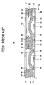
- FIG. 1 shows a conventional switch unit 50 provided with such an illumination function.
- the switch unit 50 generally includes a first sheet member 52 and a second sheet member 53.
- the first sheet member 52 includes a cover sheet 54 and dome movable contacts 55.
- the cover sheet 54 is a sheet made of an insulating resin and has a function of protecting the dome movable contacts 55.
- the dome movable contacts 55 are made of a conductive metal and are formed into dome-like shapes. When pressed, the dome movable contacts 55 elastically move in up and down directions in FIG. 1.
- the first sheet member 52 is provided on a wiring substrate 56, thereby forming push button switches.
- the wiring substrate 56 includes ring fixed contacts 58 and fixed contacts 57 formed in the center positions of the ring fixed contacts 58.
- the outer peripheries of the dome movable contacts 55 are connected to the ring fixed contacts 58.
- the push button switches are formed by the dome movable contacts 55, the fixed contacts 57, and the ring fixed contacts 58.
- the second sheet member 53 includes a plurality of illumination parts 60 formed between a first base member 61 and a second base member 62.
- Each of the illumination parts 60 is formed by a light-emitting part 63 and first and second transparent electrodes 64 and 65 interposing the light-emitting part 63 therebetween.
- the light-emitting part 63 emits light by supplying power thereto from each of the first and second transparent electrodes 64 and 65.
- the first and second transparent electrodes 64 and 65 are formed by an indium-tin oxide (hereinafter referred to as "the ITO") that is transparent and having conductivity.
- the reference numeral 70 designates an air pathway forming spacer.
- the conventional switch unit 50 uses the first and second transparent electrodes 64 and 65 made of the ITO as the electrodes for supplying power to the light-emitting parts 63, there are problems in that the thickness of the second sheet member 53 is increased, which prevents reduction of the thickness of the switch unit 50, and that the positions pressed by a user when using the switch unit 50 cannot be directly illuminated.
- the first and second transparent electrodes 64 and 65 are formed by depositing the ITO on the base members 61 and 62, respectively. It is preferable that the first and second transparent electrodes 64 and 65 have low resistance in terms of ensuring power supply to the light-emitting parts 63 and saving power. In these respects, the ITO has low resistance for a transparent electrode material and is a material having a good electric property.
- the base members 61 and 62 are made of resin such as PET (polyethylene terephthalate), in order to achieve the good electric property of the ITO, it is necessary for the base members 61 and 62 to have a thickness with which the base members 61 and 62 do not warp at the time of deposition. Hence, in the conventional switch unit 50, there is a problem in that the thickness and rigidity of the second sheet member 53 are increased, which results in increases in the thickness and rigidity of the switch unit 50.
- PET polyethylene terephthalate
- the size and thickness of a portable electric device typified by a mobile phone be reduced.
- the increase in the thickness of the switch unit 50 prevents reduction of the size and thickness of a portable electronic device that incorporates the switch unit 50 therein.
- the rigidity of the switch unit 50 is increased. When the rigidity of the switch unit 50 is increased, it becomes difficult or impossible to make the switch unit 50 to be flexibly deformed as a flexible substrate, which causes a problem of poor mounting to the portable electronic device.
- the ITO is a metal oxide (indium-tin oxide) and a thin film
- metal fatigue may occur.
- the transparent electrodes 64 and 65 are not provided directly on the dome movable contacts 55. That is, the first and second transparent electrodes 64 and 65 are provided on the outer peripheries of the dome movable contacts 55.
- a general object of the present invention is to provide an improved and useful switch unit in which one or more of the above-mentioned problems are eliminated.
- Another and more specific object of the present invention is to provide a switch unit capable of directly illuminating a switch operating position while reducing the thickness and rigidity thereof.
- a switch unit including:
- a conductive polymer is more flexible than the conventionally used ITO (indium-tin oxide).
- ITO indium-tin oxide
- a conductive polymer is not formed by deposition.
- the light-emitting part and the movable contact may be arranged to face to each other at least partially.
- the light-emitting part and the movable contact are arranged to face to each other at least partially, a portion subjected to a switch operation by a user is directly illuminated. Hence, it is possible to increase the usability of the switch unit.
- the conductive polymer may be transparent.
- the movable contact may be formed by a dome-like metallic spring.
- the movable contact is formed by a dome-like metallic spring, it is possible to obtain a feeling of clicking caused by deformation of the metallic spring at the time of a switching operation.
- the thickness and rigidity of the second sheet member are reduced by using the conductive polymer as the electrode, it is possible to positively obtain the feeling of clicking.
- the wiring may supply power to the light-emitting part at a position facing the movable contact.
- the switch operating position since power is supplied to the light-emitting part at the position facing the movable contact, which is a light emission position, it is possible to increase brightness at the position of the movable contact (that is, the switch operating position).
- the power supply position since luminous efficiency of the light-emitting part is high at a position where power is supplied, by arranging the power supply position to a position facing the movable contact, it is possible to increase brightness at the position of the movable contact (switch operating position).
- the light-emitting part may be formed to cover substantially an entire surface of the second sheet member.
- a spacer may be provided between the first sheet member and the second sheet member.
- the spacer is provided between the first sheet member and the second sheet member, even if the rigidity of the second sheet member is reduced, it is possible to ensure planarity of the second sheet member in a state where the second sheet member is stacked (provided) on the first sheet member.
- a resin may be supplied to fill in between the first sheet member and the second sheet member so that the first sheet member and the second sheet member constitute an integrated structure.
- the first sheet member and the second sheet member are integrated by the resin, it is possible to position the movable contact provided to the first sheet member and the light-emitting part provided to the second sheet member with good accuracy. Thus, it is possible to positively illuminate the switch operating position.
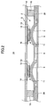
- FIG. 2 shows a switch unit 1A according to one embodiment of the present invention.
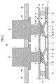
- FIG. 3 shows an electronic device 20 incorporating the switch unit 1A therein.
- the switch unit 1A is added with an illuminating function and used by being incorporated in the electronic device 20 as shown in FIG. 3.
- the switch unit 1A generally includes a first sheet member 2 and a second sheet member 3.
- the first sheet member 2 includes a cover sheet 4, dome movable contacts 5, and an air pathway forming spacer 29.
- the cover sheet 4 is a sheet made of an insulating resin such as polyethylene terephthalate (PET) or polycarbonate, and includes a function of protecting the dome movable contacts 5. Since the dome movable contacts 5 are elastically deformed as mentioned below, a flexible material capable of following such elastic deformation is selected for the dome movable contacts 5.
- the air pathway forming spacer 29 is a sheet having a predetermined thickness (for example, 50 ⁇ m) made of a resin such as polyethylene terephthalate (PET).
- PET polyethylene terephthalate
- the air pathway forming spacer 29 includes an adhesive layer on each of the top surface and the bottom surface thereof.
- the air pathway forming spacer 29 is bonded and fixed to the cover sheet 4 by the adhesive layer on the top surface, and bonded and fixed to a wiring substrate 6 (described below) by the adhesive layer on the bottom surface, thereby forming air pathways connecting spaces between the dome movable contacts 5 (the air pathway forming spacer 29 is hollowed out at regions corresponding to the dome movable contacts 5 and at a pathway pattern, and air pathways are formed by the cover sheet 4 and the wiring substrate 6).
- the dome movable contacts 5 are made of a conductive metal having spring properties or a conductive material (a material obtained by mixing, e.g., carbon in, e.g., rubber) capable of being elastically deformed, and formed into dome shapes.
- the dome movable contacts 5 are elastically deformed by being pressed, and move in the up and down directions in FIG. 2.
- the dome movable contacts 5 and fixed electrodes 27 and 28 (described below) form a push button switch.
- the dome movable contacts 5 When elastically deformed by being pressed as mentioned above, the dome movable contacts 5 generate a feeling of clicking. With the feeling of clicking, it is possible for a user to confirm by the sensation introduced to a finger that a switching operation is positively performed.
- FIG. 2 shows a mode in which the switch unit 1A is shipped after being manufactured.
- a protection tape 6 is applied to the bottom surface of the first sheet member 2.
- the protection sheet 6 is for protecting the dome movable contacts 5 during shipping of the switch unit 1A. Accordingly, the protection sheet 6 is removed when mounting the switch unit 1A to, for example, the electronic device 20.
- the second sheet member 3 is formed by a base member 10 and a plurality of illumination parts 11 formed thereon.
- the base member 10 is a sheet made of a transparent insulating resin such as polyethylene terephthalate (PET) or polycarbonate.
- PET polyethylene terephthalate
- the base member 10 is pressed by the user when operating the switch unit 1A as described below.
- the base member 10 is configured to be flexible.
- Each of the illumination parts 11 is formed by a light-emitting part 12 and a pair of electrodes 13 and 14 (a base electrode 13 and a conductive polymer electrode 14) interposing the light-emitting part 12 therebetween.
- Zinc sulfide (ZnS) doped with copper (Cu) may be used as an illuminator of the light-emitting part 12.
- the illuminator is print formed by, for example, the thick film printing method (for example, screen printing), after being combined with a fluorocarbon resin binder (dissolved into methyl ethyl ketone by using a copolymer of vinylidene fluoride and propylene hexafluoride as a solvent).
- the light-emitting part 12 thus formed emits light by supplying power thereto from the pair of electrodes 13 and 14.
- Each of the base electrodes 13 is formed on a surface of the corresponding one of the light-emitting parts 12, which surface faces the corresponding one of the dome movable contacts 5.
- the base electrode 13 is formed by printing a silver paste on the light-emitting part 12 by using, for example, the thick film printing method, and then vaporizing a binder by a heating process.
- the base electrodes 13 include silver (Ag) as their main constituent, the base electrodes 13 have metallic luster. Hence, the base electrodes 13 also serve as reflectors that reflect light emitted by the light-emitting parts 12. It should be noted that a metal forming the base electrodes 13 is not limited to silver and various conductive materials may be used such as gold, copper, nickel, aluminum, or a conductive polymer combined with, for example, a metal material.
- the conductive polymer electrodes 14 are formed between the light-emitting parts 12 and the base member 10.
- Various materials may be used for the conductive polymer electrodes 14, such as polyacetylene, poly (p-phenylene), polypyrrole, polythiophene, polyaniline, poly-phenylene vinylene, and polyselenophene.
- polyacetylene poly (p-phenylene), polypyrrole, polythiophene, polyaniline, poly-phenylene vinylene, and polyselenophene.
- polypyrrole, polythiophene, or polyaniline having high stability, transparency, and conductivity.
- the conductive polymer electrodes 14 may be formed on the base member 10 by using the thick film printing method.
- the conductive polymer electrodes 14 made of one of the above-mentioned materials are transparent and, since they are polymer, more flexible than the ITO that has been conventionally used. In addition, different from the ITO, the conductive polymer electrodes 14 have low temperature dependency in terms of electric properties. Hence, even if the temperature of the base member 10 is not made high when forming the conductive polymer electrodes 14, it is possible to form the conductive polymer electrodes 14 having low resistance. Further, in the conductive polymer electrodes 14, reduction of electric resistance caused by an increase in the thickness is less. Hence, even if the thicknesses of the conductive polymer electrodes 14 are reduced, it is possible for the electric resistance to be low.
- the sheet resistance value is 200-300 ⁇ /sqr.
- the conductive polymer electrodes 14 As in this embodiment, it is possible to realize 200-300 ⁇ /sqr, which is equivalent to the sheet resistance value of the ITO, with a thickness of 3 ⁇ m.
- the conductive polymer that can be formed by a printing method for the transparent electrodes limitations on the thickness of the base member 10 are eliminated.
- the base member 10 having a thickness of 12 ⁇ m in this embodiment, whereas the thicknesses of the conventional base members 61 and 62 were 100-125 ⁇ m. Since the thickness of the base member 10 can be reduced, the thickness of the second sheet member 3 can also be reduced to a tenth of the conventional thickness.
- the conductive polymer electrodes 14 that do not impose limitations on the base member 10, it is possible to reduce the thickness of the switch unit 1A.
- the conductive polymer electrodes 14 are flexible, and the thickness of the base member 10 can be reduced so as to obtain sufficient flexibility, it is possible to reduce the rigidity of the second sheet member 3 to be low.
- the first sheet member 2 and the second sheet member 3 configured as mentioned above are bonded via first spacers 15.
- the illumination parts 11 are arranged to face the corresponding dome movable contacts 5. That is, in the state where the first sheet member 2 and the second sheet member 3 are bonded, the light-emitting parts 12 and the electrodes 13 and 14 supplying power thereto face the corresponding dome movable contacts 5.
- each light-emitting part 12 may be smaller than, equal to, or larger than the area of the corresponding dome movable contact 5.
- the switch unit 1A thus structured is attached to the electronic device 20 as shown in FIG. 3.
- the first sheet member 2 is arranged on the wiring substrate 26 to form the push button switch.
- the wiring substrate 26 includes ring fixed contacts 28 and fixed contacts 27 formed substantially at the center positions of the ring fixed contacts 28.
- the outer peripheries of the dome movable contacts 5 are connected to the fixed contacts 28.
- the dome movable contact 5 is pressed and moved such that the center portion thereof contacts the fixed contact 27, the fixed contact 27 and the ring fixed contact 28 are electrically connected via the dome movable contact 5.
- the dome movable contacts 5, the fixed contacts 27 and the ring fixed contacts 28 form the push button switch.
- a housing 24 is arranged on the second sheet member 3.
- the housing 24 serves as an exterior case of the electronic device 20 and is made of a hard resin. Additionally, openings 25 are formed in the housing 24 at positions facing the dome movable contacts 5.
- Key tops 22 are formed to project past a top surface of the housing 24 via the openings 25 for a predetermined amount.
- the positions at which the openings 25 are formed correspond to the positions at which the dome movable contacts 5 are formed. Accordingly, when one of the key tops 22 is moved downward by a pressing operation of the key top 22 by the user, the key top 22 presses the corresponding illumination part 11 of the second sheet member 3. As a result, the base member 10 is bent downward, which deforms and bends downward the corresponding light-emitting part 12, base electrode 13, and conductive polymer electrode 14.
- the dome movable contact 5 is elastically deformed, and the center portion thereof contacts the fixed contact 27. Thereby, the fixed contact 27 and the ring fixed contact 28 are electrically connected via the dome movable contact 5.
- the dome movable contact 5 when the dome movable contact 5 is elastically deformed as mentioned above, the dome movable contact 5 generates a feeling of clicking. Thus, the user can determine by the feeling of clicking whether the switch is appropriately operated. Hence, it is possible to improve the operability of the electronic device 20. It should be noted that, when the pressing operation with respect to the key top 22 is cancelled, the key top 22 moves upward to the position before the pressing operation mainly by elastic restoration forces of the dome movable contact 5 and the second sheet member 3.
- the power supply is started when a cover part is opened with respect to a mobile phone body having the key tops 22 arranged thereon.
- the light-emitting parts 12 emit light to illuminate the key tops 22.
- the conductive polymer electrodes 14 are transparent, the color of the light emitted by the light-emitting parts 12 can be supplied toward the key tops 22 as it is without being affected by the conductive polymer electrodes 14.
- the base member 10 and the key tops 22 are also transparent, the user of the electronic device 20 can see the light from the light-emitting parts 12 via the key tops 22, the base member 10, and the conductive polymer electrodes 14.
- the switch unit 1A since the switch unit 1A according to this embodiment uses the conductive polymer electrodes 14, it is possible to arrange each of the electrodes 13 and 14 to the position facing the corresponding dome movable contact 5. Thus, it is possible to supply power to the light-emitting parts 12 at the positions facing the dome movable contacts 5.
- the luminous efficiency of the light-emitting parts 12 is high at power supplying positions.
- the conductive polymer electrodes 14 are more flexible than the conventionally used ITO (indium-tin oxide) and do not impose limitations on the thickness of the base member 10. Hence, it is possible for the light-emitting parts 12 to emit high-intensity light without variation while reducing the thickness and rigidity of the second sheet member 3. Accordingly, it is possible to improve the usability of the key tops 22 while reducing the size and thickness of the electronic device 20.
- ITO indium-tin oxide
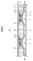
- FIG. 4 shows a switch unit 1B according to a variation of the above-mentioned switch unit 1A.
- those parts that are the same as those corresponding parts in FIGS. 2 and 3 are designated by the same reference numerals, and a description thereof is omitted.
- a resin 40 is provided (is supplied to fill in) between the first sheet member 2 and the second sheet member 3, thereby integrally forming the first sheet member 2 and the second sheet member 3.
- the resin 40 may be formed by a method (injection molding) in which the resin 40 is poured into a metal mold after attaching the first sheet member 2 and the second sheet member 3 inside the metal mold.
- the first sheet member 2 and the second sheet member 3 are integrally formed. Hence, it is possible to position the dome movable contacts 5 provided to the first sheet member 2 and the light-emitting parts 12 (illumination parts 11) provided to the second sheet member 3 with good accuracy. Thus, it is possible for the illumination parts 11 to directly and positively illuminate the switch operating positions (the positions at which the key tops 22 are provided).
- each light-emitting part 12 may be smaller than, equal to, or larger than the area of the corresponding dome movable contact 5 (the light emitting parts are formed in the vicinities of the dome movable contacts 5).
- the light-emitting parts 12 may be formed over substantially an entire surface of the second sheet member 3. With such a structure, it is possible to illuminate substantially the entire surface (wide area) of the second sheet member 3 while reducing the thickness and rigidity of the switch unit (1A, 1B).
Landscapes
- Push-Button Switches (AREA)
- Switch Cases, Indication, And Locking (AREA)
Applications Claiming Priority (2)
| Application Number | Priority Date | Filing Date | Title |
|---|---|---|---|
| JP2003389712A JP2005150034A (ja) | 2003-11-19 | 2003-11-19 | スイッチユニット |
| JP2003389712 | 2003-11-19 |
Publications (1)
| Publication Number | Publication Date |
|---|---|
| EP1533824A1 true EP1533824A1 (en) | 2005-05-25 |
Family
ID=34431582
Family Applications (1)
| Application Number | Title | Priority Date | Filing Date |
|---|---|---|---|
| EP04255245A Withdrawn EP1533824A1 (en) | 2003-11-19 | 2004-08-31 | Switch unit capable of directly illuminating switch operating position |
Country Status (5)
| Country | Link |
|---|---|
| US (1) | US7015408B2 (ja) |
| EP (1) | EP1533824A1 (ja) |
| JP (1) | JP2005150034A (ja) |
| KR (1) | KR20050048457A (ja) |
| CN (1) | CN1619733A (ja) |
Cited By (1)
| Publication number | Priority date | Publication date | Assignee | Title |
|---|---|---|---|---|
| FR2891636A1 (fr) * | 2005-09-30 | 2007-04-06 | Itt Mfg Enterprises Inc | Ensemble de clavier pour un appareil electronique portable et appareil equipe d'un tel clavier |
Families Citing this family (26)
| Publication number | Priority date | Publication date | Assignee | Title |
|---|---|---|---|---|
| JP4374895B2 (ja) * | 2003-05-09 | 2009-12-02 | 富士ゼロックス株式会社 | 画像形成装置 |
| JP4305212B2 (ja) * | 2004-02-18 | 2009-07-29 | 日本電気株式会社 | 携帯電話機及びその製造方法 |
| KR100629053B1 (ko) * | 2005-05-19 | 2006-09-26 | 삼성전자주식회사 | 키 패드 어셈블리 |
| KR100877067B1 (ko) * | 2006-01-03 | 2009-01-07 | 삼성전자주식회사 | 햅틱 버튼 및 이를 이용한 햅틱 기기 |
| JP4802724B2 (ja) * | 2006-01-18 | 2011-10-26 | パナソニック株式会社 | 入力装置 |
| JP2007242274A (ja) | 2006-03-06 | 2007-09-20 | Alps Electric Co Ltd | 照光機能付き接点シート及びこれを用いた入力装置 |
| KR100676480B1 (ko) * | 2006-04-25 | 2007-02-02 | 주식회사 케이비에프 | 도광판과 일체화된 휴대폰 키패드의 인쇄회로기판 |
| KR100780323B1 (ko) * | 2006-06-27 | 2007-11-29 | 한국오므론전장주식회사 | 시트형상 조명 스위치 |
| JP2008016310A (ja) * | 2006-07-06 | 2008-01-24 | Matsushita Electric Ind Co Ltd | 可動接点体 |
| JP4926762B2 (ja) * | 2006-08-03 | 2012-05-09 | シチズン電子株式会社 | 発光シートモジュール |
| KR101243669B1 (ko) * | 2006-10-18 | 2013-03-25 | 엘지전자 주식회사 | 휴대 단말기 |
| JP2008204769A (ja) * | 2007-02-20 | 2008-09-04 | Matsushita Electric Ind Co Ltd | 導光シート及びこれを用いた可動接点体とスイッチ |
| JP2008310556A (ja) * | 2007-06-14 | 2008-12-25 | Panasonic Corp | 入力装置およびその入力装置用モジュール品の製造方法 |
| JP2008311162A (ja) * | 2007-06-18 | 2008-12-25 | Panasonic Corp | スイッチ |
| US7718910B2 (en) * | 2007-06-20 | 2010-05-18 | Panasonic Corporation | Movable contact assembly and switch using the same |
| KR100843263B1 (ko) * | 2007-06-28 | 2008-07-02 | (주)지엔씨 | 키 입력장치 |
| DE102007052849A1 (de) * | 2007-11-06 | 2009-05-20 | Trw Automotive Safety Systems Gmbh | Teilweise verchrombare Vorrichtung und Verfahren zu deren Herstellung |
| US7435922B1 (en) * | 2007-12-13 | 2008-10-14 | Animas Corporation | Over-molded keypad and method of manufacture |
| US8164015B2 (en) * | 2008-02-28 | 2012-04-24 | Panasonic Corporation | Movable contact unit and switch using the same |
| JP2009205940A (ja) * | 2008-02-28 | 2009-09-10 | Panasonic Corp | 導光シート及びこれを用いた可動接点体 |
| US20100038226A1 (en) * | 2008-08-18 | 2010-02-18 | Hung Lin | Illuminated keyboard module |
| JP2011222379A (ja) * | 2010-04-13 | 2011-11-04 | Alps Electric Co Ltd | 導光シート、接点ばね付きシート及びスイッチ装置 |
| TWM460386U (zh) * | 2013-03-20 | 2013-08-21 | Darfon Electronics Corp | 雙膜片開關以及使用此雙膜片開關之連接座 |
| US9810401B2 (en) * | 2013-11-21 | 2017-11-07 | Ford Global Technologies, Llc | Luminescent trim light assembly |
| CN104299832B (zh) * | 2014-10-15 | 2016-06-22 | 京东方科技集团股份有限公司 | 发光按键 |
| TWI556279B (zh) * | 2015-03-27 | 2016-11-01 | 致伸科技股份有限公司 | 發光鍵盤裝置 |
Citations (6)
| Publication number | Priority date | Publication date | Assignee | Title |
|---|---|---|---|---|
| US4558427A (en) * | 1982-03-03 | 1985-12-10 | Casio Computer Co., Ltd. | Sheet-like compact electronic equipment |
| US20020030987A1 (en) * | 2000-08-08 | 2002-03-14 | Atsushi Saito | Light illuminating type switch |
| WO2002097837A1 (fr) | 2001-05-25 | 2002-12-05 | Shin-Etsu Polymer Co., Ltd. | Element pour commutateur a bouton-poussoir et son procede de fabrication |
| JP2002367469A (ja) * | 2001-06-11 | 2002-12-20 | Shin Etsu Polymer Co Ltd | 押釦スイッチ用部材とその製造方法 |
| US20030041443A1 (en) * | 2001-08-30 | 2003-03-06 | Novatech Electroluminescent, Inc. | Method for manufacturing low cost electroluminescent (EL) illuminated membrane switches |
| US20030112620A1 (en) * | 2000-06-08 | 2003-06-19 | Prindle Rick D. | Method and apparatus for illuminating a keypad |
Family Cites Families (8)
| Publication number | Priority date | Publication date | Assignee | Title |
|---|---|---|---|---|
| US5691716A (en) * | 1993-07-29 | 1997-11-25 | Crowley; Robert J. | Keyboard with keys for moving cursor |
| JPH0935571A (ja) * | 1995-07-14 | 1997-02-07 | Matsushita Electric Ind Co Ltd | 照光式スイッチユニット |
| JP3244025B2 (ja) * | 1996-12-05 | 2002-01-07 | 三菱電機株式会社 | 照光スイッチ用照明装置及びその製造方法 |
| JP4038265B2 (ja) * | 1998-02-17 | 2008-01-23 | セイコープレシジョン株式会社 | El付きシートスイッチ |
| US6765503B1 (en) * | 1998-11-13 | 2004-07-20 | Lightpath Technologies, Inc. | Backlighting for computer keyboard |
| US6803903B1 (en) * | 2000-08-17 | 2004-10-12 | Nokia Mobile Phones, Ltd. | Integration of organic light-emitting components into the keyboard of an electronic device |
| JP2003067114A (ja) * | 2001-08-24 | 2003-03-07 | Matsushita Electric Ind Co Ltd | 照光装置 |
| JP2003077366A (ja) | 2001-09-05 | 2003-03-14 | Seiko Precision Inc | スイッチユニット |
-
2003
- 2003-11-19 JP JP2003389712A patent/JP2005150034A/ja active Pending
-
2004
- 2004-08-06 KR KR1020040062041A patent/KR20050048457A/ko not_active Application Discontinuation
- 2004-08-30 US US10/929,534 patent/US7015408B2/en not_active Expired - Fee Related
- 2004-08-31 CN CNA2004100740479A patent/CN1619733A/zh active Pending
- 2004-08-31 EP EP04255245A patent/EP1533824A1/en not_active Withdrawn
Patent Citations (7)
| Publication number | Priority date | Publication date | Assignee | Title |
|---|---|---|---|---|
| US4558427A (en) * | 1982-03-03 | 1985-12-10 | Casio Computer Co., Ltd. | Sheet-like compact electronic equipment |
| US20030112620A1 (en) * | 2000-06-08 | 2003-06-19 | Prindle Rick D. | Method and apparatus for illuminating a keypad |
| US20020030987A1 (en) * | 2000-08-08 | 2002-03-14 | Atsushi Saito | Light illuminating type switch |
| WO2002097837A1 (fr) | 2001-05-25 | 2002-12-05 | Shin-Etsu Polymer Co., Ltd. | Element pour commutateur a bouton-poussoir et son procede de fabrication |
| EP1398808A1 (en) * | 2001-05-25 | 2004-03-17 | Shin-Etsu Polymer Co., Ltd. | Member for push button switch and method for manufacturing the same |
| JP2002367469A (ja) * | 2001-06-11 | 2002-12-20 | Shin Etsu Polymer Co Ltd | 押釦スイッチ用部材とその製造方法 |
| US20030041443A1 (en) * | 2001-08-30 | 2003-03-06 | Novatech Electroluminescent, Inc. | Method for manufacturing low cost electroluminescent (EL) illuminated membrane switches |
Cited By (1)
| Publication number | Priority date | Publication date | Assignee | Title |
|---|---|---|---|---|
| FR2891636A1 (fr) * | 2005-09-30 | 2007-04-06 | Itt Mfg Enterprises Inc | Ensemble de clavier pour un appareil electronique portable et appareil equipe d'un tel clavier |
Also Published As
| Publication number | Publication date |
|---|---|
| CN1619733A (zh) | 2005-05-25 |
| US20050103610A1 (en) | 2005-05-19 |
| KR20050048457A (ko) | 2005-05-24 |
| JP2005150034A (ja) | 2005-06-09 |
| US7015408B2 (en) | 2006-03-21 |
Similar Documents
| Publication | Publication Date | Title |
|---|---|---|
| US7015408B2 (en) | Switch unit capable of directly illuminating switch operating position | |
| US6373008B1 (en) | Light illuminating type switch | |
| EP1039493B1 (en) | El-combined sheet switch | |
| US7723627B2 (en) | EL sheet and member for lighting push-button switch | |
| JP2008204769A (ja) | 導光シート及びこれを用いた可動接点体とスイッチ | |
| US7705256B2 (en) | Thin key sheet | |
| JP2004014284A (ja) | 照光スイッチシート及びこれを用いた照光ユニット | |
| CN100527910C (zh) | 发光电子元件 | |
| KR100514759B1 (ko) | 초박형 발광 키패드 | |
| JP4020777B2 (ja) | 照光式押釦スイッチ用部材 | |
| KR100583353B1 (ko) | 전도성 고분자로 구성된 전면전극층 및 배면전극층을 포함한 무기 el 램프, 상기 무기 el 램프를 이용한 키패드 및 그의 제조방법 | |
| KR200325934Y1 (ko) | 이엘 돔 테이프 키패드 | |
| JP4342880B2 (ja) | キーパッド及びその製造方法 | |
| JPH1139984A (ja) | El照光式スイッチ | |
| KR20060116057A (ko) | 이엘 램프시트 및 그의 제조 방법 | |
| KR100705483B1 (ko) | 발광 키패드 | |
| KR200426230Y1 (ko) | 발광 키패드 | |
| JP2004213924A (ja) | 照光式押釦スイッチ用部材及び携帯電話の照光式押釦スイッチ用部材 | |
| JP4527628B2 (ja) | 押釦スイッチ用カバー部材 | |
| JP4584046B2 (ja) | キーパッド | |
| KR20070000996A (ko) | 가동 접점체 및 그 제조 방법 | |
| JP4606717B2 (ja) | El一体成形体 | |
| JP4944447B2 (ja) | 操作パネル | |
| KR100817142B1 (ko) | 플렉시블 이엘 시트 일체형 키패드 및 그 제조 방법 | |
| WO2006059834A1 (en) | Super thin type light emitting keypad |
Legal Events
| Date | Code | Title | Description |
|---|---|---|---|
| PUAI | Public reference made under article 153(3) epc to a published international application that has entered the european phase |
Free format text: ORIGINAL CODE: 0009012 |
|
| AK | Designated contracting states |
Kind code of ref document: A1 Designated state(s): AT BE BG CH CY CZ DE DK EE ES FI FR GB GR HU IE IT LI LU MC NL PL PT RO SE SI SK TR |
|
| AX | Request for extension of the european patent |
Extension state: AL HR LT LV MK |
|
| 17P | Request for examination filed |
Effective date: 20050517 |
|
| AKX | Designation fees paid |
Designated state(s): DE FR GB |
|
| GRAP | Despatch of communication of intention to grant a patent |
Free format text: ORIGINAL CODE: EPIDOSNIGR1 |
|
| GRAS | Grant fee paid |
Free format text: ORIGINAL CODE: EPIDOSNIGR3 |
|
| STAA | Information on the status of an ep patent application or granted ep patent |
Free format text: STATUS: THE APPLICATION IS DEEMED TO BE WITHDRAWN |
|
| 18D | Application deemed to be withdrawn |
Effective date: 20100302 |