EP1533630B1 - Sicherheits-Lichtgitter - Google Patents
Sicherheits-Lichtgitter Download PDFInfo
- Publication number
- EP1533630B1 EP1533630B1 EP04023321A EP04023321A EP1533630B1 EP 1533630 B1 EP1533630 B1 EP 1533630B1 EP 04023321 A EP04023321 A EP 04023321A EP 04023321 A EP04023321 A EP 04023321A EP 1533630 B1 EP1533630 B1 EP 1533630B1
- Authority
- EP
- European Patent Office
- Prior art keywords
- light
- configuration
- input elements
- input
- light grid
- Prior art date
- Legal status (The legal status is an assumption and is not a legal conclusion. Google has not performed a legal analysis and makes no representation as to the accuracy of the status listed.)
- Expired - Lifetime
Links
- 230000004913 activation Effects 0.000 claims abstract description 9
- 238000011156 evaluation Methods 0.000 claims description 15
- 230000004888 barrier function Effects 0.000 claims description 11
- 230000009849 deactivation Effects 0.000 claims description 6
- 238000012544 monitoring process Methods 0.000 claims description 6
- 230000008859 change Effects 0.000 claims description 4
- 230000003287 optical effect Effects 0.000 abstract description 5
- 230000035945 sensitivity Effects 0.000 abstract 1
- 238000001994 activation Methods 0.000 description 6
- 230000001681 protective effect Effects 0.000 description 6
- 238000003825 pressing Methods 0.000 description 4
- 238000004891 communication Methods 0.000 description 2
- 238000010276 construction Methods 0.000 description 2
- 238000013461 design Methods 0.000 description 2
- 238000000034 method Methods 0.000 description 2
- 230000003213 activating effect Effects 0.000 description 1
- 238000005452 bending Methods 0.000 description 1
- 230000008901 benefit Effects 0.000 description 1
- 238000005520 cutting process Methods 0.000 description 1
- 238000010586 diagram Methods 0.000 description 1
- 230000009977 dual effect Effects 0.000 description 1
- 238000005516 engineering process Methods 0.000 description 1
- 231100001261 hazardous Toxicity 0.000 description 1
- 230000008569 process Effects 0.000 description 1
- 238000004080 punching Methods 0.000 description 1
- 230000003068 static effect Effects 0.000 description 1
- 230000001360 synchronised effect Effects 0.000 description 1
- 238000003466 welding Methods 0.000 description 1
Images
Classifications
-
- F—MECHANICAL ENGINEERING; LIGHTING; HEATING; WEAPONS; BLASTING
- F16—ENGINEERING ELEMENTS AND UNITS; GENERAL MEASURES FOR PRODUCING AND MAINTAINING EFFECTIVE FUNCTIONING OF MACHINES OR INSTALLATIONS; THERMAL INSULATION IN GENERAL
- F16P—SAFETY DEVICES IN GENERAL; SAFETY DEVICES FOR PRESSES
- F16P3/00—Safety devices acting in conjunction with the control or operation of a machine; Control arrangements requiring the simultaneous use of two or more parts of the body
- F16P3/12—Safety devices acting in conjunction with the control or operation of a machine; Control arrangements requiring the simultaneous use of two or more parts of the body with means, e.g. feelers, which in case of the presence of a body part of a person in or near the danger zone influence the control or operation of the machine
- F16P3/14—Safety devices acting in conjunction with the control or operation of a machine; Control arrangements requiring the simultaneous use of two or more parts of the body with means, e.g. feelers, which in case of the presence of a body part of a person in or near the danger zone influence the control or operation of the machine the means being photocells or other devices sensitive without mechanical contact
- F16P3/144—Safety devices acting in conjunction with the control or operation of a machine; Control arrangements requiring the simultaneous use of two or more parts of the body with means, e.g. feelers, which in case of the presence of a body part of a person in or near the danger zone influence the control or operation of the machine the means being photocells or other devices sensitive without mechanical contact using light grids
Definitions
- the invention relates to a safety light grid for monitoring a protective field according to the preamble of claim 1.
- Such light grids for safety technology are used, for example, for safeguarding dangerous machines, such as press bending presses, punching machines, cutting tools, welding robots and the like.
- the safety light curtain protects against inadmissible intrusion into hazardous areas by monitoring the protective field created by the light grid for damage by an object. If the protective field is violated, the safety light grid emits a corresponding signal that z. B. can trigger a shutdown of the dangerous machine.
- Light grids are known in which the configuration data are set by means of wire bridges on the light grid itself or on an associated control unit. This is not only time-consuming and labor-intensive, but certain procedures must be set in the device so that in a simple error, such as wire break, the set function does not change unintentionally. This configuration type therefore carries a security risk and is not very comfortable.
- DIP switches for configuration are known, but have the disadvantage that they can only be operated by a person skilled in the art and that are arranged inside the device. To set it is therefore always necessary to open the device.
- safety light grids are known in which the configuration can be set via a graphical user interface.
- An accessory such as a PC and a device communication interface must be provided.
- a light curtain is known with a number of photocells which can be switched off to transport certain workpieces through the light curtain without generating a shutdown signal.
- an input device is provided, which consists of a plurality of keys, which is divided into a horizontal and vertical number key row with the numbers 0 to 9. The horizontal and vertical number key rows are assigned to the horizontal and vertical photocells of the receiver strips. A dimension of a workpiece determined in centimeters can now be entered for the horizontal and vertical dimension using the keys and starting from a central center, the respective photocells are deactivated.
- a display device is provided for indicating a turn-on state of the light curtain.
- a safety device known from two light strips are arranged on the command buttons.
- the two light strips are arranged on a first side and on an opposite side, a mirror arrangement is mounted to redirect individual light rays starting from individual transmitting elements on individual receiving elements of the light strips. In this case, only the side with the light strips needs to be formed with command buttons.
- a distance sensor which operates on the triangulation principle, with different keys, each with special functions.
- a selection, setting, setting button is provided as a multifunction button. This button selects various functions. After selecting a function, the values displayed for this purpose are changed in their values via an adjustment button. If the multifunction button is then pressed permanently for a long time, the selected value is set and saved as an operating parameter. Furthermore, the multifunction button has the function of a teach-in button, after which, for example, a detected distance of the sensor is taken over and learned.
- the aforementioned setting options such as, for example, an object position or a threshold setting, are in each case analogous setting options which permit a multiplicity of different values. To display the different values, for example a distance range, a multi-digit display device is required.
- a multibeam light barrier comprising individual display elements for indicating a status of a single beam and display elements for indicating whether a respective beam has been interrupted by an object.
- the display elements can each be assigned to a group of optical beams via a button. By repeatedly pressing the button, the groups of optical beams are successively displayed on the display elements.
- the present invention seeks to provide a light grid of the type specified, which is simple and inexpensive to configure.
- the safety light grid according to the invention for monitoring a protective field has a light emitting strip and a light receiving strip, so that a multiplicity of light barriers forming parallel to one another and forming the protective field are formed.
- a warning signal can be derived when one or more light barriers are interrupted by an object.
- the configuration means are formed by two input elements and at least one display element, wherein for activating a configuration mode, both input elements can be actuated simultaneously.
- the configuration parameters include activation or deactivation of a contactor control, activation or deactivation of a restart interlock, high or low range, selection of a signal for System connected to a diagnostic output and / or selection of one of several muting times.
- the control and evaluation unit is designed in such a way that the input of the configuration parameters via the input elements takes place in a fail-safe manner, wherein a holding of an input element or a wrong sequence of input element actuations can be recognized by the control and evaluation unit and does not lead to a configuration change.
- the essential advantage of the invention is that the input of the configuration data on the one hand very simple, fast and convenient via only two input elements and on the other hand that no additional devices, such as PC, device communication interface or the like, are required. Simple functions can be selected and deselected or offer a choice. These are not complex or varied settings.
- the inventive construction is correspondingly inexpensive. In order to activate the configuration mode fail-safe, both input elements can be actuated simultaneously.
- control and evaluation unit is designed such that the input of configuration data via the input elements is fail-safe. This means that a static signal on one of the input elements, eg. B. by holding a button or a wrong operation of the input elements by the control and evaluation is recognizable and does not lead to a configuration change.
- buttons are also very easy to use.
- seven-segment displays are used in light grids for displaying operating states, so that advantageously one can also be used for the display of configuration parameters.
- the configuration means are integrated in the light receiving bar. This can save additional equipment.
- one of the input elements is designed to select a function and the other to select the selected function.
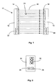
- a light grating 10 has a light emitting strip 12, which has a row of light emitters 14 arranged side by side, and a light receiving strip 16, which has the light emitters 18, which are likewise arranged next to one another, corresponding to the light emitters 14.
- Each opposite light emitter 14 and light receiver 18 form in a known manner a plurality of mutually parallel photocells 20, the light beam is shown in Fig. 1 by dashed lines.
- the light grid 10 with its light barriers 20 thus defines between the transmitting strip 12 and the receiving strip 16 a monitoring area with a protective field 21.
- the light grid 10 furthermore has at least one control and evaluation unit. In the illustrated embodiment, at least one respective control and evaluation unit 22 or 24 is provided both in the transmitting 12 and in the receiving bar 16.
- the control and evaluation unit 22 controls the individual light emitter 14 of Transmit bar 12 and the control and evaluation unit 24 of the reception bar controls the light receiver 18 and evaluates their signals, so that when interrupted one or more light barriers 20 by an object a warning signal from the control and evaluation unit 24 can be derived. This signal can also be used to shut down a dangerous machine.
- the basic operation of such a light grid is z. As described in DE 38 03 033 A1.
- the individual light barriers 20 of the light grid 10 are cyclically activated in sequence.
- the light emitter 14 and light receiver 18 are synchronized optically via, for example, the first and / or last light barrier, so that always the light emitter opposite the currently transmitting light receiver is activated.
- an electrical connection between the transmitting strip 12 and the receiving strip 16 is therefore not necessary.
- configuration means are provided on the light grid 10, preferably on the control and evaluation unit 24 of the reception strip 16, the two input elements, which are designed as buttons 26 and 28, and a display element, which is designed as a seven-segment display 30 is, include.
- the button 26 must now be pressed until the aforementioned icon for the range setting appears. Then, via the second button 28, the range, ie the desired function value, to select. For example, if two different ranges "high” and “low” are adjustable and the higher range is to be set, the key 28 is to be pressed as often as, for example, the symbol appears.
- a further function to be configured can now be selected by pressing the button 26 or the Configuration mode to be ended.
- a termination occurs in that with the first button 26, the function "exit configuration", which is displayed for example by the symbol is selected and then selected with the second button 28, whether the entered configuration is saved and the configuration mode is to be left or whether the entered configuration should not be saved and exit the configuration mode.
- the second button 28 first to select whether to be saved or not, what the symbols and is shown, Then, by pressing the button 28 twice, the selected function is executed and the configuration mode is exited.
- a special feature is the design of the control and evaluation, so that a fail-safe input is guaranteed. This ensures that, for example, a permanent press of a button or an incorrect key press sequence does not lead to an undesirable configuration being set.
Landscapes
- Engineering & Computer Science (AREA)
- General Engineering & Computer Science (AREA)
- Mechanical Engineering (AREA)
- Geophysics And Detection Of Objects (AREA)
- Train Traffic Observation, Control, And Security (AREA)
- Liquid Crystal (AREA)
- Eye Examination Apparatus (AREA)
- Non-Portable Lighting Devices Or Systems Thereof (AREA)
Description
- Die Erfindung betrifft ein Sicherheits-Lichtgitter zur Überwachung eines Schutzfeldes gemäß dem Oberbegriff des Anspruchs 1.
- Derartige Lichtgitter für die Sicherheitstechnik dienen beispielsweise zur Absicherungen von gefahrbringenden Maschinen, wie Gesenkbiegepressen, Stanzmaschinen, Schneidwerkzeugen, Schweißrobotern und dergleichen. Das Sicherheits-Lichtgitter schützt dabei vor unzulässigem Eindringen in Gefahrenbereiche, indem das durch das Lichtgitter aufgespannte Schutzfeld auf Verletzung durch ein Objekt überwacht wird. Wird das Schutzfeld verletzt gibt das Sicherheits-Lichtgitter ein entsprechendes Signal aus, dass z. B. ein Abschalten der gefahrbringenden Maschine auslösen kann.
- Entsprechend der Anwendung muss das Lichtgitter vor einem Ersteinsatz oder auch nach einem Austausch konfiguriert werden. In einer solchen Konfiguration wird beispielsweise eingestellt,
- ob eine Schützkontrolle aktiv oder inaktiv sein soll,
- ob eine Wiederanlaufsperre aktiv oder inaktiv sein soll,
- ob eine hohe oder niedrige Reichweite eingestellt werden soll,
- welches Signal an einem Diagnoseausgang anliegen soll,
- welche einer vorgegebenen Auswahl von Muting-Zeiten eingestellt werden soll.
- Es sind Lichtgitter bekannt, bei denen die Konfigurationsdaten mit Hilfe von Drahtbrücken am Lichtgitter selbst oder an einem zugehörigen Steuergerät eingestellt werden. Dies ist nicht nur zeitaufwändig und arbeitsintensiv, sondern es müssen im Gerät bestimmte Verfahren eingestellt sein, damit bei einem einfachen Fehler, wie Drahtbruch, die eingestellte Funktion sich nicht unbeabsichtigt ändert. Diese Konfigurationsart birgt daher ein Sicherheitsrisiko und ist nicht sehr komfortabel.
- Weiter sind sogenannte DIP-Schalter zur Konfiguration bekannt, die aber den Nachteil haben, dass sie nur von einem Fachmann bedient werden können und die im Inneren des Geräts angeordnet sind. Zum Einstellen ist daher stets ein Öffnen des Gerätes notwendig.
- Darüber hinaus sind Sicherheits-Lichtgitter bekannt, bei denen die Konfiguration über eine graphische Bedienoberfläche eingestellt werden kann. Dazu bedarf es einerseits eines Computers oder einer SPS und einer entsprechenden Schnittstelle am Lichtgitter zur Verbindung mit dem Computer oder der SPS. Dadurch ist zwar eine komfortable Eingabe gegeben, aber in nachteiliger Weise bedarf es dafür eines hohen Aufwandes. Es muss ein Zusatzgerät, wie ein PC und eine Gerätekommunikationsschnittstelle bereitgestellt werden.
- Aus der DE-A-23 43 096 ist ein Lichtvorhang bekannt mit einer Anzahl von Fotozellen welche ausgeschaltet werden können, um bestimmte Werkstücke durch den Lichtvorhang zu transportieren, ohne ein Abschaltsignal zu erzeugen. Zur Ausschaltung der Fotozellen ist eine Eingabevorrichtung vorgesehen, die aus einer Vielzahl von Tasten besteht, die in eine horizontale und vertikale Zahlentastreihe mit den Ziffern 0 bis 9 aufgeteilt ist. Die horizontale und vertikale Zahlentastreihe ist den horizontalen und vertikalen Fotozellen der Empfängerleisten zugeordnet. Eine in Zentimetern ermittelte Abmessung eines Werkstückes kann nun für die horizontale und vertikale Abmessung mit Hilfe der Tasten eingegeben werden und ausgehend von einem zentralen Mittelpunkt werden die betreffenden Fotozellen deaktiviert. Eine Anzeigevorrichtung ist zur Anzeige eines Einschaltzustandes des Lichtvorhanges vorgesehen.
- Aus der FR-A-2757980 ist eine Sicherheitsvorrichtung bekannt aus zwei Lichtleisten an der Kommandotasten angeordnet sind. Die beiden Lichtleisten sind dabei an einer ersten Seite angeordnet und auf einer gegenüberliegenden Seite ist eine Spiegelanordnung angebracht um einzelne Lichtstrahlen ausgehend von einzelnen Sendeelmente auf einzelne Empfängeelemente der Lichtleisten umzulenken. Hierbei braucht lediglich die Seite mit den Lichtleisten mit Kommandotasten ausgebildet werden.
- Aus der EP-A-1 116 963 ist ein Abstandssensor bekannt, welcher nach dem Triangulationsprinzip arbeitet, mit verschiedenen Tasten mit jeweils speziellen Funktionen. Eine Auswahl-, Festlegungs-, Setztaste ist als Multifunktionstaste vorgesehen. Mit dieser Taste werden verschiedene Funktionen ausgewählt. Nach Auswahl einer Funktion werden die hierzu angezeigten Werte über eine Einstellungstaste in Ihren Werten geändert. Wird die Multifunktionstaste danach eine längere Zeit dauerhaft betätigt, wird der ausgewählte Wert festgelegt und als Betriebsparameter gespeichert. Weiter hat die Multifunktionstaste die Funktion einer Einlerntaste, wonach beispielsweise ein erkannter Abstand des Sensors übernommen und eingelernt wird. Die genannten Einstellungsmöglichkeiten, wie beispielsweise eine Objektposition oder eine Schwellwerteinstellung, sind jeweils analoge Einstellmöglichkeiten, die eine Vielzahl von unterschiedlichen Werten zulassen. Zur Anzeige der unterschiedlichen Werte beispielsweise eines Entfernungsbereiches ist eine mehrstellige Anzeigevorrichtung erforderlich.
- Aus der EP-A-0 605 252 ist Reflektor Lichtschranke bekannt, welche Lichtpulse aussendet und die reflektierten Lichtimpulse auswertet, um Objekte zu erkennen. Bei diesem Sensor werden zur Auswahl innerhalb eines Menüs von einzustellenden Funktionen zunächst zwei Tasten benötigt. Eine dritte Taste ist notwendig zur Anwahl einer bestimmten Funktion. Diese Tasten haben eine Doppelfunktion. Mit zwei Tasten wird zwischen den Menüs umgeschaltet und ein Einstellwert beispielsweise einen Verstärkungspegel eingestellt. Diese Eingabeeinheit, bestehend aus den Tasten und einer mehrstelligen Anzeigeeinheit ist dazu ausgebildet eine komplexe und vielfältige Anzahl von Einstellungsparametern einzugeben und einzustellen.
- Aus der EP-A-1 331 433 ist eine Multistrahllichtschranke bekannt mit einzelnen Anzeigeelementen für die Anzeige eines Status eines einzelnen Strahls und Anzeigeelemente zur Anzeige, ob ein jeweiliger Strahl durch ein Objekt unterbrochen worden ist. Um für eine Vielzahl von optischen Strahlen nicht jeweils ein eigenes Anzeigeelement vorsehen zu müssen, können über eine Taste die Anzeigeelemente jeweils einer Gruppe von optischen Strahlen zugeordnet werden. Durch mehrmaliges Betätigen der Taste werden die Gruppen der optischen Strahlen nacheinander an den Anzeigeelementen angezeigt.
- Davon ausgehend liegt der Erfindung die Aufgabe zugrunde, ein Lichtgitter der eingangs angegebenen Art zu schaffen, das einfach und in kostengünstiger Weise konfigurierbar ist.
- Diese Aufgabe wird gelöst durch ein Lichtgitter mit den Merkmalen des Anspruchs 1.
- Das erfindungsgemäße Sicherheits-Lichtgitter zur Überwachung eines Schutzfeldes weist eine Lichtsendeleiste und eine Lichtempfangsleiste auf, so dass eine Vielzahl zueinander paralleler und das Schutzfeld bildender Lichtschranken gebildet sind. In einer Steuer- und Auswerteeinheit, die die einzelnen Lichtschranken steuert und auswertet, ist bei Unterbrechung einer oder mehrerer Lichtschranken durch ein Objekt ein Warnsignal ableitbar. Über Konfigurationsmittel ist das Lichtgitter vor dem Einsatz konfigurierbar. Erfindungsgemäß sind die Konfigurationsmittel gebildet durch zwei Eingabeelemente und wenigstens ein Anzeigeelement, wobei zum Aktivieren eines Konfigurationsmodus beide Eingabeelemente gleichzeitig betätigbar sind. Die Konfigurationsparameter umfassen eine Aktivierung oder Deaktivierung einer Schützkontrolle, eine Aktivierung oder Deaktivierung einer Wiederanlaufsperre, eine hohe oder niedrige Reichweite, Auswahl eines Signals zur Anlage an einen Diagnoseausgang und/oder Auswahl einer von mehreren Mutingzeiten. Die Steuer- und Auswerteeinheit ist derart ausgelegt, dass die Eingabe der Konfigurationsparameter über die Eingabeelemente fehlersicher erfolgt, wobei ein Festhalten eines Eingabeelementes oder ein falsche Folge von Eingabeelementebetätigungen durch die Steuer- und Auswerteeinheit erkennbar ist und nicht zu einer Konfigurationsänderung führt.
- Der wesentliche Vorteil der Erfindung besteht darin, dass die Eingabe der Konfigurationsdaten einerseits sehr einfach, schnell und komfortabel über nur zwei Eingabeelemente erfolgt und andererseits, dass keine zusätzlichen Geräte, wie PC, Gerätekommunikationsschnittstelle oder dergleichen, benötigt werden. Einfache Funktionen sind an- und abwählbar oder bieten eine Auswahlmöglichkeit. Es handelt sich nicht um komplexe oder vielfältige Einstellungen. Die erfindungsgemäße Ausbildung ist entsprechend kostengünstig. Um den Konfigurationsmodus fehlersicher aktivieren zu können sind beide Eingabeelemente gleichzeitig betätigbar.
- Um den hohen Sicherheitsanforderungen zu genügen ist die Steuer- und Auswerteeinheit derart ausgelegt, dass die Eingabe von Konfigurationsdaten über die Eingabeelemente fehlersicher erfolgt. Das bedeutet, dass ein statisches Signal an einem der Eingabeelemente, z. B. durch Festhalten eines Tasters oder ein falsches Betätigen der Eingabeelemente durch die Steuer- und Auswerteeinheit erkennbar ist und nicht zu einer Konfigurationsänderung führt.
- In konstruktiv einfacher Bauweise sind die zwei Eingabeelemente als Taster ausgebildet, da Taster auch sehr einfach zu bedienen sind.
- Häufig werden in Lichtgittern Sieben-Segment-Anzeigen zur Anzeige von Betriebszuständen verwendet, so dass vorteilhafterweise eine solche auch für die Anzeige von Konfigurationsparametern verwendbar ist.
- Um einen kompakten kostengünstigen Aufbau zu erhalten, sind die Konfigurationsmittel in die Lichtempfangsleiste integriert. Dadurch können zusätzliche Geräte eingespart werden.
- Für eine intuitive und verständliche Eingabe von Konfigurationsdaten ist eines der Eingabeelemente zum Wählen einer Funktion und das andere zur Selektion der gewählten Funktion ausgelegt.
- Im Folgenden wird die Erfindung anhand eines Ausführungsbeispiels unter Bezugnahme auf die Zeichnung im Einzelnen erläutert. In der Zeichnung zeigen:
- Fig. 1
- eine schematische Darstellung eines erfindungsgemäßen Lichtgitters;
- Fig. 2
- eine schematische Darstellung von Eingabe- und Anzeigeelementen von Konfigurationsmitteln einer Lichtempfangsleiste des Lichtgitters aus Fig. 1;
- Fig. 3
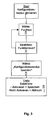
- ein Ablaufdiagramm einer Konfigurierung.
- Ein erfindungsgemäßes Lichtgitter 10 weist eine Lichtsendeleiste 12 auf, die eine Reihe nebeneinander angeordneter Lichtsender 14 aufweist und eine Lichtempfangsleiste 16, die den Lichtsendern 14 entsprechende, ebenfalls nebeneinander angeordnete Lichtempfänger 18 aufweist. Jeweils gegenüberliegende Lichtsender 14 und Lichtempfänger 18 bilden in bekannter Weise eine Vielzahl zueinander paralleler Lichtschranken 20, deren Lichtstrahl in Fig. 1 durch gestrichelte Linien dargestellt ist. Das Lichtgitter 10 mit seinen Lichtschranken 20 definiert somit zwischen Sendeleiste 12 und Empfangsleiste 16 einen Überwachungsbereich mit einem Schutzfeld 21. Das Lichtgitter 10 weist weiter wenigstens eine Steuer- und Auswerteeinheit auf. In dem dargestellten Ausführungsbeispiel ist sowohl in der Sende- 12 als auch in der Empfangsleiste 16 wenigstens je eine Steuer- und Auswerteeinheit 22 bzw. 24 vorgesehen. Die Steuer- und Auswerteeinheit 22 steuert die einzelnen Lichtsender 14 der Sendeleiste 12 und die Steuer- und Auswerteeinheit 24 der Empfangsleiste steuert die Lichtempfänger 18 und wertet deren Signale aus, so dass bei Unterbrechung einer oder mehrerer Lichtschranken 20 durch ein Objekt ein Warnsignal aus der Steuer- und Auswerteeinheit 24 ableitbar ist. Dieses Signal kann auch zum Abschalten einer gefährlichen Maschine dienen.
- Die grundsätzliche Funktionsweise eines solchen Lichtgitters ist z. B. in der DE 38 03 033 A1 beschrieben. Die einzelnen Lichtschranken 20 des Lichtgitters 10 werden zyklisch der Reihe nach aktiviert. Dabei werden die Lichtsender 14 und Lichtempfänger 18 auf optischem Wege über beispielsweise die erste und/oder letzte Lichtschranke synchronisiert, so dass immer der dem momentan sendenden Lichtsender gegenüberliegende Lichtempfänger aktiviert ist. Insbesondere ist dadurch eine elektrische Verbindung zwischen der Sendeleiste 12 und der Empfangsleiste 16 nicht notwendig.
- Das erfindungsgemäße Lichtgitter ist derart ausgebildet, dass unterschiedliche Konfigurationen je nach Einsatzzweck einstellbar sind. Die entsprechende Konfiguration muss in das Lichtgitter vor einem Ersteinsatz oder auch nach einem Austausch eingespeichert werden. Je nach dem welche Funktionen an dem Lichtgitter einstellbar sind, sind die Funktionsparameter in einem Konfigurationsmodus vor Inbetriebnahme eingebbar. Diese Funktionen können beispielsweise sein:
- eine Aktivierung oder Deaktivierung einer Schützkontrolle,
- eine Aktivierung oder Deaktivierung einer Wiederanlaufsperre,
- eine hohe oder niedrige Reichweite,
- welches Signal an einem Diagnoseausgang anliegen soll,
- welche einer vorgegebenen Auswahl von Muting-Zeiten eingestellt werden soll.
- Zur Eingabe der Konfigurationsparameter sind an dem Lichtgitter 10, vorzugsweise an der Steuer- und Auswerteeinheit 24 der Empfangsleiste 16, Konfigurationsmittel vorgesehen, die zwei Eingabeelemente, die als Taster 26 und 28 ausgebildet sind und ein Anzeigeelement, das als Sieben-Segment-Anzeige 30 ausgebildet ist, umfassen.
- Um die einzelnen Merkmale der Erfindung und die Funktionsweise zu verdeutlichen, wird im Folgenden beispielhaft der Ablauf einer Konfiguration für eine bestimmte Funktion beschrieben. Es soll beispielsweise die Reichweite des Lichtgitters konfiguriert werden. Dieser Ablauf ist auch in Fig. 3 dargestellt.
- Zunächst ist das Lichtgitter in den Konfigurationsmodus zu versetzen, also der Konfigurationsmodus zu aktivieren. Dazu werden beide Tasten 26 und 28 gleichzeitig für einen bestimmten Zeitraum gedrückt. Andere Aktivierungen sind möglich. So könnten z. B. beide Tasten zweimal hintereinander gleichzeitig gedrückt und wieder losgelassen werden.
- Nach Aktivierung des Konfigurationsmodus erscheint an der Sieben-Segment-Anzeige 30 ein Symbol, das diesen Zustand symbolisiert, z. B.

- Dann ist durch Drücken der Taste 26 die gewünschte Funktion, die eingestellt werden soll, zu wählen. Es ist zu bemerken, dass alle in dem Konfigurationsmodus einstellbaren Funktionen und deren Funktionswerte einen bestimmten "Wert" in der Sieben-Segment-Anzeige haben. Als Symbol für die Reichweite ist in diesem Ausführungsbeispiel das folgende gewählt.

- Die Taste 26 ist nun so oft zu drücken, bis das vorgenannte Symbol für die Reichweiteneinstellung erscheint. Dann ist über die zweite Taste 28 die Reichweite, also der gewünschte Funktionswert, zu selektieren. Wenn beispielsweise zwei verschiedenen Reichweiten "high" und "low" einstellbar sind und der höhere Reichweitenbereich eingestellt werden soll, ist die Taste 28 so oft zu drücken, bis z.B. das Symbolerscheint.

- Damit ist die Reichweite konfiguriert. Entweder kann nun durch Drücken der Taste 26 eine weitere, zu konfigurierende Funktion angewählt werden oder der Konfigurationsmodus beendet werden. Eine Beendigung geschieht dadurch, dass mit der ersten Taste 26 die Funktion "Konfiguration beenden", die beispielsweise angezeigt wird durch das Symbolgewählt wird und anschließend mit der zweiten Taste 28 selektiert wird, ob die eingegeben Konfiguration gespeichert und der Konfigurationsmodus verlassen werden soll oder ob die eingegeben Konfiguration nicht gespeichert und der Konfigurationsmodus verlassen werden soll. Dazu ist mit der zweiten Taste 28 zunächst zu selektieren, ob gespeichert werden soll oder nicht, was durch die Symbole
 und
und angezeigt wird,
Dann wird durch zweimaliges Betätigen des Tasters 28 die selektierte Funktion ausgeführt und der Konfigurationsmodus verlassen. - Ein besonderes Merkmal ist die Ausbildung der Steuer- und Auswerteeinheit, so dass eine fehlersichere Eingabe gewährleistet ist. Damit ist sichergestellt, dass beispielsweise ein dauerhaftes Drücken eines Tasters oder auch eine falsche Tastendruckfolge nicht dazu führt, dass eine nicht gewünschte Konfiguration eingestellt wird.
Claims (5)
- Sicherheits-Lichtgitter zur Überwachung eines Schutzfeldes mit einer Lichtsendeleiste (12), die eine Reihe nebeneinander angeordneter Lichtsender (14) aufweist und einer Lichtempfangsleiste (16), die den Lichtsendern (14) entsprechende ebenfalls nebeneinander angeordnete Lichtempfänger (18) aufweist, so dass eine Vielzahl zueinander paralleler und das Schutzfeld (21) bildender Lichtschranken (20) gebildet sind, mit wenigstens einer Steuer- und Auswerteeinheit (24), die die einzelnen Lichtschranken steuert und auswertet, so dass bei Unterbrechung einer oder mehrerer Lichtschranken (20) durch ein Objekt ein Warnsignal ableitbar ist und mit Konfigurationsmitteln zum Eingeben von Konfigurationsparametern zum Konfigurieren des Lichtgitters (10), dadurch gekennzeichnet,
dass die Konfigurationsmittel gebildet sind durch zwei Eingabeelemente (26 und 28) und wenigstens ein Anzeigeelement (30),
dass zum Aktivieren eines Konfigurationsmodus beide Eingabeelemente (26 und 28) gleichzeitig zu betätigen sind,
dass die Konfigurationsparameter umfassen- eine Aktivierung oder Deaktivierung einer Schützkontrolle,- eine Aktivierung oder Deaktivierung einer Wiederanlaufsperre,- eine hohe oder niedrige Reichweite,- Auswahl eines Signals zur Anlage an einen Diagnoseausgang- und/oder Auswahl einer von mehreren vorgegebenen Mutingzeitenund dass die Steuer- und Auswerteeinheit (24) derart ausgelegt ist, dass die Eingabe der Konfigurationsparameter über die Eingabeelemente (26, 28) fehlersicher erfolgt, wobei ein Festhalten eines Eingabeelementes oder eine falsche Folge von Eingabeelementbetätigungen durch die Steuer und Auswerteeinheit erkennbar ist und nicht zu einer Konfigurationsänderung führt. - Lichtgitter nach einem der vorhergehenden Ansprüche, dadurch gekennzeichnet, dass die zwei Eingabeelemente als Taster (26 und 28) ausgebildet sind.
- Lichtgitter nach einem der vorhergehenden Ansprüche, dadurch gekennzeichnet, dass das Anzeigeelement eine Sieben-Segment-Anzeige (30) ist.
- Lichtgitter nach einem der vorhergehenden Ansprüche, dadurch gekennzeichnet, dass die Konfigurationsmittel in die Lichtempfangsleiste (16) integriert sind.
- Lichtgitter nach einem der vorhergehenden Ansprüche, dadurch gekennzeichnet, dass eines der Eingabeelemente (26) zum Wählen einer Funktion und das andere zur Selektion eines Funktionswertes ausgelegt ist.
Applications Claiming Priority (2)
| Application Number | Priority Date | Filing Date | Title |
|---|---|---|---|
| DE20317976U | 2003-11-20 | ||
| DE20317976U DE20317976U1 (de) | 2003-11-20 | 2003-11-20 | Sicherheits-Lichtgitter |
Publications (2)
| Publication Number | Publication Date |
|---|---|
| EP1533630A1 EP1533630A1 (de) | 2005-05-25 |
| EP1533630B1 true EP1533630B1 (de) | 2006-09-20 |
Family
ID=31725268
Family Applications (1)
| Application Number | Title | Priority Date | Filing Date |
|---|---|---|---|
| EP04023321A Expired - Lifetime EP1533630B1 (de) | 2003-11-20 | 2004-09-30 | Sicherheits-Lichtgitter |
Country Status (4)
| Country | Link |
|---|---|
| US (1) | US7262403B2 (de) |
| EP (1) | EP1533630B1 (de) |
| AT (1) | ATE340366T1 (de) |
| DE (2) | DE20317976U1 (de) |
Families Citing this family (11)
| Publication number | Priority date | Publication date | Assignee | Title |
|---|---|---|---|---|
| DE102005003254B4 (de) * | 2005-01-24 | 2007-10-04 | Sick Ag | Optoelektronischer Sensor und Konfigurationsverfahren |
| JP2007223171A (ja) * | 2006-02-23 | 2007-09-06 | Mitsubishi Heavy Ind Ltd | 印刷機および印刷機の排紙装置 |
| DE102007044680B4 (de) | 2007-09-19 | 2013-01-03 | Sick Ag | Sicherheits-Lichtgitter |
| DE102007044679B3 (de) * | 2007-09-19 | 2008-11-27 | Sick Ag | Konfigurationsmittel für Sicherheits-Lichtgitter |
| US7810697B2 (en) * | 2008-08-22 | 2010-10-12 | Honda Motor Co., Ltd. | Turntable welding system with light curtain protection |
| DE202009000776U1 (de) | 2009-01-21 | 2009-06-25 | Sick Ag | Sicherheits-Lichtgitter |
| FR2951264B1 (fr) | 2009-10-12 | 2014-04-11 | Schneider Electric Ind Sas | Dispositif de detection configurable |
| CN102059580A (zh) * | 2010-11-19 | 2011-05-18 | 上海中护电子有限公司 | 带ccd辅助检测的机床安全控制系统及其方法 |
| US8881629B2 (en) * | 2012-06-12 | 2014-11-11 | Graham Packaging Company, L.P. | Continuous motion de-flash trimming machine |
| DE102015113366B3 (de) * | 2015-08-13 | 2016-10-13 | Sick Ag | Lichtgitter und Verfahren zum Rücksetzen einer Konfiguration |
| IT201700109596A1 (it) | 2017-09-29 | 2019-03-29 | Omron Tateisi Electronics Co | Metodo per il funzionamento di una barriera di sicurezza e barriera di sicurezza. |
Family Cites Families (15)
| Publication number | Priority date | Publication date | Assignee | Title |
|---|---|---|---|---|
| DE2343096A1 (de) * | 1973-08-27 | 1975-03-13 | Wolfgang Beer | Sicherungsvorrichtung, insbesondere fuer werkzeugmaschinen, mit einer lichtschranke |
| JPS56114780A (en) * | 1980-02-16 | 1981-09-09 | Matsushita Electric Works Ltd | Detector for number of passing bodies |
| JPH0690900B2 (ja) * | 1988-11-14 | 1994-11-14 | 株式会社キーエンス | 多光軸光電スイッチ |
| DE3919167C1 (en) | 1989-06-12 | 1990-09-13 | Volker Von 6110 Dieburg De Kuczkowski | Security indicating device, e.g. for storage room - has sensors at opposite ends of passageways to determine presence of vehicle or person, and activates alarm and lamp upon object device |
| US5347117A (en) * | 1992-12-30 | 1994-09-13 | Allen-Bradley Company, Inc. | Operator interface for a photoelectric control unit |
| FR2757980B1 (fr) * | 1996-12-26 | 1999-03-05 | Sarl Scmd | Dispositif electrosensible de controle d'acces |
| DE19827692C2 (de) | 1998-06-22 | 2001-06-13 | Hoermann Kg Antriebstechnik | Codierschaltung sowie Verwendung derselben in einer Betätigungs- oder Steuereinrichtung für ein signalbetätigbares Schließsystem |
| EP1116963B1 (de) * | 2000-01-14 | 2013-03-06 | Keyence Corporation | Photoelektrischer Detektor |
| DE10046863C1 (de) | 2000-09-20 | 2002-01-10 | Leuze Lumiflex Gmbh & Co | Schnittstelle für Lichtschrankenanordnungen |
| DE10108962A1 (de) * | 2001-02-20 | 2002-09-12 | Pilz Gmbh & Co | Verfahren und Vorrichtung zum Programmieren einer Sicherheitssteuerung |
| JP2003218679A (ja) * | 2002-01-25 | 2003-07-31 | Keyence Corp | 多光軸光電式安全装置 |
| JP3854512B2 (ja) * | 2002-01-25 | 2006-12-06 | 株式会社キーエンス | 多光軸光電式安全装置用の表示モニタ |
| DE10216123B4 (de) | 2002-04-12 | 2008-04-10 | Sick Ag | Überwachungsvorrichtung |
| DE10216122A1 (de) * | 2002-04-12 | 2003-10-30 | Sick Ag | Objekterfassung |
| DE10233258B4 (de) * | 2002-07-23 | 2006-07-13 | Leuze Lumiflex Gmbh + Co. Kg | Lichtgitter |
-
2003
- 2003-11-20 DE DE20317976U patent/DE20317976U1/de not_active Expired - Lifetime
-
2004
- 2004-09-30 EP EP04023321A patent/EP1533630B1/de not_active Expired - Lifetime
- 2004-09-30 AT AT04023321T patent/ATE340366T1/de not_active IP Right Cessation
- 2004-09-30 DE DE502004001527T patent/DE502004001527D1/de not_active Expired - Lifetime
- 2004-11-10 US US10/985,294 patent/US7262403B2/en not_active Expired - Fee Related
Also Published As
| Publication number | Publication date |
|---|---|
| DE502004001527D1 (de) | 2006-11-02 |
| EP1533630A1 (de) | 2005-05-25 |
| DE20317976U1 (de) | 2004-02-12 |
| ATE340366T1 (de) | 2006-10-15 |
| US20050109920A1 (en) | 2005-05-26 |
| US7262403B2 (en) | 2007-08-28 |
Similar Documents
| Publication | Publication Date | Title |
|---|---|---|
| EP1933174B1 (de) | Lichtgitter | |
| EP1533630B1 (de) | Sicherheits-Lichtgitter | |
| DE60305751T2 (de) | Anzeigemonitor für photoelektrische optische Mehrwegsicherheitsvorrichtung und einen Anzeigemonitor aufweisende, photoelektrische, optische Mehrwegsicherheitsvorrichtung | |
| EP1657819B1 (de) | Kochfeldsteuerung | |
| EP1946154B1 (de) | Verfahren und bedieneinheit zum konfigurieren und überwachen einer einrichtung mit funktionaler sicherheit | |
| EP2071363B1 (de) | Lichtgitter und Verfahren zu dessen Betrieb | |
| EP1835310A2 (de) | Lichtgitter | |
| DE102009021706A1 (de) | Bereichsbüberwachungssensor | |
| EP1353196A1 (de) | Objekterfassung und Lichtgitter | |
| DE102007044680B4 (de) | Sicherheits-Lichtgitter | |
| EP1443343B1 (de) | Optischer Sensor mit mehreren Schaltausgängen | |
| DE60307914T2 (de) | Photoelektrische, optische Mehrwegsicherheitsvorrichtung | |
| EP2492714A1 (de) | Verfahren zum Betreiben eines Sicherheitslichtgitters und Sicherheitslichtgitter | |
| EP1437542B1 (de) | Lichtgitter und Verfahren zu dessen Justierung | |
| WO2014206886A1 (de) | Verfahren zur synchronisation eines lichtgitters | |
| EP1921386A2 (de) | Kochfeldsteuerung und Verfahren zum manuellen Einstellen an einer Bedienlinie | |
| DE102007044679B3 (de) | Konfigurationsmittel für Sicherheits-Lichtgitter | |
| EP3594553A1 (de) | Vorrichtung zur überwachung eines gefahrenbereichs | |
| DE102016107583A1 (de) | Bedienpanel zum Steuern einer industriellen Anlage | |
| DE202009000776U1 (de) | Sicherheits-Lichtgitter | |
| EP1391752B1 (de) | Lichtgitter | |
| DE102017119275A1 (de) | Lichtvorhang | |
| DE102009031226B4 (de) | Sicherheitslichtgitter | |
| EP1772753B1 (de) | Verfahren zum Betrieb eines Lichtgitters | |
| DE10359561A1 (de) | Bedienelement für ein Haushaltsgerät |
Legal Events
| Date | Code | Title | Description |
|---|---|---|---|
| PUAI | Public reference made under article 153(3) epc to a published international application that has entered the european phase |
Free format text: ORIGINAL CODE: 0009012 |
|
| AK | Designated contracting states |
Kind code of ref document: A1 Designated state(s): AT BE BG CH CY CZ DE DK EE ES FI FR GB GR HU IE IT LI LU MC NL PL PT RO SE SI SK TR |
|
| AX | Request for extension of the european patent |
Extension state: AL HR LT LV MK |
|
| 17P | Request for examination filed |
Effective date: 20051012 |
|
| AKX | Designation fees paid |
Designated state(s): AT BE BG CH CY CZ DE DK EE ES FI FR GB GR HU IE IT LI LU MC NL PL PT RO SE SI SK TR |
|
| GRAP | Despatch of communication of intention to grant a patent |
Free format text: ORIGINAL CODE: EPIDOSNIGR1 |
|
| GRAS | Grant fee paid |
Free format text: ORIGINAL CODE: EPIDOSNIGR3 |
|
| GRAA | (expected) grant |
Free format text: ORIGINAL CODE: 0009210 |
|
| AK | Designated contracting states |
Kind code of ref document: B1 Designated state(s): AT BE BG CH CY CZ DE DK EE ES FI FR GB GR HU IE IT LI LU MC NL PL PT RO SE SI SK TR |
|
| PG25 | Lapsed in a contracting state [announced via postgrant information from national office to epo] |
Ref country code: RO Free format text: LAPSE BECAUSE OF FAILURE TO SUBMIT A TRANSLATION OF THE DESCRIPTION OR TO PAY THE FEE WITHIN THE PRESCRIBED TIME-LIMIT Effective date: 20060920 Ref country code: NL Free format text: LAPSE BECAUSE OF FAILURE TO SUBMIT A TRANSLATION OF THE DESCRIPTION OR TO PAY THE FEE WITHIN THE PRESCRIBED TIME-LIMIT Effective date: 20060920 Ref country code: IE Free format text: LAPSE BECAUSE OF FAILURE TO SUBMIT A TRANSLATION OF THE DESCRIPTION OR TO PAY THE FEE WITHIN THE PRESCRIBED TIME-LIMIT Effective date: 20060920 Ref country code: FI Free format text: LAPSE BECAUSE OF FAILURE TO SUBMIT A TRANSLATION OF THE DESCRIPTION OR TO PAY THE FEE WITHIN THE PRESCRIBED TIME-LIMIT Effective date: 20060920 Ref country code: SK Free format text: LAPSE BECAUSE OF FAILURE TO SUBMIT A TRANSLATION OF THE DESCRIPTION OR TO PAY THE FEE WITHIN THE PRESCRIBED TIME-LIMIT Effective date: 20060920 Ref country code: SI Free format text: LAPSE BECAUSE OF FAILURE TO SUBMIT A TRANSLATION OF THE DESCRIPTION OR TO PAY THE FEE WITHIN THE PRESCRIBED TIME-LIMIT Effective date: 20060920 Ref country code: CZ Free format text: LAPSE BECAUSE OF FAILURE TO SUBMIT A TRANSLATION OF THE DESCRIPTION OR TO PAY THE FEE WITHIN THE PRESCRIBED TIME-LIMIT Effective date: 20060920 Ref country code: PL Free format text: LAPSE BECAUSE OF FAILURE TO SUBMIT A TRANSLATION OF THE DESCRIPTION OR TO PAY THE FEE WITHIN THE PRESCRIBED TIME-LIMIT Effective date: 20060920 |
|
| REG | Reference to a national code |
Ref country code: GB Ref legal event code: FG4D Free format text: NOT ENGLISH |
|
| PG25 | Lapsed in a contracting state [announced via postgrant information from national office to epo] |
Ref country code: BE Free format text: LAPSE BECAUSE OF NON-PAYMENT OF DUE FEES Effective date: 20060930 Ref country code: MC Free format text: LAPSE BECAUSE OF NON-PAYMENT OF DUE FEES Effective date: 20060930 |
|
| GBT | Gb: translation of ep patent filed (gb section 77(6)(a)/1977) |
Effective date: 20060920 |
|
| REG | Reference to a national code |
Ref country code: CH Ref legal event code: EP |
|
| REG | Reference to a national code |
Ref country code: IE Ref legal event code: FG4D Free format text: LANGUAGE OF EP DOCUMENT: GERMAN |
|
| REF | Corresponds to: |
Ref document number: 502004001527 Country of ref document: DE Date of ref document: 20061102 Kind code of ref document: P |
|
| PG25 | Lapsed in a contracting state [announced via postgrant information from national office to epo] |
Ref country code: DK Free format text: LAPSE BECAUSE OF FAILURE TO SUBMIT A TRANSLATION OF THE DESCRIPTION OR TO PAY THE FEE WITHIN THE PRESCRIBED TIME-LIMIT Effective date: 20061220 Ref country code: BG Free format text: LAPSE BECAUSE OF FAILURE TO SUBMIT A TRANSLATION OF THE DESCRIPTION OR TO PAY THE FEE WITHIN THE PRESCRIBED TIME-LIMIT Effective date: 20061220 Ref country code: SE Free format text: LAPSE BECAUSE OF FAILURE TO SUBMIT A TRANSLATION OF THE DESCRIPTION OR TO PAY THE FEE WITHIN THE PRESCRIBED TIME-LIMIT Effective date: 20061220 |
|
| PG25 | Lapsed in a contracting state [announced via postgrant information from national office to epo] |
Ref country code: ES Free format text: LAPSE BECAUSE OF FAILURE TO SUBMIT A TRANSLATION OF THE DESCRIPTION OR TO PAY THE FEE WITHIN THE PRESCRIBED TIME-LIMIT Effective date: 20061231 |
|
| RAP2 | Party data changed (patent owner data changed or rights of a patent transferred) |
Owner name: SICK AG |
|
| ET | Fr: translation filed | ||
| NLV1 | Nl: lapsed or annulled due to failure to fulfill the requirements of art. 29p and 29m of the patents act | ||
| PG25 | Lapsed in a contracting state [announced via postgrant information from national office to epo] |
Ref country code: PT Free format text: LAPSE BECAUSE OF FAILURE TO SUBMIT A TRANSLATION OF THE DESCRIPTION OR TO PAY THE FEE WITHIN THE PRESCRIBED TIME-LIMIT Effective date: 20070312 |
|
| REG | Reference to a national code |
Ref country code: IE Ref legal event code: FD4D |
|
| PLBE | No opposition filed within time limit |
Free format text: ORIGINAL CODE: 0009261 |
|
| STAA | Information on the status of an ep patent application or granted ep patent |
Free format text: STATUS: NO OPPOSITION FILED WITHIN TIME LIMIT |
|
| 26N | No opposition filed |
Effective date: 20070621 |
|
| PG25 | Lapsed in a contracting state [announced via postgrant information from national office to epo] |
Ref country code: AT Free format text: LAPSE BECAUSE OF NON-PAYMENT OF DUE FEES Effective date: 20060930 |
|
| BERE | Be: lapsed |
Owner name: SICK A.G. Effective date: 20060930 |
|
| PG25 | Lapsed in a contracting state [announced via postgrant information from national office to epo] |
Ref country code: GR Free format text: LAPSE BECAUSE OF FAILURE TO SUBMIT A TRANSLATION OF THE DESCRIPTION OR TO PAY THE FEE WITHIN THE PRESCRIBED TIME-LIMIT Effective date: 20061221 |
|
| PG25 | Lapsed in a contracting state [announced via postgrant information from national office to epo] |
Ref country code: EE Free format text: LAPSE BECAUSE OF FAILURE TO SUBMIT A TRANSLATION OF THE DESCRIPTION OR TO PAY THE FEE WITHIN THE PRESCRIBED TIME-LIMIT Effective date: 20060920 |
|
| PG25 | Lapsed in a contracting state [announced via postgrant information from national office to epo] |
Ref country code: TR Free format text: LAPSE BECAUSE OF FAILURE TO SUBMIT A TRANSLATION OF THE DESCRIPTION OR TO PAY THE FEE WITHIN THE PRESCRIBED TIME-LIMIT Effective date: 20060920 Ref country code: LU Free format text: LAPSE BECAUSE OF NON-PAYMENT OF DUE FEES Effective date: 20060930 Ref country code: HU Free format text: LAPSE BECAUSE OF FAILURE TO SUBMIT A TRANSLATION OF THE DESCRIPTION OR TO PAY THE FEE WITHIN THE PRESCRIBED TIME-LIMIT Effective date: 20070321 |
|
| PG25 | Lapsed in a contracting state [announced via postgrant information from national office to epo] |
Ref country code: CY Free format text: LAPSE BECAUSE OF FAILURE TO SUBMIT A TRANSLATION OF THE DESCRIPTION OR TO PAY THE FEE WITHIN THE PRESCRIBED TIME-LIMIT Effective date: 20060920 |
|
| REG | Reference to a national code |
Ref country code: CH Ref legal event code: PL |
|
| PG25 | Lapsed in a contracting state [announced via postgrant information from national office to epo] |
Ref country code: LI Free format text: LAPSE BECAUSE OF NON-PAYMENT OF DUE FEES Effective date: 20060930 Ref country code: CH Free format text: LAPSE BECAUSE OF NON-PAYMENT OF DUE FEES Effective date: 20060930 |
|
| PG25 | Lapsed in a contracting state [announced via postgrant information from national office to epo] |
Ref country code: LI Free format text: LAPSE BECAUSE OF NON-PAYMENT OF DUE FEES Effective date: 20080930 Ref country code: CH Free format text: LAPSE BECAUSE OF NON-PAYMENT OF DUE FEES Effective date: 20080930 |
|
| PGFP | Annual fee paid to national office [announced via postgrant information from national office to epo] |
Ref country code: GB Payment date: 20130920 Year of fee payment: 10 |
|
| GBPC | Gb: european patent ceased through non-payment of renewal fee |
Effective date: 20140930 |
|
| PG25 | Lapsed in a contracting state [announced via postgrant information from national office to epo] |
Ref country code: GB Free format text: LAPSE BECAUSE OF NON-PAYMENT OF DUE FEES Effective date: 20140930 |
|
| REG | Reference to a national code |
Ref country code: FR Ref legal event code: PLFP Year of fee payment: 12 |
|
| PGFP | Annual fee paid to national office [announced via postgrant information from national office to epo] |
Ref country code: FR Payment date: 20150923 Year of fee payment: 12 |
|
| REG | Reference to a national code |
Ref country code: FR Ref legal event code: ST Effective date: 20170531 |
|
| PG25 | Lapsed in a contracting state [announced via postgrant information from national office to epo] |
Ref country code: FR Free format text: LAPSE BECAUSE OF NON-PAYMENT OF DUE FEES Effective date: 20160930 |
|
| PGFP | Annual fee paid to national office [announced via postgrant information from national office to epo] |
Ref country code: IT Payment date: 20170926 Year of fee payment: 14 Ref country code: DE Payment date: 20170921 Year of fee payment: 14 |
|
| REG | Reference to a national code |
Ref country code: DE Ref legal event code: R119 Ref document number: 502004001527 Country of ref document: DE |
|
| PG25 | Lapsed in a contracting state [announced via postgrant information from national office to epo] |
Ref country code: IT Free format text: LAPSE BECAUSE OF NON-PAYMENT OF DUE FEES Effective date: 20180930 Ref country code: DE Free format text: LAPSE BECAUSE OF NON-PAYMENT OF DUE FEES Effective date: 20190402 |