EP1533576A2 - Dispositif de conditionnement d'air avec une meilleure perception d'utilisateur - Google Patents
Dispositif de conditionnement d'air avec une meilleure perception d'utilisateur Download PDFInfo
- Publication number
- EP1533576A2 EP1533576A2 EP20040255802 EP04255802A EP1533576A2 EP 1533576 A2 EP1533576 A2 EP 1533576A2 EP 20040255802 EP20040255802 EP 20040255802 EP 04255802 A EP04255802 A EP 04255802A EP 1533576 A2 EP1533576 A2 EP 1533576A2
- Authority
- EP
- European Patent Office
- Prior art keywords
- air conditioner
- character
- character image
- operational state
- user
- Prior art date
- Legal status (The legal status is an assumption and is not a legal conclusion. Google has not performed a legal analysis and makes no representation as to the accuracy of the status listed.)
- Granted
Links
Images


Classifications
-
- F—MECHANICAL ENGINEERING; LIGHTING; HEATING; WEAPONS; BLASTING
- F24—HEATING; RANGES; VENTILATING
- F24F—AIR-CONDITIONING; AIR-HUMIDIFICATION; VENTILATION; USE OF AIR CURRENTS FOR SCREENING
- F24F1/00—Room units for air-conditioning, e.g. separate or self-contained units or units receiving primary air from a central station
-
- F—MECHANICAL ENGINEERING; LIGHTING; HEATING; WEAPONS; BLASTING
- F24—HEATING; RANGES; VENTILATING
- F24F—AIR-CONDITIONING; AIR-HUMIDIFICATION; VENTILATION; USE OF AIR CURRENTS FOR SCREENING
- F24F11/00—Control or safety arrangements
- F24F11/30—Control or safety arrangements for purposes related to the operation of the system, e.g. for safety or monitoring
-
- F—MECHANICAL ENGINEERING; LIGHTING; HEATING; WEAPONS; BLASTING
- F24—HEATING; RANGES; VENTILATING
- F24F—AIR-CONDITIONING; AIR-HUMIDIFICATION; VENTILATION; USE OF AIR CURRENTS FOR SCREENING
- F24F1/00—Room units for air-conditioning, e.g. separate or self-contained units or units receiving primary air from a central station
- F24F1/0007—Indoor units, e.g. fan coil units
- F24F1/0043—Indoor units, e.g. fan coil units characterised by mounting arrangements
- F24F1/005—Indoor units, e.g. fan coil units characterised by mounting arrangements mounted on the floor; standing on the floor
-
- F—MECHANICAL ENGINEERING; LIGHTING; HEATING; WEAPONS; BLASTING
- F24—HEATING; RANGES; VENTILATING
- F24F—AIR-CONDITIONING; AIR-HUMIDIFICATION; VENTILATION; USE OF AIR CURRENTS FOR SCREENING
- F24F1/00—Room units for air-conditioning, e.g. separate or self-contained units or units receiving primary air from a central station
- F24F1/0007—Indoor units, e.g. fan coil units
- F24F1/0059—Indoor units, e.g. fan coil units characterised by heat exchangers
- F24F1/0063—Indoor units, e.g. fan coil units characterised by heat exchangers by the mounting or arrangement of the heat exchangers
-
- F—MECHANICAL ENGINEERING; LIGHTING; HEATING; WEAPONS; BLASTING
- F24—HEATING; RANGES; VENTILATING
- F24F—AIR-CONDITIONING; AIR-HUMIDIFICATION; VENTILATION; USE OF AIR CURRENTS FOR SCREENING
- F24F1/00—Room units for air-conditioning, e.g. separate or self-contained units or units receiving primary air from a central station
- F24F1/0007—Indoor units, e.g. fan coil units
- F24F1/0071—Indoor units, e.g. fan coil units with means for purifying supplied air
- F24F1/0073—Indoor units, e.g. fan coil units with means for purifying supplied air characterised by the mounting or arrangement of filters
-
- F—MECHANICAL ENGINEERING; LIGHTING; HEATING; WEAPONS; BLASTING
- F24—HEATING; RANGES; VENTILATING
- F24F—AIR-CONDITIONING; AIR-HUMIDIFICATION; VENTILATION; USE OF AIR CURRENTS FOR SCREENING
- F24F11/00—Control or safety arrangements
- F24F11/50—Control or safety arrangements characterised by user interfaces or communication
- F24F11/52—Indication arrangements, e.g. displays
Definitions
- the present invention relates to home appliances such as air conditioners, and more particularly, to a home appliance capable of enhancing a user's perception.
- the air conditioner includes a display window at one side, so that an image adapted for the air conditioner or a character image having a user's high preference is displayed on the display window.
- a manipulation operation of the air conditioner is more convenient through a change of the character image.
- the air conditioner can suitably display the character image depending on an operational state, thereby enhancing a user's perception.
- An air conditioner that is generally used at home includes a manipulation part such as a control panel, a display window on which an operational state of the air conditioner is displayed, and a driver part having a plurality of equipments suitable for a characteristic of the air conditioner.
- the display window is configured to simply display the operational state of the air conditioner with digits, arrows, shades, display of liquid crystal display (LCD), and so on. Because the display window which allows a user to observe the operational state of the air conditioner, is constructed too simply, the user cannot observe the operational state of the air conditioner at a glance. In other words, the user must look at digits, arrows, and other characters.
- the air conditioner is installed in an indoor space or wall of an office or house so as to heat or cool its interior.
- the air conditioner includes a compressor, a condenser, an expansion value and an evaporator and performs a series of a refrigeration cycle.
- the air conditioner has a plurality of operational states, such as a dehumidifying state, a cooling state, and a rapid cooling state.
- the user must approach the indoor unit of the air conditioner so as to identify the operational state of the air conditioner. Even if a display window is installed in an indoor unit, the user must look at an arrow or appellation of the operational state near the indoor unit.
- the complex operational state of the air conditioner can be perceived through digits, letters, arrows, symbols, and so on.
- the conventional air conditioner has drawbacks in that freshness and animation are lack because temperature, humidity and operational states are displayed in a static manner.
- an air conditioner having an enhanced user perception, in which a character image displayed on a display window is changed depending on an operational state of the air conditioner, so that a user can perceive the operational state more conveniently.
- the operational state of the air conditioner can be presented using a voice or other audible signal.
- an air conditioner having an enhanced user perception, in which a display window disposed at a front side of the air conditioner can be stably fixed to increase a readability of the display window.
- an air conditioner which includes: an external panel; and a display part formed on the external panel, for displaying a specific character and/or a character image of the character.
- a home appliance comprising: an external panel; and a display part formed on the external panel, for displaying a specific character and/or a character image of the character.
- an air conditioner having an enhanced user perception includes: an input part for manipulation by a user to control an operation of the air conditioner; an operational state display part for displaying a predetermined character and/or a character image of the character at least adapted for an operational state of the air conditioner; and a control part for judging a signal transmitted from the input part to control the air conditioner and judging the character and/or the character image adapted for the operational state of the air conditioner to transmit a predetermined character and/or a character image to the operational state display part and allow the transmitted character and/or the character image to be displayed on the operational state display part.
- a user's own character image can be displayed on an air conditioner, so that the will to purchase the product and a user's satisfaction are increased.
- a character can be changed depending on a user's preference, thereby satisfying the user greater.
- the character can be changed conveniently, a user's convenience is improved.
- an action of a character displayed on an air conditioner can be visibly changed in various shapes, depending on characteristics of operational states of the air conditioner. Therefore, the operational state of the air conditioner can be easily perceived. Due to a voice output part, the operational state can be perceived more reliably. Further, a user can be greatly satisfied by recording his or her favorite person's voice for the voice output.
- a display window of an air conditioner can be mounted reliably and stably, a process required for mounting the display window is simplified and the number of necessary parts is reduced. The user can correctly check a displayed state of the display window without regard to a use state of the air conditioner.
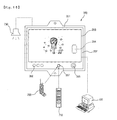
- Fig. 1 is a view illustrating a use state of an air conditioner according to the present invention.
- an air conditioner according to the present invention includes a first indoor unit installed in an interior of a building, a second indoor unit 200 installed in a different space spaced apart from the first indoor unit 100, an outdoor unit 10 communicating with the indoor units 100 and 200 through a refrigerant pipe 12, and a data input part 20 for controlling display windows of the indoor units 100 and 200.
- the data input part 20 is connected with the indoor units 100 and 200 through a cable 104.
- the outdoor unit 10 includes an outdoor fan 11 for performing a heat exchange with respect to a refrigerant.
- the data input part 20 may be a computer that is widely used at home. At least one of the cable 104, a network and a wireless communication network can be applied to the computer 20.
- the indoor units 100 and 200 include display parts 160 and 350 on which at least character image is displayed.
- a variety of character images can be applied depending on kinds of the air conditioner. For example, a penguin image can be applied to an air conditioner and a duck image can be applied to a cooker.
- the character images may be previously stored in a storage medium provided inside the air conditioner, or may be directly inputted through the data input part 20 by a user. The character image is so large that the user can look the character image from a long distance and perceive the shape of the character image.
- the character may be an animal-shaped image. Except for the animal-shaped image, a mascot-like image whose meaning is perceivable may be used.
- each of the display parts 160 and 350 can further include a state display window for accurately display an operational state of the air conditioner with a numerical value or arrow, as well as the character image.
- the present invention can also be applied when one indoor unit is used. This is also included within the spirit and scope of the present invention.
- the first indoor unit 100 is a floor standing type indoor unit and the second indoor unit 200 is a wall mount type indoor unit. Since a plurality of indoor units are installed in separated indoor spaces, the heating/cooling can be perfectly achieved with regard to a overall indoor area.
- Predetermined character images are displayed on the display parts 160 and 350 of the air conditioner.
- the character images may be an image that is previously stored in a storage medium provided inside the air conditioner, or an image that is arbitrarily inputted through the data input part by the user.
- the character images displayed on the display parts 160 and 350 may be an equal character but different image representing a corresponding operational state, depending on the operational states of the air conditioner.
- the character images may also be a still picture.
- the user can conveniently perceive the operational state of the air conditioner, and the convenience in use of the air conditioner and the product image can be improved much more.
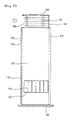
- Fig. 2 is a side view of the first indoor unit 100 according to the present invention.
- the first indoor unit 100 includes a front panel 110 elongated up and down to form a front appearance, a side panel 120 forming a side appearance, a rear panel 130 forming a rear appearance, an upper panel 140 forming an upper appearance, and a base pan 150 forming a bottom surface.
- the display part 160 is disposed at an upper center of the front panel 110.
- a set character image is displayed on the display part 160.
- the display part 160 includes a liquid crystal display(LCD) and/or a light emitting device (LED).
- the character image may be an AVATA or any other images.
- the LCD is a display device to which an operation of liquid crystal (LC) is applied.
- the liquid crystal will now be described in detail.
- Liquid crystal molecule is an intermediary substance between a liquid state and a solid state.
- the liquid crystal molecule is called an an-isotropic liquid, because the molecular arrangement is regular in a certain direction, while the molecular arrangement is irregular in a different direction and the liquid crystal is optically in a crystal state.
- the liquid crystal that is an organic molecule having liquidity like a liquid is regularly arranged like a crystal.
- the LCD displays an image using a property that the molecular arrangement is changed due to an external electric field.
- the LCD has characteristics of slimness, light weight and low power consumption regardless of a screen size.
- the LCD can be conveniently installed in the air conditioner having a narrow space. Also, the LCD can reproduce full colors using red, green and blue colors. Therefore, a colorful character image can be implemented without troubles. Since an operation principle of the LCD and a color reproducing method of a back light have been well known, their detailed descriptions will be omitted. Further, since the LED reproduces the red, green and blue colors through a light emitting semiconductor device, it can act as a display device and may be adapted for a large screen. Since the LCD can reproduce various colors, a user's aesthetic sense and preference to the product are enhanced much more.
- the character image can be displayed in various shapes, and various AVATAs can be displayed depending on the operational states of the air conditioner.
- the AVATA is used to exhibit the otherself of a specific individual on the virtual space.
- a specific character is disposed in various poses, locations, backgrounds and features without any change in the subject of the character. Therefore, it is useful to show various features to the user. For example, when the air conditioner is turned on, the character appears and greets with a bright smile. While the air conditioner is operating, the character acts variously depending on the operation modes. In other words, in a "cooling operation", the character plays ball with a penguin, and in a "dehumidifying operation", the character squeezes water from the clothes. Further, the character is different depending on a current temperature. For example, if the current temperature is higher than a desired temperature, the character perspires profusely, and if the current temperature is lower than the desired temperature, the character shrinks with cold. At this time, it is preferable to use the same character.
- the first indoor unit 100 is configured to inform the current operational state and temperature of the air conditioner with voice, in addition to the character image.
- the current state and operational state of the air conditioner are informed through a speaker in a human voice under a control of a controller (not shown), for example, "This air conditioner is now in the cooling operation", "A current temperature is 26 degrees", or "A current air flow is strong".
- the information can be expressed corresponding to the shape of AVATA or separately without association with it.
- a storage medium and/or microphone for a recording function are/is provided inside the first indoor unit 100.
- the user can record his or her own voice or replace the set voice with a separately recorded sound. Therefore, the operational state of the air conditioner is informed with the user's own voice or a separate melody.
- the voice can be stored through the data input part 20.
- the LCD of the display part 160 is set to a power saving mode in operation. If the operation of the air conditioner is stopped, the AVATA displayed on the display part 160 greets and disappears.
- a receiving unit is further provided inside the first indoor unit 100 so as to download the AVATA through a direct connection or wireless connection with an external unit.
- the AVATA can be downloaded via the Internet, a line telephone and a cellular phone.
- the data input part 20 is connected to the indoor units 100 and 200.
- the data input part 20 is connected to the indoor units 100 and 200 through the cable 104, and more particularly, to the controller for controlling the display part 160.
- the user can directly create or program desired character on the computer 20 and upload it to the controller.
- the user can download it through the communication networks, such as the Internet or the telephone.
- the user can access the Internet through the computer 20, download the character provided from a corresponding website, and upload it to the controller.
- the user can download the character through a mobile equipment such as a cellular phone and transmit it to the controllers of the indoor units 100 and 200.
- a state display part 170 is further provided in a lower portion of the display part 160.
- the state display part 170 displays the operational state of the air conditioner with diagrams, letters and numerical values.
- the state display part 170 can be configured with an LCD or LED.
- a plurality of manipulation buttons 180 are provided on both sides of the display part 160. The operation of the air conditioner can be set using the manipulation buttons 180. Further, the manipulation buttons are used to set or modify the display part 160.
- the air conditioner can be operated by a remote controller.
- Fig. 3 is a partial enlarged view of the front panel of the air conditioner according to the present invention. A construction of the display part 160 will be fully understood with reference to Fig. 3.
- An inlet port 122 is formed at the side panel 120 providing a side appearance of the first indoor unit 100.
- An air is introduced from an indoor space through the inlet port 122.
- An inlet grill 124 is further installed in an outer side of the inlet port 122.
- An air filter (not shown) for filtering foreign substance contained in the introduced air is further provided in an inner side of the inlet grill 124.
- the upper panel 140 moves up and down.
- the upper panel 140 is supported by a supporter 142, which is provided in right and left sides and front and rear sides, and moves upwards.
- a rear blocking plate 144 slides from an upper end of the first indoor unit 100 and is protruded upwards.
- a plurality of outlet ribs 146 are formed in right and left sides of the supporter 142.
- the outlet ribs 146 are formed up and down spaced apart from each other by a predetermined interval.
- the outlet ribs 146 guide a discharge direction, so that the air discharged from the inside of the first indoor unit 100 upwards can be discharged in a front or side direction.
- a heat exchanger (not shown) is installed inside the first indoor unit 100, allowing a heat exchange between the air introduced through the inlet port 122 and the refrigerant flowing through the first indoor unit 100.
- a blowing fan (not shown) and a motor (not shown) are embedded. The blowing fan forcibly blows the air so as to again discharge the air, which is introduced through the inlet port 122, to the indoor space through the upper end of the first indoor unit 100.
- the motor produces a rotational power to the blowing fan.
- the outdoor unit 10 performs a refrigeration cycle of the air conditioner together with the indoor units 100 and 200.
- a plurality of parts such as a compressor for compressing the refrigerant and an outdoor heat exchanger for performing a heat exchange, are embedded in the inside of the outdoor unit 10.
- Figs. 4 and 5 are a front view and a side view illustrating an operation of the air conditioner according to the present invention, respectively.
- the air conditioner is driven using the remote controller or by pressing the manipulation button 180. If the air conditioner begins to operate, the air of the indoor space is introduced into the first indoor unit 100 through the inlet port 122.
- the air filter (not shown) filters foreign substance from the introduced air.
- the heat exchanger (not shown) provided inside the first indoor unit 100 performs a heat exchanger between the air and the refrigerant, thereby reducing the temperature. At this time, the heat exchanger provided inside the first indoor unit 100 acts as the evaporator. Therefore, the air introduced from the indoor space is deprived of heat by the refrigerant flowing through the heat exchanger, thereby reducing the temperature.
- the cooled air is introduced into the blowing fan (not shown).
- the blowing fan (not shown) forcibly blows the air upwards and discharges it into the indoor space.
- the air conditioner when the air conditioner operates, the upper panel 140 moves upwards. Accordingly, the outlet rib 146 provided in the supporter 142 is exposed externally.
- the rear blocking plate 144 is integrally formed at the rear end of the upper panel 140. The rear blocking plate 144 slides upwards together with the upper panel 140 and is exposed. Therefore, the air discharged upwards is not discharged in a rear direction but discharged a front or side direction. At this time, the air is discharged toward the indoor space in such a state that the discharge direction is adjusted by the outlet rib 146. As a result, the air discharged into the indoor space is a cooled air, whose heat is exchanged by the heat exchanger. Therefore, a cool air is supplied to the indoor space and thus a cooling operation is achieved.
- a heat exchange is also performed in the outdoor unit 10.
- the heat exchanger of the first indoor unit 100 acts as the evaporator
- the heat exchanger of the outdoor unit 10 acts as the condenser. Accordingly, the temperature of the external air introduced into the outdoor unit 10 is increased and then discharged into the outside. In this manner, the cooling operation is performed in the first indoor unit 100 and the heating operation is performed. As a whole, one refrigeration cycle is achieved.
- the display part 160 is also turned on so that various AVATAs appear and inform the operational states of the air conditioner. For example, when the air conditioner is initially turned on, the set AVATA appears and greets with a bright smile. In the cooling mode, an image that the AVATA plays ball with a penguin in the South Pole can be displayed. Of course, if the user sets other character, other shape can be displayed. If the cooling operation is still necessary because the current temperature does not reach the set temperature, an image that the AVATA perspires profusely can be displayed.
- the operational state can be informed in the voice, except that the character is displayed on the display part 160. For example, when the air conditioner operates in the cooling mode, a message of "this air conditioner is now in the cooling operation" is outputted through the speaker 190. If the user inputs a recorded voice or melody, a corresponding message may be outputted.
- the heat exchanger embedded in the first indoor unit 100 acts as the condenser, so that the temperature of the introduced indoor air rises.
- the display part 160 is also turned on to display the greeting AVATA. If the user selects the heating mode, the set image of the AVATA is displayed. For example, an image that the AVATA bathes in the sea can be displayed. Also, various images can be displayed depending on the programs set by the user.
- the AVATA greets cutely and disappears. In this manner, the heating operation of the air conditioner can be ended.
- the program can be downloaded using the communication equipment, such as the Internet or cellular phone, or can directly input it.
- Figs. 6 to 15 are views illustrating the construction and operation of the second indoor unit in the air conditioner according to the present invention.
- the second indoor unit is the wall mount type and has a small size, so that an installation space for the display part is small and an air discharge space is narrow. Therefore, an additional structure for mounting the display part is required.
- the second indoor unit must be formed in a specific structure, which can meet such requirements.
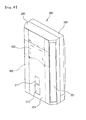
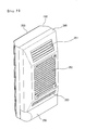
- Figs. 6 and 7 are a front perspective view and a rear perspective view of the second indoor unit according to the present invention, respectively.
- the second indoor unit 200 includes: a front panel 201 forming a front surface of the second indoor unit 200; a front frame 280 into which the front panel 201 is fitted to thereby form a front cover, in which the front frame 280 has outlet ports 281 on both sides; an outlet opening/closing unit 500 mounted between the front frame 280 and the front panel 201; an outlet door 400 connected to the outlet opening/closing unit 500, for opening/closing the outlet port 281; a base 260 connected to the front frame 280 to thereby form a rear cover; and a pipe cover 290 formed in a lower side of the second indoor unit, for receiving a variety of pipes.
- the outlet port for discharging the introduced indoor air is formed at a predetermined position of the front frame 280, and the inlet port for introducing the indoor air is formed at a predetermined position of the base 260.
- an upper inlet port 261 is formed at an upper inclination surface of the base 260 and a central inlet port 262 is formed at a central surface of the base 260. It is apparent that an additional inlet port can be formed on both sides of the inclination surface of the base 260.
- a mesh-type grill is formed at the inlet ports 261 and 262, so that impurities contained in the air introduced into the second indoor unit 200 are primarily filtered.
- a filter insertion hole 263 may be further formed at a lower side of the base 260 so as to re-filter fine foreign substances contained in the indoor air, which is primarily filtered by the inlet grill formed between the upper inlet port 261 and the central inlet port 262.
- a display window 210 for displaying the character image and an operation display window 211 for displaying the operational state of the air conditioner are formed at predetermined positions of the front panel 201.
- the user can be conveniently informed of the operational state of the overall air conditioner including the second indoor unit 200.
- the user's perception and convenience can be enhanced much more by displaying the character image on the display windows.
- the air introduced into the second indoor unit 200 is introduced through at least one or more inlet ports 261 and 262 and the filter insertion hole 263, which are formed at one side of the base 260, and then, it is discharged through at least one outlet port 281, which is formed at one side of the front frame 280.
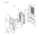
- Fig. 8 is an exploded perspective view of the second indoor unit according to the present invention.
- the second indoor unit 200 of the air conditioner includes: a front panel 201 forming a front appearance of the second indoor unit 200; a front frame 280 in which the front panel is fitted to thereby form a front surface; a blowing fan 235 formed at a rear side of the front frame 280, for introducing the indoor air; an orifice 240 formed at a rear side of the blowing fan 235, for guiding the direction of the air introduced by the rotation of the blowing fan; a heat exchanger 250 formed at a rear side of the orifice 240, for contacting with the introduced air to thereby decrease the temperature of the introduced air; and a base 260 formed at a rear side of the heat exchanger 250 and connected to the front frame 280.
- an outlet opening/closing unit 500 is provided between the front panel 210 and the front frame 280 so as to open/close the outlet port 281.
- the second indoor unit can be assembled in order of the front panel 201, the front frame 280, the blowing fan 235, the orifice 240, the heat exchanger 250 and the base 260.
- the orifice 240 includes: an air guide hole 245 for guiding the introduced air toward the blowing fan 235; an upper air guide 241 formed at an upper side so as to guide the indoor air introduced through the air guide hole 245 toward both sides; a lower air guide 242 formed at a lower side so as to guide downwards the indoor air introduced through the air guide 245; and a lower outlet door 243 for dispersedly discharging the air guided by the lower air guide 242 toward the interior.
- a motor for rotating the blowing fan 235 and an electronic component part 249 for controlling the driving of electronic components are further provided at an upper space between the front frame 280 and the orifice 240.
- a drain pan 270 is further provided at a lower side of the heat exchanger 250 so as to gather a condensate water formed on the surface of the heat exchanger 250.
- a pipe cover 290 for receiving a variety of pipes connected with the drain pan 270 and the second indoor unit 200 is provided at a lower side of the drain pan 270. In this manner, the second indoor unit of the air conditioner according to the present invention is provided.
- the front panel 201 is attached to the front surface of the second indoor unit 200, thereby forming an outer appearance of the second indoor unit elegantly.
- Windows 210 and 211 are formed at one side of the front panel 201 so as to display the operation and/or operational state of the second indoor unit 200.
- finishing materials may be used or a design is added. A detailed description of the front panel 201 will be described later.
- the front panel 201 is attached to the front frame 280 and a framework of the front frame 280 can be inclined at a predetermined angle.
- a side outlet port 281 and a lower outlet port 283 can be formed in at least one side of the framework so as to discharge the air, which is introduced into the second indoor unit 200 and cooled through the heat exchanger 250.
- the front panel 201 can be fixedly attached to the front frame 280.
- a hinge can be provided at one side so as to make the front panel 201 movable right and/or left, and the outlet port can be formed at the front side of the second indoor unit 200.
- blowing fan 235 is rotated by the motor attached to a rear side of the front frame 280, so that the indoor air is introduced inside the second indoor unit 200.
- At least one blowing fan 235 can be installed depending on size and use of the second indoor unit 200.
- the orifice 240 functions to guide a flow of the air introduced toward the blowing fan 235.
- a flowing direction of the air introduced through the guide hole 245 is determined by the air guides 241 and 242 and the air is discharged through the outlet ports 281 and 263.
- the air guide 241 can be formed in various shapes depending on the direction and number of the outlet port.
- a wind direction controller 244 and a safety net 246 are further provided.
- the wind direction controller 244 is attached to both sides of the orifice 240 and is rotating at a predetermined angle, thereby controlling the direction of the discharged cool air.
- the safety net 246 protects the user or children from the blowing fan 235 when they touches it.
- the heat exchanger 250 includes a heat exchange pipe, which is curved several times. A low temperature and low pressure refrigerant passing through an expander flows through the heat exchange pipe 251. Therefore, the air introduced into the second indoor unit 200 is deprived of heat while passing the heat exchanger 250, and thus becomes a low temperature state. During this process, moisture contained in the introduced air is cooled and thus condensed on the surface of the heat exchanger 250. A cooling effect becomes more excellent as an area of the heat exchanger 250 is wider. Therefore, the heat exchanger 250 can be formed in a flat rectangular shape or inclined at a predetermined angle.
- the drain pan 270 is formed at a lower side of the heat exchanger 250 so as to gather a condensate water formed on the surface of the heat exchanger 250 and prevent the condensate water from being leaked from the second indoor unit 200.
- the base 260 includes: an upper inlet port 261 formed at an upper side, for introducing the indoor air; and a central inlet port 262 formed at a central portion of the base 260.
- the shape and number of the inlet port can be freely selected depending on a volume and shape of the second indoor unit.
- a grill is formed at the inlet ports 261 and 262, with spaced apart by a predetermined interval and crossed with each other. Therefore, impurities contained in the indoor air introduced into the second indoor unit 200 are primarily filtered.
- a filter insertion hole 263 may be formed at one side of the base 260.
- a filter (not shown) for filtering impurities, such as dirt, contained in the introduced air, is inserted into the filter insertion hole 263. It is preferable that impurities is prevented from being attached to the surface of the heat exchanger 250 by inserting the filter between the base 260 and the heat exchanger 250.
- the filter insertion hole 263 may be an inlet port for the indoor air.
- the second indoor unit 200 can be freely installed at the corner of the wall by making the framework of the base 260 inclined at a predetermined angle. It is apparent that the inlet port can be formed at the sides. Also, it is apparent that a locking hole or locking groove can be formed at an edge of the base 260, so that the second indoor unit 200 can be attached.
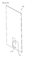
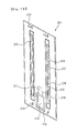
- Figs. 9 and 10 are a front view and a rear view of the front panel of the second indoor panel, respectively.
- the front panel 201 corresponds to the front surface of the second indoor unit and can be painted with various colors.
- the front panel 201 can be decorated with pictures or photographs.
- the front panel 201 includes a transparent operation display window 211 through which the screen displayed on the state display part of the second indoor unit 200 is shown, and a transparent display window 210 through which a screen displaying the character image is shown.
- the front panel 201 includes: a front frame coupling rib 216 protruded at a rear upper side with a predetermined length and connected to the front frame 280; and a front frame coupling protrusion 213 protruded at a rear lower side with a predetermined length and curved and extended downwards.
- the front frame coupling rib 216 is inserted into a front panel fitting groove (285, in Fig. 12) formed at an upper side of the front frame 280.
- the front frame coupling protrusion 213 is inserted into the front panel fixing member (286, in Fig. 12) mounted on a lower side of the front frame 280. In this manner, the front panel 201 can be fitted into the front frame 280.
- At least one shape reinforcing member 220 is attached vertically so as to maintain the shape of the front panel 201 and make the front panel 201 tolerable to an external force.
- the shape reinforcing member (refer to Fig. 9) is additionally attached. The shape reinforcing member 220 will be described later.
- At least one shape reinforcing member insertion rib 217 is formed along the side of the shape reinforcing member 220.
- the insertion rib 217 is formed at a height corresponding to a thickness of the shape reinforcing member 220.
- the insertion rib 217 is bent horizontally from an upper end and with a predetermined length, thereby fixing an upper surface of the shape reinforcing member 220.
- a shape reinforcing member guide rib 215 is formed at an opposite side to the insertion rib 217 and with the same length as the shape reinforcing member 220 so as to support the side of the shape reinforcing member 220.
- At least one shape reinforcing member coupling boss 216 is formed between the insertion rib 217 and the guide rib 215 so as to insert a coupling member connected to the shape reinforcing member 220.
- the coupling boss 216 is formed on a line of a shape reinforcing support rib 218 and with the same interval.
- the shape reinforcing support rib 218 is formed with the same height as the central portion of the shape reinforcing member 220.
- the support rib 218 functions to support the central portion of the shape reinforcing member 220.
- a display receiving surface 214 for receiving a state display part and a display part, which will be described later, is formed at a lower side of the front panel 201.
- Transparent windows 210 and 211 are formed to allow the user to view the screen displayed on the display part.
- Fig. 11 is a perspective view of a shape reinforcing member of the second indoor unit according to the present invention.
- the shape reinforcing member 220 is mounted to prevent the front panel 201 from being bent or to protect the front panel 201 from an external impact. Therefore, preferably, the shape reinforcing member 220 is made of metal or plastics maintaining a predetermined strength. Also, the shape reinforcing member 220 is raised in its center to a predetermined height and has on both ends a fitting part 222 bent horizontally, so that it may be stuck on the rear side of the front panel 201. A vertical cross section of the shape reinforcing member 220 is of a vertical step structure on its center as shown in the drawing, whereby the front panel 201 can endure impact applied from the outside.
- the fitting part 222 is fit in the shape reinforcing member insertion rib 217 formed on the rear side of the front panel 201. Also, at least one coupling member penetrating groove 221 for receiving a coupling member inserted into the shape reinforcing member coupling boss 216 is formed at the position that corresponds to the shape reinforcing member coupling boss 216 on the center of the shape reinforcing member 220.
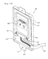
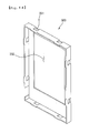
- Fig. 12 is a front perspective view of the front frame 201 according to the present invention.
- the front frame 280 into which the front panel 201 of the present invention is fitted has in its periphery a front panel fitting groove 285 for receiving the front frame coupling rib 212 formed on the upper side of the front panel 201.
- the front panel fixing member 286 for receiving the front frame coupling protrusion 213 formed on the lower end of the front panel 201 is formed on the lower end of the front frame. More specifically, the front panel fixing member 286 is inserted into the coupling boss 287 formed protruded on the front frame 280. Also, both sides of the front panel fixing member 266 are supported and fixed by a supporting rib 288 extended horizontally on the lower side of the front frame.
- a state display part 300 for displaying an operational state of the second indoor unit 200 is settled on the lower side of the front frame 280, and a display part 350 for displaying a character image so that an operational state of the second indoor unit 200 may be easily recognized by a user is settled on the upper part of the state display part 300.
- the state display part 300 is settled on a state display part mounting boss 230 formed on the front frame 280 and joined by a coupling member, and both sides of the state display part 300 are supported by a state display supporting rib 231.
- a groove instead of the state display part mounting boss 230 may be formed so that a coupling member may be inserted.
- the display part 350 may be mounted on the front frame 280 in the same manner as the state display part 300 is mounted.
- Fig. 13 is a front view of the state display part according to the present invention and Fig. 14 is a perspective view showing an upper case of the state display part.
- the state display part of the present invention is protected by a lower case 310 and an upper case 320.
- a PCB Print Circuit Board
- an LCD Liquid Crystal Display
- an operational state of the second indoor unit is settled on the upper side of the PCB 320.
- the PCB and the LCD window 330 are mutually connected, so that a signal and information provided from the PCB 320 is transferred to the LCD window 330 and a user can visually check an operational state.
- an operation button 321 by which a user can manually operate and a receiving part 322 through which a user can control the operational state using a remote controller are formed on the lower side of the PCB.
- the lower case 310 has a wire settling part 312 at the lower side of the PCB, and a wire 340 connected from the PCB is put in the inside of the wire settling part 312. Also, a wire passing groove 314 through which the wire 340 passes is formed on the lateral side of the wire settling part 312.
- a coupling part 311 extended with a predetermined length and a coupling groove 311 penetrated on a predetermined position of the coupling part are provided on the upper side and/or the lower side of the lower case 310. More specifically, a coupling member is inserted in a passing-through manner into the coupling groove 311 and the state display part mounting boss 230 formed on the front frame 280. Also, at least one hook 313 for joining to the upper case 320 are formed on the outer periphery of the lower case 310.
- At least one hook insertion hole 331 for inserting into the upper side of the lower case 310 and receiving the hook 313 on the outer periphery is formed on the upper case 320.
- an LCD window settling hole 332 to which the LCD window 330 is fit is provided to the central part.
- the LCD window 330 displays the operational state of the second indoor unit 200, and more specifically, displays an amount of cool air discharged from the second indoor unit 200, an indoor temperature and humidity, and an operation time.
- the state display part 300 receives a radio wave sent through a remote controller by a user, to display relevant information on the LCD window 330 in a digital manner, depending on the changing operational state. More specifically, the displaying manner may be realized by a number and may also by realized by an equalizer manner.
- Fig. 15 is a view showing an operation of the display part according to the present invention.
- the display part 350 of the present invention outputs a character image desired by a user or stored in advance in a storage medium of the apparatus.
- the display part 350 formed on the second indoor unit 200 may output an image realized in the same operation manner as the character image displayed on the display part 160.
- the display part 350 may include: a case 351; a PCB 352 settled on the inside of the case 351; an LCD window 353 settled on the upper part of the PCB 352; an operation button 355 formed on the lower end of the PCB 352 so that not only a user may manually operate the display part 350 and but also the operational state of the second indoor unit 200 may be automatically run depending on a set environment; and a wireless receiving part 357 for receiving an operation signal transmitted through a remote controller 710 by a user and receiving an AVATA-transmitting signal sent through a mobile means 700 such as a cellular phone by a user.
- a selection button 356 for setting or selecting a plurality of kinds of AVATAs, is additionally provided.
- the display part 350 is connected with a data inputting apparatus 720 as exemplified by a computer, so that various kinds of characters can be downloaded through the Internet.
- the display part 350 can be programmed in such a way that a current operational state of the indoor unit and a temperature may be announced in a voice at the same time a character may be displayed on the LCD window 353. Also, the voice is configured to guide the operational state of the second indoor unit 200 in a human voice through a speaker 730 connected with the controller.
- a memory chip 354 of a predetermined capacity capable of receiving and storing the AVATA character sent by a user, may be built in the PCB 352. More specifically, various kinds of character images existing in form of an electronic file may be downloaded through the data inputting apparatus 720 connected with the controlling part of the air conditioner or the display part 350, and may be stored in the memory chip 354.
- the character downloaded through the mobile means 700 such as a cellular phone by a user, may be received in a radio way by the receiving part 357 and stored in the memory chip 354. Further, a user may produce, in person, a character image of a proper shape using the data inputting apparatus 720 and store the same in the memory chip 354. As a result, for a means by which a user can input/store/select a character, more than one among a selection button 356 of an air conditioner itself, a remote controller 710, a data inputting apparatus 720, a mobile means 700, can be selectively used.
- the operational state of the air conditioner can be controlled from a remotely located area. Therefore, a user can control the air conditioner system including the second indoor unit 200 to operate through the Internet while a user is out, and control the operation of the second indoor unit 200 using a wireless telephone. Also, a user can use the display part 350 for an Internet screen as well as a means for showing the operational state of the second indoor unit 200, by connecting the display part 350 with the Internet. In other words, the Internet screen is displayed by pressing the selection button 356 of the display part 350, so that the display part 350 can be used as a means for watching a news.
- the apparatus for controlling the operational state of the second indoor unit 200 through the Internet and the wireless communication means can be mounted on the state display part 300.
- the joining manner of the state display part 300 can be applied, in the same way, to the manner in which the display part 350 is settled on the case and joined to the front frame 280.
- the second indoor unit 200 On the first place, if a user transmits an operation signal by pressing, in person, the operation button 355 or through the remote controller 710 and the receiving part 357 receives the operation signal, the second indoor unit 200 operates. Also, the moment the second indoor unit 200 operates, a power source is applied to the display part 350 and a specific character image stored in advance or input by a user, is displayed. For example, it is possible to have a character that have been sleeping wakes up. Also, simultaneously, it is possible to inform the operation of the second indoor unit 200 with a voice through the speaker 730 connected with the display part 350. Also, the voice may be downloaded through the mobile means 700 or the data inputting apparatus 720, or recorded and stored in the memory chip 354 by a user in person.
- the character may perform a proper gesture depending on an amount of air, an indoor temperature, humidity, or a voice informing such information may be announced through the speaker 730.
- a user can set in such a way that if a present temperature is below the proper temperature programmed in advance, the character may perform a gesture shivering with cold, and simultaneously, a guiding message informing that the indoor temperature is too low may be announced through the speaker.
- the second indoor unit 200 is turned off, the character may perform a gesture falling asleep and a guiding message informing that the operation of the second indoor unit 200 is stopped may be announced through the speaker 730.
- a user may arbitrarily select the kind of the AVATA using the selection button 356.
- Fig. 16 is a block diagram explaining a control state of the air conditioner according to the present invention.
- a key inputting part 31 with which a control state of the air conditioner is operated by a user a power source part 32 for applying a power source to the air conditioner; an data inputting apparatus 33 for inputting a specific character and a plurality of character images using the character, to the air conditioner; a controlling part 30 where a control state of the air conditioner is stored in a storing medium formed in the inside of the air conditioner and for controlling the operation of the air conditioner using the input information; an operational state display part 34 on which at least character image is displayed under the control of the controlling part 30; a voice outputting part 35 for outputting the operational state of the air conditioner in a voice under the control of the controlling part 30; a fan operating part 36 for controlling the operational state of the outdoor unit and/or the indoor unit, under the control of the controlling part 30; and a compressor operating part 37 for circulating a coolant.
- the key inputting part 31, which is a part with which a user operates the operational state of the air conditioner, may be at least one selected among a remote controller of the air conditioner, a button formed on the appearance of the apparatus, a computer system connected through wiring/wireless network.
- the data inputting part 33 is a device for generating or downloading a character and a plurality of character images where the specific character appears and transferring the same to the controlling part 30.
- a data inputting part 33 at least one among a computer, a mobile means, a remote controller, may be used.
- the operational state display part 34 formed on the air conditioner is a part through which the operational state of the air conditioner may be displayed to a user in an easy and simple manner with the character image displayed.
- the operational state display part 34 is realized by the LCD so that a user may recognize the character image in a convenient and beautiful manner.
- a user can recognize the operational state of the air conditioner in a more easy and convenient manner.
- a shape of the character image changes depending on the operational state of the air conditioner, a user can recognize the operational state of the air conditioner in even more easy and convenient manner.
- the voice outputting part 35 which is a part for outputting the operational state of the air conditioner in form of a voice, can output the operational state of the air conditioner in form of a voice depending on a user's desire.
- the fan operating part 36 and the compressor operating part 37 which are apparatus for circulating a coolant in the inside of the cooling cycle to get a coolant to pass through processes of compression, condensation, expansion, and evaporation in accordance with the operational state by a user, are on/off-controlled by the controlling part 30 depending on the operational state and the indoor temperature of the air conditioner.
- the air conditioner system of the present invention can be operated in three modes.
- a first mode is a character image uploading mode for uploading a character image into the controlling part 30 in the inside of the air conditioner using the data inputting part 33.
- a second mode is a character image display mode where the air conditioner system is operated by operation of the key inputting part 31 by a user and the character image is displayed on the operational state display part 34.
- a third mode is a character and a character image selecting mode for selecting a set of character images related to a specific character.
- the recognition of a user can be convenient even more. Also, since a specific character is selected in accordance with a taste of a user and a specific set of character images can be selected among a plurality of character images where the character is used, a user can display a character fit for a user's taste, on the air conditioner in a convenient manner. For an extreme example, a user's picture may be displayed.
- the character and the character image selecting mode is easily performed by cooperative operation of the key inputting part 31 and the controlling part 30. More specifically, after the process for selecting a character is performed, a specific character image is selected among a plurality of character images related to the selected character, for each operational state of the air conditioner. Of course, if a user desires, a specific character needs not to be used in a related set, for each operational state of the air conditioner, and other character image where other character is used, may be set for each operational state of the air conditioner.
- Fig. 17 is a flowchart explaining the character image uploading mode according to the spirit of the present invention.
- a user obtains a character and/or a character image by downloading through a network or by producing, in person, the character image (S11).
- the character image S11
- any type of method such as wiring/wireless network and a producing by a user, may be used without limitations.
- a plurality of characters, a plurality of character images where a pose, a background, a position, and a movement are different for each character may be stored in a set in the storing medium in the inside of the controlling part 30.
- a user uploads the generated character image to the controlling part 30 through the data inputting part 33 (S12).
- the uploading process can be easily performed through a LAN (Local Area Network) and wiring/wireless Internet.
- the character and the character image uploaded in this manner are stored in the storing medium of the controlling part 30 (S13), and upon calling by a user, one set of character images to which a specific character is applied, is called and used in the air conditioner.
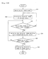
- Fig. 18 is a flowchart explaining the character image display mode of the air conditioner to which the spirit of the present invention is applied.
- the operation of the air conditioner is started by an input or reservation setting of a user (S21). If the operation of the air conditioner is started, one set of character images selected in advance by a user is called and a character image appropriate for a present state, initial operation of the air conditioner, is displayed on the operational state display part 34 on the first place (S22). If a selected character is absent at the present point of time, selection of a character may be automatically requested on the first place, or one set of character images designated from the time of manufacturing of the air conditioner, may be called.
- a character image of ended state is displayed (S26) and the operation of the air conditioner is ended.
- the process is moved to the step of judging a change of the operational state of the air conditioner (S23), and the process for changing the character image is repeated until the air conditioner is ended.
- a user sets a specific character image in advance, for each operational state of the air conditioner, in performing the character image display mode as described above, not only the character image included in one set related to a single character but also another character image where another character is used, may be displayed for each operational state of the air conditioner in accordance with a taste of a user.
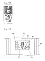
- Fig. 19 shows a character image displayed in the start/stop mode of the operation of the air conditioner.
- Fig. 20 shows a character image displayed in the cooling operation mode of the air conditioner. Referring to Fig. 20, upon the general cooling operation, the character image on the upper side is displayed and upon a power cooling operation, the character image on the lower side is displayed.
- Fig. 21 shows a character image displayed in the dehumidifying operation mode of the air conditioner. Referring to Fig. 21, upon the dehumidifying operation mode, the character images on the upper side and on the lower side are alternately displayed.
- Fig. 22 shows a character image displayed in the artificial intelligence operation mode of the air conditioner. Referring to Fig. 22, upon the artificial intelligence operation mode, the character images on the upper side and on the lower side are alternately displayed.
- Fig. 23 shows a character image displayed in the plasma clean operation mode of the air conditioner. Referring to Fig. 23, upon the plasma clean operation mode, the character images on the upper side and on the lower side are alternately displayed.
- the character image displayed on the operational state display part 34 is varied in detail in accordance with the change of the operational state of the air conditioner. Since the displayed character is changed in this manner, a user can check the operational state of the air conditioner in a more easy manner. Also, by the display parts 160 and 350 formed on the front of the air conditioner, the air conditioner can be quality-enhanced and a taste of a user can be satisfied even more.
- the second embodiment of the present invention is the same in most part as the first embodiment. Only difference is that the display parts 160 and 350 on which at least a character image is displayed and the state display parts 170 and 300 on which the operational state of the air conditioner is displayed with a number or an arrow, are not formed separately but one or both two are displayed on a single LCD window by a selection of a user.
- the display parts 160 and 350, and the state display parts 170 and 300 are separately formed on both the first indoor unit 100 and the second indoor unit 200.
- a state that a character image is selectively displayed on a single display part by a selection of a user for example, the display part of the first embodiment
- a state that the operational state of the air conditioner is displayed with letters for example, the state display part of the first embodiment
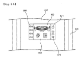
- Figs. 24 and 25 show the operational state of the display part.
- Fig. 24 shows that the character image is displayed on the display part and
- FIG. 25 shows the operational state of the air conditioner is displayed on the display part.
- a front panel 810 formed on a front of the air conditioner; a side panel 820 formed on the side of the air conditioner; a display window 860 formed on the front panel 810; an operation button 880 formed on one side of the display window 860, for operating the operational state of the air conditioner; a selection button 871 formed on the other side of the display window 860, for switching a screen displayed on the display window 860, into a display part where a character image is displayed or a state display part where the operational state of the air conditioner is displayed with letters; and a character setting button 872 for selecting the kind of a character or the kind of a character image.
- the LCD is preferably used as the first embodiment.
- the selection button 871 will be described in detail.
- the display window 860 operates as the display part 861 where the character image is displayed (refer to FIG. 24) or operates as the state display part 862 where the operational state of the air conditioner is displayed with letters (refer to FIG. 25).
- the display part 861 and the state display part 862 can be all displayed.
- the character setting button 872 it is possible to have a specific kind of characters and a specific kind of character images selected if the character setting button 872 is pressed. Also, in case a plurality of character setting buttons 872 is provided, a button for selecting a character and a button for selecting a character image can be separately provided, for each kind of buttons. Particularly, though not described in the first embodiment, the character setting button 872 will be easily realized also in the first embodiment. Also, if the character setting button 872 is not provided, the kind of the character and the kind of the character image may be easily selected together with the gesture input from the data inputting part 33.
- the present invention is characterized in that a predetermined display window is realized on the front of the air conditioner and a character image in which a predetermined character image is used, is displayed on the display window. Also, the present invention is characterized in that a user can use the air conditioner in a more convenient manner thanks to the character and the character image related to the character.
- the air conditioner capable of improving the user's recognizability according to the present invention can have various form in its embodiments.
- the spirit of the present invention can be applied not only to the air conditioner that has been described by the detailed embodiment, but also to other electronic appliances such as a cooking apparatus and a refrigerator, with change in its form in a convenient manner.
- the operational state of the air conditioner can be displayed by changing a pose, a position, a background, and a behavior of the character.
- the character image displayed on the display part not only the character image where the character is used, but also a character of a representative shape may be constantly displayed regardless of the operational state of the air conditioner. In case of the air conditioner, it will be preferable that a character that can emphasize coolness such as a penguin is selected.
- a character image understandable as the relevant operational state depending on the operational state of the air conditioner is displayed on one side of the air conditioner, so that a user can understand the operational state of the air conditioner in a convenient manner, without looking at the state display part displayed with letters.
- the present invention uses a character of a beautiful design besides the state display part displayed with letters of the conventional stiff image, thereby possibly obtaining more better visual effect. Accordingly, a user's taste can be promoted even more.
- a user can produce, in person, a character desired by a user, obtain various characters and character images where the character is used through various communication media, store in the storing medium in the inside of the air conditioner, and use the same. Therefore, since a user who makes use of the air conditioner can newly display a new character and/or a new character image at any time when a user desires or is tired of the existing character, the present invention has an effect that a user can use the air conditioner for a more longer time and a user can the air conditioner as if it were a newly purchased apparatus at any time when a user desires.
- the present invention additionally includes a voice outputting part for displaying the operation of the air conditioner, so that a voice message is properly output for each operational state of the air conditioner. Therefore, there is a strong point that a remotely located user or even the blind can use the air conditioner in a more convenient manner.
- the character as a trademark can enhance a brand image of the manufacturing company and in case the character is used for an advertising means, the character can function as a means for obtaining advertisement profit.
Applications Claiming Priority (2)
| Application Number | Priority Date | Filing Date | Title |
|---|---|---|---|
| KR1020030083541A KR100626443B1 (ko) | 2003-11-24 | 2003-11-24 | 공기조화기의 실내기 |
| KR2003083541 | 2003-11-24 |
Publications (3)
| Publication Number | Publication Date |
|---|---|
| EP1533576A2 true EP1533576A2 (fr) | 2005-05-25 |
| EP1533576A3 EP1533576A3 (fr) | 2006-08-23 |
| EP1533576B1 EP1533576B1 (fr) | 2015-09-16 |
Family
ID=36609125
Family Applications (1)
| Application Number | Title | Priority Date | Filing Date |
|---|---|---|---|
| EP04255802.3A Not-in-force EP1533576B1 (fr) | 2003-11-24 | 2004-09-23 | Dispositif de conditionnement d'air avec une meilleure perception d'utilisateur |
Country Status (10)
| Country | Link |
|---|---|
| US (1) | US7640757B2 (fr) |
| EP (1) | EP1533576B1 (fr) |
| JP (1) | JP4649166B2 (fr) |
| KR (1) | KR100626443B1 (fr) |
| CN (2) | CN2752652Y (fr) |
| AU (1) | AU2004290768B2 (fr) |
| BR (1) | BRPI0416420A (fr) |
| ES (1) | ES2548565T3 (fr) |
| WO (1) | WO2005050096A1 (fr) |
| ZA (1) | ZA200603703B (fr) |
Cited By (9)
| Publication number | Priority date | Publication date | Assignee | Title |
|---|---|---|---|---|
| WO2006135167A2 (fr) | 2005-06-17 | 2006-12-21 | Lg Electronics Inc. | Conditionneur d'air |
| WO2007018357A2 (fr) * | 2005-08-10 | 2007-02-15 | Lg Electronics Inc. | Climatiseur |
| EP1686326A3 (fr) * | 2004-12-30 | 2008-02-13 | Lg Electronics Inc. | Dispositif d'affichage d'un climatiseur |
| WO2008018678A2 (fr) | 2006-08-08 | 2008-02-14 | Lg Electronics, Inc. | Dispositif de climatisation |
| EP1949001A2 (fr) * | 2005-10-24 | 2008-07-30 | LG Electronics Inc. | Climatiseur et son procede de controle |
| EP2045541A1 (fr) | 2007-10-02 | 2009-04-08 | LG Electronics Inc. | Dispositif de contrôle pour climatiseur |
| CN102374628A (zh) * | 2010-08-12 | 2012-03-14 | 苏州三星电子有限公司 | 立柜式空调器用出风装置 |
| EP2982910A1 (fr) * | 2014-08-06 | 2016-02-10 | Mitsubishi Electric Corporation | Unite interieure de climatiseur |
| EP3056832A4 (fr) * | 2013-10-10 | 2017-06-14 | Daikin Industries, Ltd. | Conditionneur d'air |
Families Citing this family (85)
| Publication number | Priority date | Publication date | Assignee | Title |
|---|---|---|---|---|
| WO2004106811A1 (fr) * | 2003-05-27 | 2004-12-09 | Xiaosong Xiao | Conditionneur d'air monobloc |
| KR100626443B1 (ko) * | 2003-11-24 | 2006-09-20 | 엘지전자 주식회사 | 공기조화기의 실내기 |
| CN100505796C (zh) * | 2004-11-24 | 2009-06-24 | 中兴通讯股份有限公司 | 一种手机显示时间的方法 |
| KR20060093985A (ko) * | 2005-02-23 | 2006-08-28 | 엘지전자 주식회사 | 공기 조화기 |
| KR101054623B1 (ko) * | 2005-03-09 | 2011-08-04 | 엘지전자 주식회사 | 공기 조화기 |
| KR101221705B1 (ko) * | 2005-06-03 | 2013-01-15 | 엘지전자 주식회사 | 공기조화기 |
| KR101216261B1 (ko) * | 2005-08-10 | 2012-12-28 | 엘지전자 주식회사 | 공기조화기 |
| KR100776429B1 (ko) * | 2005-09-13 | 2007-11-16 | 엘지전자 주식회사 | 공기조화기의 제어방법 |
| KR100756698B1 (ko) * | 2005-10-05 | 2007-09-07 | 엘지전자 주식회사 | 다중 표시부를 지닌 냉장고 |
| AU2006291683B2 (en) | 2005-09-16 | 2010-08-19 | Lg Electronics Inc. | Refrigerator |
| KR101315630B1 (ko) * | 2006-01-18 | 2013-10-08 | 엘지전자 주식회사 | 공기조화기의 실내기 |
| AU2006337754B2 (en) * | 2006-02-07 | 2010-02-18 | Lg Electronics Inc. | Indoor unit of air conditioner |
| WO2008147058A2 (fr) * | 2007-05-25 | 2008-12-04 | Lg Electronics Inc. | Dispositif d'éclairage pour réfrigérateur et procédé de commande de celui-ci |
| KR101404106B1 (ko) * | 2007-10-24 | 2014-06-05 | 엘지전자 주식회사 | 공기조화장치용 제어장치 |
| US8725298B2 (en) | 2008-10-27 | 2014-05-13 | Lennox Industries, Inc. | Alarm and diagnostics system and method for a distributed architecture heating, ventilation and conditioning network |
| US8255086B2 (en) | 2008-10-27 | 2012-08-28 | Lennox Industries Inc. | System recovery in a heating, ventilation and air conditioning network |
| US8655491B2 (en) | 2008-10-27 | 2014-02-18 | Lennox Industries Inc. | Alarm and diagnostics system and method for a distributed architecture heating, ventilation and air conditioning network |
| US9325517B2 (en) | 2008-10-27 | 2016-04-26 | Lennox Industries Inc. | Device abstraction system and method for a distributed-architecture heating, ventilation and air conditioning system |
| US8774210B2 (en) | 2008-10-27 | 2014-07-08 | Lennox Industries, Inc. | Communication protocol system and method for a distributed-architecture heating, ventilation and air conditioning network |
| US8433446B2 (en) | 2008-10-27 | 2013-04-30 | Lennox Industries, Inc. | Alarm and diagnostics system and method for a distributed-architecture heating, ventilation and air conditioning network |
| US8744629B2 (en) | 2008-10-27 | 2014-06-03 | Lennox Industries Inc. | System and method of use for a user interface dashboard of a heating, ventilation and air conditioning network |
| US8548630B2 (en) | 2008-10-27 | 2013-10-01 | Lennox Industries, Inc. | Alarm and diagnostics system and method for a distributed-architecture heating, ventilation and air conditioning network |
| US9678486B2 (en) | 2008-10-27 | 2017-06-13 | Lennox Industries Inc. | Device abstraction system and method for a distributed-architecture heating, ventilation and air conditioning system |
| US9268345B2 (en) | 2008-10-27 | 2016-02-23 | Lennox Industries Inc. | System and method of use for a user interface dashboard of a heating, ventilation and air conditioning network |
| US8239066B2 (en) | 2008-10-27 | 2012-08-07 | Lennox Industries Inc. | System and method of use for a user interface dashboard of a heating, ventilation and air conditioning network |
| US8994539B2 (en) | 2008-10-27 | 2015-03-31 | Lennox Industries, Inc. | Alarm and diagnostics system and method for a distributed-architecture heating, ventilation and air conditioning network |
| US8564400B2 (en) | 2008-10-27 | 2013-10-22 | Lennox Industries, Inc. | Communication protocol system and method for a distributed-architecture heating, ventilation and air conditioning network |
| US9261888B2 (en) | 2008-10-27 | 2016-02-16 | Lennox Industries Inc. | System and method of use for a user interface dashboard of a heating, ventilation and air conditioning network |
| US9651925B2 (en) | 2008-10-27 | 2017-05-16 | Lennox Industries Inc. | System and method for zoning a distributed-architecture heating, ventilation and air conditioning network |
| US8762666B2 (en) | 2008-10-27 | 2014-06-24 | Lennox Industries, Inc. | Backup and restoration of operation control data in a heating, ventilation and air conditioning network |
| US8655490B2 (en) | 2008-10-27 | 2014-02-18 | Lennox Industries, Inc. | System and method of use for a user interface dashboard of a heating, ventilation and air conditioning network |
| US8543243B2 (en) | 2008-10-27 | 2013-09-24 | Lennox Industries, Inc. | System and method of use for a user interface dashboard of a heating, ventilation and air conditioning network |
| US8295981B2 (en) | 2008-10-27 | 2012-10-23 | Lennox Industries Inc. | Device commissioning in a heating, ventilation and air conditioning network |
| US8560125B2 (en) | 2008-10-27 | 2013-10-15 | Lennox Industries | Communication protocol system and method for a distributed-architecture heating, ventilation and air conditioning network |
| US8788100B2 (en) | 2008-10-27 | 2014-07-22 | Lennox Industries Inc. | System and method for zoning a distributed-architecture heating, ventilation and air conditioning network |
| US8463442B2 (en) | 2008-10-27 | 2013-06-11 | Lennox Industries, Inc. | Alarm and diagnostics system and method for a distributed architecture heating, ventilation and air conditioning network |
| US8600558B2 (en) | 2008-10-27 | 2013-12-03 | Lennox Industries Inc. | System recovery in a heating, ventilation and air conditioning network |
| US9152155B2 (en) | 2008-10-27 | 2015-10-06 | Lennox Industries Inc. | Device abstraction system and method for a distributed-architecture heating, ventilation and air conditioning system |
| US8600559B2 (en) | 2008-10-27 | 2013-12-03 | Lennox Industries Inc. | Method of controlling equipment in a heating, ventilation and air conditioning network |
| US8437877B2 (en) | 2008-10-27 | 2013-05-07 | Lennox Industries Inc. | System recovery in a heating, ventilation and air conditioning network |
| US8437878B2 (en) | 2008-10-27 | 2013-05-07 | Lennox Industries Inc. | Alarm and diagnostics system and method for a distributed architecture heating, ventilation and air conditioning network |
| US8452456B2 (en) | 2008-10-27 | 2013-05-28 | Lennox Industries Inc. | System and method of use for a user interface dashboard of a heating, ventilation and air conditioning network |
| US8855825B2 (en) | 2008-10-27 | 2014-10-07 | Lennox Industries Inc. | Device abstraction system and method for a distributed-architecture heating, ventilation and air conditioning system |
| US8442693B2 (en) | 2008-10-27 | 2013-05-14 | Lennox Industries, Inc. | System and method of use for a user interface dashboard of a heating, ventilation and air conditioning network |
| US8977794B2 (en) | 2008-10-27 | 2015-03-10 | Lennox Industries, Inc. | Communication protocol system and method for a distributed-architecture heating, ventilation and air conditioning network |
| US9632490B2 (en) | 2008-10-27 | 2017-04-25 | Lennox Industries Inc. | System and method for zoning a distributed architecture heating, ventilation and air conditioning network |
| US8874815B2 (en) | 2008-10-27 | 2014-10-28 | Lennox Industries, Inc. | Communication protocol system and method for a distributed architecture heating, ventilation and air conditioning network |
| US9432208B2 (en) | 2008-10-27 | 2016-08-30 | Lennox Industries Inc. | Device abstraction system and method for a distributed architecture heating, ventilation and air conditioning system |
| US8352081B2 (en) | 2008-10-27 | 2013-01-08 | Lennox Industries Inc. | Communication protocol system and method for a distributed-architecture heating, ventilation and air conditioning network |
| US8661165B2 (en) | 2008-10-27 | 2014-02-25 | Lennox Industries, Inc. | Device abstraction system and method for a distributed architecture heating, ventilation and air conditioning system |
| US8615326B2 (en) | 2008-10-27 | 2013-12-24 | Lennox Industries Inc. | System and method of use for a user interface dashboard of a heating, ventilation and air conditioning network |
| US8802981B2 (en) | 2008-10-27 | 2014-08-12 | Lennox Industries Inc. | Flush wall mount thermostat and in-set mounting plate for a heating, ventilation and air conditioning system |
| US8463443B2 (en) | 2008-10-27 | 2013-06-11 | Lennox Industries, Inc. | Memory recovery scheme and data structure in a heating, ventilation and air conditioning network |
| US8892797B2 (en) | 2008-10-27 | 2014-11-18 | Lennox Industries Inc. | Communication protocol system and method for a distributed-architecture heating, ventilation and air conditioning network |
| US8452906B2 (en) | 2008-10-27 | 2013-05-28 | Lennox Industries, Inc. | Communication protocol system and method for a distributed-architecture heating, ventilation and air conditioning network |
| US9377768B2 (en) | 2008-10-27 | 2016-06-28 | Lennox Industries Inc. | Memory recovery scheme and data structure in a heating, ventilation and air conditioning network |
| US8694164B2 (en) | 2008-10-27 | 2014-04-08 | Lennox Industries, Inc. | Interactive user guidance interface for a heating, ventilation and air conditioning system |
| US8798796B2 (en) | 2008-10-27 | 2014-08-05 | Lennox Industries Inc. | General control techniques in a heating, ventilation and air conditioning network |
| US8352080B2 (en) | 2008-10-27 | 2013-01-08 | Lennox Industries Inc. | Communication protocol system and method for a distributed-architecture heating, ventilation and air conditioning network |
| US9075901B2 (en) * | 2008-12-15 | 2015-07-07 | International Business Machines Corporation | System and method to visualize activities through the use of avatars |
| USD648641S1 (en) | 2009-10-21 | 2011-11-15 | Lennox Industries Inc. | Thin cover plate for an electronic system controller |
| USD648642S1 (en) | 2009-10-21 | 2011-11-15 | Lennox Industries Inc. | Thin cover plate for an electronic system controller |
| US8260444B2 (en) | 2010-02-17 | 2012-09-04 | Lennox Industries Inc. | Auxiliary controller of a HVAC system |
| EP2570740B1 (fr) * | 2010-05-12 | 2019-02-27 | Mitsubishi Electric Corporation | Appareil de climatisation |
| KR101800887B1 (ko) * | 2010-12-16 | 2017-11-23 | 엘지전자 주식회사 | 네트워크 시스템 |
| DE102012202037A1 (de) * | 2012-02-10 | 2013-08-14 | BSH Bosch und Siemens Hausgeräte GmbH | Haushaltsgerät mit einer Displayeinrichtung und Verfahren zum Betreiben einer Displayeinrichtung eines Haushaltsgeräts |
| KR101482139B1 (ko) * | 2012-11-12 | 2015-01-14 | 엘지전자 주식회사 | 공기조화기용 제어장치 및 그 동작방법 |
| KR101517084B1 (ko) | 2012-11-12 | 2015-05-04 | 엘지전자 주식회사 | 공기조화기용 제어장치 |
| KR101974368B1 (ko) * | 2013-04-19 | 2019-05-02 | 삼성전자주식회사 | 가전기기 및 그 제어방법 |
| CN104422059A (zh) * | 2013-08-20 | 2015-03-18 | 广东美的制冷设备有限公司 | 根据用户手势特征控制空调器导风的遥控器及其方法 |
| KR102149198B1 (ko) * | 2013-11-25 | 2020-08-28 | 엘지전자 주식회사 | 공기 조화기 |
| US10305698B2 (en) | 2013-12-19 | 2019-05-28 | Electrolux Home Products, Inc. | System, method, apparatus, and computer program product for customizing an appliance display |
| USD788278S1 (en) * | 2015-02-13 | 2017-05-30 | Samsung Electronics Co., Ltd. | Dehumidifier |
| WO2018048312A1 (fr) | 2016-09-06 | 2018-03-15 | Powerbyproxi Limited | Émetteur de puissance inductive |
| JP2020134019A (ja) * | 2019-02-20 | 2020-08-31 | 株式会社富士通ゼネラル | 室外機 |
| JP2020134020A (ja) * | 2019-02-20 | 2020-08-31 | 株式会社富士通ゼネラル | 室外機 |
| CN110822647B (zh) * | 2019-11-25 | 2021-12-17 | 广东美的制冷设备有限公司 | 空调器的控制方法、空调器及存储介质 |
| CN110822649B (zh) * | 2019-11-25 | 2021-12-17 | 广东美的制冷设备有限公司 | 空调器的控制方法、空调器及存储介质 |
| CN110822641A (zh) * | 2019-11-25 | 2020-02-21 | 广东美的制冷设备有限公司 | 空调器及其控制方法、装置和可读存储介质 |
| CN110822648B (zh) * | 2019-11-25 | 2021-12-17 | 广东美的制冷设备有限公司 | 空调器及其控制方法、计算机可读存储介质 |
| CN110822646B (zh) * | 2019-11-25 | 2021-12-17 | 广东美的制冷设备有限公司 | 空调器的控制方法、空调器及存储介质 |
| CN110822661B (zh) * | 2019-11-25 | 2021-12-17 | 广东美的制冷设备有限公司 | 空调器的控制方法、空调器及存储介质 |
| CN110822643B (zh) * | 2019-11-25 | 2021-12-17 | 广东美的制冷设备有限公司 | 空调器及其控制方法和计算机存储介质 |
| CN111023399A (zh) * | 2019-12-30 | 2020-04-17 | 宁波奥克斯电气股份有限公司 | Vr系统、基于vr的空调控制方法及空调模拟方法 |
| JP7116338B2 (ja) * | 2020-12-24 | 2022-08-10 | ダイキン工業株式会社 | 情報引き継ぎシステム、第2基板、空気調和装置、及び情報引き継ぎ方法 |
Citations (4)
| Publication number | Priority date | Publication date | Assignee | Title |
|---|---|---|---|---|
| EP1092927A2 (fr) * | 1999-10-14 | 2001-04-18 | Sharp Kabushiki Kaisha | Installation de climatisation avec dispositif d'humidification/déshumidification |
| JP2002011275A (ja) * | 2000-06-29 | 2002-01-15 | Hitachi Ltd | 表示手段を備えた家庭用電気機器及びその操作方法 |
| EP1275909A1 (fr) * | 2000-04-20 | 2003-01-15 | Daikin Industries, Ltd. | Systeme de surveillance de climatiseur |
| WO2003014628A2 (fr) * | 2001-08-11 | 2003-02-20 | Lg Electronics Inc. | Conditionneur d'air |
Family Cites Families (23)
| Publication number | Priority date | Publication date | Assignee | Title |
|---|---|---|---|---|
| JPS5979746A (ja) | 1982-10-30 | 1984-05-09 | Mitsubishi Heavy Ind Ltd | 加硫機用制御装置 |
| JPS5979746U (ja) * | 1982-11-19 | 1984-05-30 | 三洋電機株式会社 | 空気調和機の表示装置 |
| JPH0213752A (ja) * | 1988-07-01 | 1990-01-18 | Sanyo Electric Co Ltd | 空気調和機のリモートコントローラ |
| US5453939A (en) * | 1992-09-16 | 1995-09-26 | Caterpillar Inc. | Computerized diagnostic and monitoring system |
| JPH09170802A (ja) * | 1995-12-19 | 1997-06-30 | Toshiba Corp | 空気調和機のリモートコントロール装置 |
| KR100241622B1 (ko) * | 1997-06-12 | 2000-03-02 | 오상수 | 패키지 에어컨의 동화상 표시장치 |
| US6243645B1 (en) * | 1997-11-04 | 2001-06-05 | Seiko Epson Corporation | Audio-video output device and car navigation system |
| JPH11159848A (ja) * | 1997-11-28 | 1999-06-15 | Matsushita Electric Ind Co Ltd | 空気調和機の液晶表示装置 |
| JPH11230648A (ja) * | 1998-02-13 | 1999-08-27 | Matsushita Electric Ind Co Ltd | 可燃性冷媒を用いた冷凍機器の冷媒漏洩警報装置 |
| JP3441971B2 (ja) * | 1998-07-02 | 2003-09-02 | 松下電器産業株式会社 | 多機能装置のデモンストレーションシステム |
| JP2000076487A (ja) | 1998-09-03 | 2000-03-14 | Sony Corp | 情報処理装置および方法、並びに提供媒体 |
| JP4183051B2 (ja) * | 1998-09-10 | 2008-11-19 | 東芝キヤリア株式会社 | リモートコントロール装置 |
| JP4453237B2 (ja) * | 1999-12-14 | 2010-04-21 | ソニー株式会社 | デジタルデータ記録装置 |
| JP2001272089A (ja) | 2000-03-29 | 2001-10-05 | Toshiba Kyaria Kk | 空気調和機 |
| PT1681066E (pt) * | 2000-05-18 | 2009-10-28 | Sharp Kk | Método de esterilização |
| KR20020031229A (ko) * | 2000-10-23 | 2002-05-01 | 구자홍 | 공기조화기용 디스플레이 장치 |
| JP4395687B2 (ja) * | 2000-12-20 | 2010-01-13 | ソニー株式会社 | 情報処理装置 |
| MY136575A (en) * | 2001-06-19 | 2008-10-31 | Lg Electronics Inc | Air conditioner |
| JP3769216B2 (ja) | 2001-09-19 | 2006-04-19 | 株式会社ほんぽ | 昆布塩の製造方法 |
| JP2003248841A (ja) | 2001-12-20 | 2003-09-05 | Matsushita Electric Ind Co Ltd | バーチャルテレビ通話装置 |
| KR20030088694A (ko) * | 2002-05-14 | 2003-11-20 | (주) 인포웹 | 동시표현이 가능한 아바타와 이것을 적용한아이템/개인가상공간 구현 방법 |
| US7249466B2 (en) * | 2003-09-04 | 2007-07-31 | Lg Electronics Inc. | Indoor unit in air conditioner |
| KR100626443B1 (ko) * | 2003-11-24 | 2006-09-20 | 엘지전자 주식회사 | 공기조화기의 실내기 |
-
2003
- 2003-11-24 KR KR1020030083541A patent/KR100626443B1/ko not_active IP Right Cessation
-
2004
- 2004-08-27 WO PCT/KR2004/002156 patent/WO2005050096A1/fr active Application Filing
- 2004-08-27 BR BRPI0416420-2A patent/BRPI0416420A/pt not_active IP Right Cessation
- 2004-08-27 AU AU2004290768A patent/AU2004290768B2/en not_active Ceased
- 2004-09-23 ES ES04255802.3T patent/ES2548565T3/es active Active
- 2004-09-23 EP EP04255802.3A patent/EP1533576B1/fr not_active Not-in-force
- 2004-10-05 US US10/957,668 patent/US7640757B2/en not_active Expired - Fee Related
- 2004-10-19 JP JP2004304620A patent/JP4649166B2/ja not_active Expired - Fee Related
- 2004-11-24 CN CNU2004200573344U patent/CN2752652Y/zh not_active Expired - Lifetime
- 2004-11-24 CN CNB200410095362XA patent/CN100343587C/zh not_active Expired - Fee Related
-
2006
- 2006-05-10 ZA ZA200603703A patent/ZA200603703B/en unknown
Patent Citations (4)
| Publication number | Priority date | Publication date | Assignee | Title |
|---|---|---|---|---|
| EP1092927A2 (fr) * | 1999-10-14 | 2001-04-18 | Sharp Kabushiki Kaisha | Installation de climatisation avec dispositif d'humidification/déshumidification |
| EP1275909A1 (fr) * | 2000-04-20 | 2003-01-15 | Daikin Industries, Ltd. | Systeme de surveillance de climatiseur |
| JP2002011275A (ja) * | 2000-06-29 | 2002-01-15 | Hitachi Ltd | 表示手段を備えた家庭用電気機器及びその操作方法 |
| WO2003014628A2 (fr) * | 2001-08-11 | 2003-02-20 | Lg Electronics Inc. | Conditionneur d'air |
Non-Patent Citations (2)
| Title |
|---|
| PATENT ABSTRACTS OF JAPAN vol. 1999, no. 11, 30 September 1999 (1999-09-30) -& JP 11 159848 A (MATSUSHITA ELECTRIC IND CO LTD), 15 June 1999 (1999-06-15) * |
| PATENT ABSTRACTS OF JAPAN vol. 2002, no. 05, 3 May 2002 (2002-05-03) -& JP 2002 011275 A (HITACHI LTD), 15 January 2002 (2002-01-15) * |
Cited By (18)
| Publication number | Priority date | Publication date | Assignee | Title |
|---|---|---|---|---|
| EP1686326A3 (fr) * | 2004-12-30 | 2008-02-13 | Lg Electronics Inc. | Dispositif d'affichage d'un climatiseur |
| EP1891381A4 (fr) * | 2005-06-17 | 2009-12-02 | Lg Electronics Inc | Conditionneur d'air |
| EP1891381A2 (fr) * | 2005-06-17 | 2008-02-27 | LG Electronics Inc. | Conditionneur d'air |
| WO2006135167A2 (fr) | 2005-06-17 | 2006-12-21 | Lg Electronics Inc. | Conditionneur d'air |
| WO2007018357A2 (fr) * | 2005-08-10 | 2007-02-15 | Lg Electronics Inc. | Climatiseur |
| WO2007018357A3 (fr) * | 2005-08-10 | 2007-05-03 | Lg Electronics Inc | Climatiseur |
| WO2007049849A3 (fr) * | 2005-10-24 | 2009-05-07 | Lg Electronics Inc | Climatiseur et son procede de controle |
| EP1949001A2 (fr) * | 2005-10-24 | 2008-07-30 | LG Electronics Inc. | Climatiseur et son procede de controle |
| EP1949001A4 (fr) * | 2005-10-24 | 2009-11-25 | Lg Electronics Inc | Climatiseur et son procede de controle |
| EP2049843A2 (fr) * | 2006-08-08 | 2009-04-22 | LG Electronics, Inc. | Dispositif de climatisation |
| WO2008018678A2 (fr) | 2006-08-08 | 2008-02-14 | Lg Electronics, Inc. | Dispositif de climatisation |
| EP2049843A4 (fr) * | 2006-08-08 | 2010-03-24 | Lg Electronics Inc | Dispositif de climatisation |
| EP2045541A1 (fr) | 2007-10-02 | 2009-04-08 | LG Electronics Inc. | Dispositif de contrôle pour climatiseur |
| CN102374628A (zh) * | 2010-08-12 | 2012-03-14 | 苏州三星电子有限公司 | 立柜式空调器用出风装置 |
| EP3056832A4 (fr) * | 2013-10-10 | 2017-06-14 | Daikin Industries, Ltd. | Conditionneur d'air |
| EP2982910A1 (fr) * | 2014-08-06 | 2016-02-10 | Mitsubishi Electric Corporation | Unite interieure de climatiseur |
| US20160040901A1 (en) * | 2014-08-06 | 2016-02-11 | Mitsubishi Electric Corporation | Indoor unit of air-conditioning apparatus |
| US9523511B2 (en) | 2014-08-06 | 2016-12-20 | Mitsubishi Electric Corporation | Indoor unit of air-conditioning apparatus |
Also Published As
| Publication number | Publication date |
|---|---|
| EP1533576A3 (fr) | 2006-08-23 |
| CN1621750A (zh) | 2005-06-01 |
| EP1533576B1 (fr) | 2015-09-16 |
| KR20050049801A (ko) | 2005-05-27 |
| AU2004290768A1 (en) | 2005-06-02 |
| US20050109048A1 (en) | 2005-05-26 |
| KR100626443B1 (ko) | 2006-09-20 |
| US7640757B2 (en) | 2010-01-05 |
| ES2548565T3 (es) | 2015-10-19 |
| WO2005050096A1 (fr) | 2005-06-02 |
| JP2005156142A (ja) | 2005-06-16 |
| ZA200603703B (en) | 2007-09-26 |
| BRPI0416420A (pt) | 2007-01-16 |
| CN2752652Y (zh) | 2006-01-18 |
| AU2004290768B2 (en) | 2008-10-16 |
| CN100343587C (zh) | 2007-10-17 |
| JP4649166B2 (ja) | 2011-03-09 |
Similar Documents
| Publication | Publication Date | Title |
|---|---|---|
| US7640757B2 (en) | Air conditioner having an enhanced user perception | |
| EP1533577B1 (fr) | Conditionneur d'air avec un moyen d'affichage | |
| AU2004318831B2 (en) | Air conditioner | |
| EP1891381B1 (fr) | Conditionneur d'air | |
| ZA200603705B (en) | Air conditioner | |
| CN101086376A (zh) | 空调机的智能显示与用户沟通方法 | |
| KR20070077243A (ko) | 공기조화기 | |
| MXPA06005829A (en) | Air conditioner having an enhanced user perception | |
| MXPA06005828A (en) | Air conditioner having an enhanced user perception | |
| MXPA06005832A (en) | Air conditioner | |
| KR101070135B1 (ko) | 공기 조화기 실내기의 표시부 장착구조 | |
| KR20070028632A (ko) | 공기조화기의 부저음 발생장치 및 방법 | |
| KR20060131415A (ko) | 공기조화기 | |
| KR20050089414A (ko) | 공기 조화기 실내기의 전면 패널 장착구조 | |
| KR100543325B1 (ko) | 공기조화기 및 그 제어 방법 | |
| KR20050089413A (ko) | 공기 조화기 실내기의 전면 패널 장착구조 | |
| KR20070030412A (ko) | 공기조화기 및 그 제어방법 |
Legal Events
| Date | Code | Title | Description |
|---|---|---|---|
| PUAI | Public reference made under article 153(3) epc to a published international application that has entered the european phase |
Free format text: ORIGINAL CODE: 0009012 |
|
| AK | Designated contracting states |
Kind code of ref document: A2 Designated state(s): AT BE BG CH CY CZ DE DK EE ES FI FR GB GR HU IE IT LI LU MC NL PL PT RO SE SI SK TR |
|
| AX | Request for extension of the european patent |
Extension state: AL HR LT LV MK |
|
| PUAL | Search report despatched |
Free format text: ORIGINAL CODE: 0009013 |
|
| AK | Designated contracting states |
Kind code of ref document: A3 Designated state(s): AT BE BG CH CY CZ DE DK EE ES FI FR GB GR HU IE IT LI LU MC NL PL PT RO SE SI SK TR |
|
| AX | Request for extension of the european patent |
Extension state: AL HR LT LV MK |
|
| RIC1 | Information provided on ipc code assigned before grant |
Ipc: F24F 1/00 20060101ALI20060714BHEP Ipc: F24F 11/00 20060101AFI20050301BHEP |
|
| 17P | Request for examination filed |
Effective date: 20070220 |
|
| 17Q | First examination report despatched |
Effective date: 20070327 |
|
| AKX | Designation fees paid |
Designated state(s): AT BE BG CH CY CZ DE DK EE ES FI FR GB GR HU IE IT LI LU MC NL PL PT RO SE SI SK TR |
|
| GRAP | Despatch of communication of intention to grant a patent |
Free format text: ORIGINAL CODE: EPIDOSNIGR1 |
|
| INTG | Intention to grant announced |
Effective date: 20150327 |
|
| GRAS | Grant fee paid |
Free format text: ORIGINAL CODE: EPIDOSNIGR3 |
|
| GRAA | (expected) grant |
Free format text: ORIGINAL CODE: 0009210 |
|
| AK | Designated contracting states |
Kind code of ref document: B1 Designated state(s): AT BE BG CH CY CZ DE DK EE ES FI FR GB GR HU IE IT LI LU MC NL PL PT RO SE SI SK TR |
|
| REG | Reference to a national code |
Ref country code: GB Ref legal event code: FG4D |
|
| REG | Reference to a national code |
Ref country code: CH Ref legal event code: EP |
|
| REG | Reference to a national code |
Ref country code: IE Ref legal event code: FG4D |
|
| REG | Reference to a national code |
Ref country code: AT Ref legal event code: REF Ref document number: 750117 Country of ref document: AT Kind code of ref document: T Effective date: 20151015 |
|
| REG | Reference to a national code |
Ref country code: ES Ref legal event code: FG2A Ref document number: 2548565 Country of ref document: ES Kind code of ref document: T3 Effective date: 20151019 |
|
| REG | Reference to a national code |
Ref country code: DE Ref legal event code: R096 Ref document number: 602004047906 Country of ref document: DE |
|
| REG | Reference to a national code |
Ref country code: NL Ref legal event code: MP Effective date: 20150916 |
|
| PG25 | Lapsed in a contracting state [announced via postgrant information from national office to epo] |
Ref country code: GR Free format text: LAPSE BECAUSE OF FAILURE TO SUBMIT A TRANSLATION OF THE DESCRIPTION OR TO PAY THE FEE WITHIN THE PRESCRIBED TIME-LIMIT Effective date: 20151217 Ref country code: FI Free format text: LAPSE BECAUSE OF FAILURE TO SUBMIT A TRANSLATION OF THE DESCRIPTION OR TO PAY THE FEE WITHIN THE PRESCRIBED TIME-LIMIT Effective date: 20150916 |
|
| REG | Reference to a national code |
Ref country code: AT Ref legal event code: MK05 Ref document number: 750117 Country of ref document: AT Kind code of ref document: T Effective date: 20150916 |
|
| PG25 | Lapsed in a contracting state [announced via postgrant information from national office to epo] |
Ref country code: SE Free format text: LAPSE BECAUSE OF FAILURE TO SUBMIT A TRANSLATION OF THE DESCRIPTION OR TO PAY THE FEE WITHIN THE PRESCRIBED TIME-LIMIT Effective date: 20150916 |
|
| PG25 | Lapsed in a contracting state [announced via postgrant information from national office to epo] |
Ref country code: NL Free format text: LAPSE BECAUSE OF FAILURE TO SUBMIT A TRANSLATION OF THE DESCRIPTION OR TO PAY THE FEE WITHIN THE PRESCRIBED TIME-LIMIT Effective date: 20150916 |
|
| REG | Reference to a national code |
Ref country code: DE Ref legal event code: R119 Ref document number: 602004047906 Country of ref document: DE |
|
| PG25 | Lapsed in a contracting state [announced via postgrant information from national office to epo] |
Ref country code: CZ Free format text: LAPSE BECAUSE OF FAILURE TO SUBMIT A TRANSLATION OF THE DESCRIPTION OR TO PAY THE FEE WITHIN THE PRESCRIBED TIME-LIMIT Effective date: 20150916 Ref country code: SK Free format text: LAPSE BECAUSE OF FAILURE TO SUBMIT A TRANSLATION OF THE DESCRIPTION OR TO PAY THE FEE WITHIN THE PRESCRIBED TIME-LIMIT Effective date: 20150916 Ref country code: EE Free format text: LAPSE BECAUSE OF FAILURE TO SUBMIT A TRANSLATION OF THE DESCRIPTION OR TO PAY THE FEE WITHIN THE PRESCRIBED TIME-LIMIT Effective date: 20150916 Ref country code: IT Free format text: LAPSE BECAUSE OF FAILURE TO SUBMIT A TRANSLATION OF THE DESCRIPTION OR TO PAY THE FEE WITHIN THE PRESCRIBED TIME-LIMIT Effective date: 20150916 |
|
| REG | Reference to a national code |
Ref country code: CH Ref legal event code: PL |
|
| PG25 | Lapsed in a contracting state [announced via postgrant information from national office to epo] |
Ref country code: AT Free format text: LAPSE BECAUSE OF FAILURE TO SUBMIT A TRANSLATION OF THE DESCRIPTION OR TO PAY THE FEE WITHIN THE PRESCRIBED TIME-LIMIT Effective date: 20150916 Ref country code: PT Free format text: LAPSE BECAUSE OF FAILURE TO SUBMIT A TRANSLATION OF THE DESCRIPTION OR TO PAY THE FEE WITHIN THE PRESCRIBED TIME-LIMIT Effective date: 20160118 Ref country code: PL Free format text: LAPSE BECAUSE OF FAILURE TO SUBMIT A TRANSLATION OF THE DESCRIPTION OR TO PAY THE FEE WITHIN THE PRESCRIBED TIME-LIMIT Effective date: 20150916 Ref country code: RO Free format text: LAPSE BECAUSE OF FAILURE TO SUBMIT A TRANSLATION OF THE DESCRIPTION OR TO PAY THE FEE WITHIN THE PRESCRIBED TIME-LIMIT Effective date: 20150916 |
|
| REG | Reference to a national code |
Ref country code: IE Ref legal event code: MM4A |
|
| PG25 | Lapsed in a contracting state [announced via postgrant information from national office to epo] |
Ref country code: MC Free format text: LAPSE BECAUSE OF FAILURE TO SUBMIT A TRANSLATION OF THE DESCRIPTION OR TO PAY THE FEE WITHIN THE PRESCRIBED TIME-LIMIT Effective date: 20150916 |
|
| PLBE | No opposition filed within time limit |
Free format text: ORIGINAL CODE: 0009261 |
|
| STAA | Information on the status of an ep patent application or granted ep patent |
Free format text: STATUS: NO OPPOSITION FILED WITHIN TIME LIMIT |
|
| PG25 | Lapsed in a contracting state [announced via postgrant information from national office to epo] |
Ref country code: CH Free format text: LAPSE BECAUSE OF NON-PAYMENT OF DUE FEES Effective date: 20150930 Ref country code: LI Free format text: LAPSE BECAUSE OF NON-PAYMENT OF DUE FEES Effective date: 20150930 Ref country code: DE Free format text: LAPSE BECAUSE OF NON-PAYMENT OF DUE FEES Effective date: 20160401 Ref country code: IE Free format text: LAPSE BECAUSE OF NON-PAYMENT OF DUE FEES Effective date: 20150923 |
|
| 26N | No opposition filed |
Effective date: 20160617 |
|
| GBPC | Gb: european patent ceased through non-payment of renewal fee |
Effective date: 20151216 |
|
| PG25 | Lapsed in a contracting state [announced via postgrant information from national office to epo] |
Ref country code: DK Free format text: LAPSE BECAUSE OF FAILURE TO SUBMIT A TRANSLATION OF THE DESCRIPTION OR TO PAY THE FEE WITHIN THE PRESCRIBED TIME-LIMIT Effective date: 20150916 |
|
| REG | Reference to a national code |
Ref country code: FR Ref legal event code: ST Effective date: 20160802 |
|
| PG25 | Lapsed in a contracting state [announced via postgrant information from national office to epo] |
Ref country code: GB Free format text: LAPSE BECAUSE OF NON-PAYMENT OF DUE FEES Effective date: 20151216 |
|
| PG25 | Lapsed in a contracting state [announced via postgrant information from national office to epo] |
Ref country code: FR Free format text: LAPSE BECAUSE OF NON-PAYMENT OF DUE FEES Effective date: 20151116 Ref country code: SI Free format text: LAPSE BECAUSE OF FAILURE TO SUBMIT A TRANSLATION OF THE DESCRIPTION OR TO PAY THE FEE WITHIN THE PRESCRIBED TIME-LIMIT Effective date: 20150916 |
|
| PG25 | Lapsed in a contracting state [announced via postgrant information from national office to epo] |
Ref country code: BG Free format text: LAPSE BECAUSE OF FAILURE TO SUBMIT A TRANSLATION OF THE DESCRIPTION OR TO PAY THE FEE WITHIN THE PRESCRIBED TIME-LIMIT Effective date: 20150916 Ref country code: HU Free format text: LAPSE BECAUSE OF FAILURE TO SUBMIT A TRANSLATION OF THE DESCRIPTION OR TO PAY THE FEE WITHIN THE PRESCRIBED TIME-LIMIT; INVALID AB INITIO Effective date: 20040923 |
|
| PG25 | Lapsed in a contracting state [announced via postgrant information from national office to epo] |
Ref country code: CY Free format text: LAPSE BECAUSE OF FAILURE TO SUBMIT A TRANSLATION OF THE DESCRIPTION OR TO PAY THE FEE WITHIN THE PRESCRIBED TIME-LIMIT Effective date: 20150916 |
|
| PG25 | Lapsed in a contracting state [announced via postgrant information from national office to epo] |
Ref country code: BE Free format text: LAPSE BECAUSE OF NON-PAYMENT OF DUE FEES Effective date: 20150930 |
|
| PG25 | Lapsed in a contracting state [announced via postgrant information from national office to epo] |
Ref country code: TR Free format text: LAPSE BECAUSE OF FAILURE TO SUBMIT A TRANSLATION OF THE DESCRIPTION OR TO PAY THE FEE WITHIN THE PRESCRIBED TIME-LIMIT Effective date: 20150916 |
|
| PG25 | Lapsed in a contracting state [announced via postgrant information from national office to epo] |
Ref country code: LU Free format text: LAPSE BECAUSE OF NON-PAYMENT OF DUE FEES Effective date: 20150923 |
|
| PGFP | Annual fee paid to national office [announced via postgrant information from national office to epo] |
Ref country code: ES Payment date: 20201008 Year of fee payment: 17 |
|
| REG | Reference to a national code |
Ref country code: ES Ref legal event code: FD2A Effective date: 20221031 |
|
| PG25 | Lapsed in a contracting state [announced via postgrant information from national office to epo] |
Ref country code: ES Free format text: LAPSE BECAUSE OF NON-PAYMENT OF DUE FEES Effective date: 20210924 |