EP1533454A1 - Treibstangenbeschlag - Google Patents
Treibstangenbeschlag Download PDFInfo
- Publication number
- EP1533454A1 EP1533454A1 EP04105009A EP04105009A EP1533454A1 EP 1533454 A1 EP1533454 A1 EP 1533454A1 EP 04105009 A EP04105009 A EP 04105009A EP 04105009 A EP04105009 A EP 04105009A EP 1533454 A1 EP1533454 A1 EP 1533454A1
- Authority
- EP
- European Patent Office
- Prior art keywords
- sliding part
- drive rod
- espagnolette fitting
- pinion
- counterpart
- Prior art date
- Legal status (The legal status is an assumption and is not a legal conclusion. Google has not performed a legal analysis and makes no representation as to the accuracy of the status listed.)
- Granted
Links
- 230000005540 biological transmission Effects 0.000 claims description 10
- 230000000712 assembly Effects 0.000 description 2
- 238000000429 assembly Methods 0.000 description 2
- 230000000149 penetrating effect Effects 0.000 description 2
- 238000005096 rolling process Methods 0.000 description 1
Images

Classifications
-
- E—FIXED CONSTRUCTIONS
- E05—LOCKS; KEYS; WINDOW OR DOOR FITTINGS; SAFES
- E05C—BOLTS OR FASTENING DEVICES FOR WINGS, SPECIALLY FOR DOORS OR WINDOWS
- E05C9/00—Arrangements of simultaneously actuated bolts or other securing devices at well-separated positions on the same wing
- E05C9/06—Arrangements of simultaneously actuated bolts or other securing devices at well-separated positions on the same wing with three or more sliding bars
- E05C9/063—Arrangements of simultaneously actuated bolts or other securing devices at well-separated positions on the same wing with three or more sliding bars extending along three or more sides of the wing or frame
- E05C9/066—Locks for windows or doors specially adapted for tilt and turn
-
- E—FIXED CONSTRUCTIONS
- E05—LOCKS; KEYS; WINDOW OR DOOR FITTINGS; SAFES
- E05B—LOCKS; ACCESSORIES THEREFOR; HANDCUFFS
- E05B63/00—Locks or fastenings with special structural characteristics
- E05B63/0017—Locks with sliding bolt without provision for latching
- E05B63/0021—Locks with sliding bolt without provision for latching the bolt being shot over an increased length by a single turning operation of the key
-
- E—FIXED CONSTRUCTIONS
- E05—LOCKS; KEYS; WINDOW OR DOOR FITTINGS; SAFES
- E05C—BOLTS OR FASTENING DEVICES FOR WINGS, SPECIALLY FOR DOORS OR WINDOWS
- E05C9/00—Arrangements of simultaneously actuated bolts or other securing devices at well-separated positions on the same wing
- E05C9/20—Coupling means for sliding bars, rods, or cables
Definitions
- the invention relates to a drive rod fitting for Locking a sash in a frame of a window, a French window or the like with a longitudinally displaceable guided drive rod, with an edge gear to drive the drive rod and with one of the Movement of the drive rod driven assembly.
- the invention is based on the problem, a Espagnolette fitting of the type mentioned above to be designed so that he provided any assembly with one Stellweg can drive and as simple as possible is constructed.
- This design can be at given travel the drive rod by an appropriate design the transmission gear the travel of the sliding part choose freely. Since the assembly thanks to the invention on the Sliding part is driven, the travel of the Driving rod are kept small. This makes it possible existing, intended for a small travel Edge gear and Eckumlenkungen in the inventive Insert espagnolette fitting and exclusively immediately before the driven with the large travel Assembly to arrange the transmission gear. Of the Espagnolette fitting according to the invention is therefore particularly easy to set up.
- the transmission gear designed according to an advantageous Development of the invention particularly constructive easy if the sliding part with a pinion in Engage when the drive rod with a bearing axis of the pinion is connected and if on the sliding part facing away from a fixed counterpart arranged is.
- the pinion of the drive rod shifted and rolls off on the counterpart.
- the speed, with which the sliding part is moved sets together from the unwinding speed of the pinion and the speed of the drive rod. This will be the Moving counterpart at twice the speed as the drive rod.
- the drive rod for example 20 mm the counterpart is shifted by 40 mm.
- the pinion could be between the sliding part and a faceplate of the espagnolette fitting arranged be.
- the sliding part can be according to another advantageous embodiment of the invention produce particularly cost-effectively from a flat material, when the sliding part lies flat against a face-plate rail.
- the drive of the counterpart takes place according to another advantageous development of the invention slip-free, if the sliding part and the counterpart each one Have longitudinal toothing for the pinion.
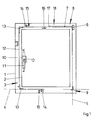
- Figure 1 shows schematically a window with a against a Frame 1 hinged wing 2 and with a Espagnolette fitting 3.
- the wing 2 can be wrapped around a tilt horizontal axis 4 with respect to frame 1 and vice versa to turn a vertical axis 5.
- the espagnolette fitting 3 has a Edge gear 10 and a handle 11 for driving a Drive rod 12.
- the handle 11 can be drawn from the Closed position Z via a rotational position D in pivot a tilted position K.
- the drive rod 12 is about several Eckumlenk Institute 13 to guided the wing 2 and carries locking pin 14, which in the illustrated closed position in strike plates 15th of the frame 1 penetrate.
- the drive rod 12 with a transmission gear 16 connected which via a sliding part 17th is connected to a Zwangsausstellvorraum 18.
- the Forced display device 18 tilts the wing 2 automatically away from the frame 1 when the espagnolette fitting 3 is moved to the tilted position.
- the transmission gearbox 16 increases the travel of the sliding part 17 at predetermined travel of the drive rod 12th
- the forced release device 18 is exemplary of a any assembly shown that has a larger Travel to the drive needed when the drive rod 12th performs.
- Figure 2 shows a greatly enlarged sectional view through the window in the region of the transmission gear 16th with adjacent components of the forced release device 18.
- the transmission gear 16 has one on a counterpart 19 rolling pinion 20.
- a bearing axis 21 of the Pinion 20 is connected to the drive rod 12.
- On the counterpart 19 opposite side is the pinion 20 with the sliding part 17 in engagement.
- the pinion 20 has an outer toothing 22, while the counterpart 19th and the sliding part 17 has a longitudinal toothing 23, 24.
- the sliding part 17 is below a fixed one Cuff rail 25 of the espagnolette fitting 3 out.
- In a drive of the drive rod 12 is the Sliding part 17 by twice the travel of the drive rod 12 postponed.
- the sliding part 17 holds a cuff rail 25 in Area of a slot penetrating control pin 26, which penetrates into a control plate 27 shown in Figure 3.
- the control plate 27 has a slot 28 for guidance the control pin 26 between the closed position and the rotational position of the espagnolette fitting 3.
- a second control pin 29 is mounted on the control plate 27 and penetrates into the stay arm 7 of the scissors 8 obliquely arranged slot 30 a.
- the espagnolette fitting 3 between the Closed position and the rotational position slides on the Sliding part 17 fastened control pin 26 in the slot 28 of the control plate 27 without moving it.
- the espagnolette fitting 3 between the rotational position and the tilting position of the wing 2 is first unlocked. Then it glides on the control panel 27 arranged control pin 29 in the slot 30 of the Ausstellarms 7 and pivots this.
- the Wing 2 tilted relative to the frame 1.
Landscapes
- Engineering & Computer Science (AREA)
- Mechanical Engineering (AREA)
- Window Of Vehicle (AREA)
- Specific Sealing Or Ventilating Devices For Doors And Windows (AREA)
- Power-Operated Mechanisms For Wings (AREA)
- Polysaccharides And Polysaccharide Derivatives (AREA)
- Transmission Devices (AREA)
- Lock And Its Accessories (AREA)
Abstract
Description
- Fig. 1
- schematisch ein Fenster mit einem erfindungsgemäßen Treibstangenbeschlag mit einer Ausstellschere,
- Fig. 2
- eine stark vergrößerte Schnittdarstellung eines Übersetzungsgetriebes des Treibstangenbeschlages mit angrenzenden Bereichen der Ausstellschere.
- Fig. 3
- eine Schnittdarstellung durch einen Teilbereich der Ausstellschere aus Figur 2 entlang der Linie III - III.
Claims (5)
- Treibstangenbeschlag zur Verriegelung eines Flügels in einem Rahmen eines Fensters, einer Fenstertür oder dergleichen mit einer längsverschieblich geführten Treibstange, mit einem Kantengetriebe zum Antrieb der Treibstange und mit einer von der Bewegung der Treibstange angetriebenen Baugruppe, dadurch gekennzeichnet, dass ein Schiebeteil (17) zum Antrieb der Baugruppe vorgesehen ist und dass zwischen dem Schiebeteil (17) und der Treibstange (12) ein Übersetzungsgetriebe (16) angeordnet ist.
- Treibstangenbeschlag nach Anspruch 1, dadurch gekennzeichnet, dass das Schiebeteil (17) mit einem Ritzel (20) in Eingriff steht, dass die Treibstange (12) mit einer Lagerachse (21) des Ritzels (20) verbunden ist und dass auf der dem Schiebeteil (17) abgewandten Seite ein feststehendes Gegenstück (19) angeordnet ist.
- Treibstangenbeschlag nach Anspruch 1 oder 2, dadurch gekennzeichnet, dass das Schiebeteil (17) flach an einer Stulpschiene (25) anliegt.
- Treibstangenbeschlag nach zumindest einem der vorhergehenden Ansprüche, dadurch gekennzeichnet, dass das Gegenstück (19) mit der Stulpschiene (25) verbunden ist.
- Treibstangenbeschlag nach zumindest einem der vorhergehenden Ansprüche, dadurch gekennzeichnet, dass das Schiebeteil (17) und das Gegenstück (19) jeweils eine Längsverzahnung (23, 24) für das Ritzel (20) aufweisen.
Applications Claiming Priority (2)
| Application Number | Priority Date | Filing Date | Title |
|---|---|---|---|
| DE10354184A DE10354184A1 (de) | 2003-11-20 | 2003-11-20 | Treibstangenbeschlag |
| DE10354184 | 2003-11-20 |
Publications (2)
| Publication Number | Publication Date |
|---|---|
| EP1533454A1 true EP1533454A1 (de) | 2005-05-25 |
| EP1533454B1 EP1533454B1 (de) | 2009-04-01 |
Family
ID=34428818
Family Applications (1)
| Application Number | Title | Priority Date | Filing Date |
|---|---|---|---|
| EP04105009A Expired - Lifetime EP1533454B1 (de) | 2003-11-20 | 2004-10-13 | Treibstangenbeschlag |
Country Status (3)
| Country | Link |
|---|---|
| EP (1) | EP1533454B1 (de) |
| AT (1) | ATE427402T1 (de) |
| DE (2) | DE10354184A1 (de) |
Cited By (1)
| Publication number | Priority date | Publication date | Assignee | Title |
|---|---|---|---|---|
| EP2392753A1 (de) * | 2010-06-02 | 2011-12-07 | Roto Frank Ag | Fenster oder dergleichen mit einem Beschlag, Beschlag, Verfahren zum Offenfeststellen eines Fensters oder dergleichen sowie Anwendung des Verfahrens bei einem Fenster oder dergleichen |
Citations (4)
| Publication number | Priority date | Publication date | Assignee | Title |
|---|---|---|---|---|
| EP0681077A2 (de) * | 1994-05-06 | 1995-11-08 | SURELOCK McGILL LIMITED | Verriegelungsvorrichtung |
| US6266981B1 (en) | 1997-11-05 | 2001-07-31 | Gretsch-Unitas Gmbh | Lock, in particular mortise lock for an exterior door |
| GB2362424A (en) * | 2000-05-17 | 2001-11-21 | Giovanni Maria Laporta | Window lock |
| US20020180218A1 (en) * | 2001-05-30 | 2002-12-05 | Timothy E. Erik | Fenestration locking system |
Family Cites Families (5)
| Publication number | Priority date | Publication date | Assignee | Title |
|---|---|---|---|---|
| DE2557303C2 (de) * | 1975-12-19 | 1978-03-23 | Siegenia-Frank Kg, 5900 Siegen- Kaan-Marienborn | Schubrichtungs-Umkehrgetriebe für Treibstangenbeschläge |
| DE3221110A1 (de) * | 1982-06-04 | 1983-12-08 | Gretsch-Unitas GmbH Baubeschläge, 7257 Ditzingen | Beschlag fuer einen kipp- und nachfolgend mindestens parallelabstellbaren fluegel eines fensters, einer tuer od. dgl. |
| DE3540346C1 (de) * | 1985-11-14 | 1987-06-19 | Fuhr Carl Gmbh & Co | In Form eines Fensters,Tuere oder dergleichen ausgebildeter Schiebefluegel |
| DE20002397U1 (de) * | 2000-02-09 | 2001-06-13 | Siegenia-Frank Kg, 57074 Siegen | Zwischengetriebe für Fenster- oder Türbeschläge |
| DE10310085B4 (de) * | 2003-03-06 | 2005-12-15 | Carl Fuhr Gmbh & Co. Kg | Schließanlage, insbesondere Türverschluss, Fensterverschluß und dergleichen |
-
2003
- 2003-11-20 DE DE10354184A patent/DE10354184A1/de not_active Withdrawn
-
2004
- 2004-10-13 DE DE502004009262T patent/DE502004009262D1/de not_active Expired - Lifetime
- 2004-10-13 EP EP04105009A patent/EP1533454B1/de not_active Expired - Lifetime
- 2004-10-13 AT AT04105009T patent/ATE427402T1/de active
Patent Citations (4)
| Publication number | Priority date | Publication date | Assignee | Title |
|---|---|---|---|---|
| EP0681077A2 (de) * | 1994-05-06 | 1995-11-08 | SURELOCK McGILL LIMITED | Verriegelungsvorrichtung |
| US6266981B1 (en) | 1997-11-05 | 2001-07-31 | Gretsch-Unitas Gmbh | Lock, in particular mortise lock for an exterior door |
| GB2362424A (en) * | 2000-05-17 | 2001-11-21 | Giovanni Maria Laporta | Window lock |
| US20020180218A1 (en) * | 2001-05-30 | 2002-12-05 | Timothy E. Erik | Fenestration locking system |
Cited By (1)
| Publication number | Priority date | Publication date | Assignee | Title |
|---|---|---|---|---|
| EP2392753A1 (de) * | 2010-06-02 | 2011-12-07 | Roto Frank Ag | Fenster oder dergleichen mit einem Beschlag, Beschlag, Verfahren zum Offenfeststellen eines Fensters oder dergleichen sowie Anwendung des Verfahrens bei einem Fenster oder dergleichen |
Also Published As
| Publication number | Publication date |
|---|---|
| DE502004009262D1 (de) | 2009-05-14 |
| DE10354184A1 (de) | 2005-06-23 |
| EP1533454B1 (de) | 2009-04-01 |
| ATE427402T1 (de) | 2009-04-15 |
Similar Documents
| Publication | Publication Date | Title |
|---|---|---|
| EP1298272B1 (de) | Laufwagenanordnung eines Beschlags für Hebe-Schiebe-Türen oder -Fenster | |
| EP0492341B1 (de) | Verschlussgetriebe für ein zweiflügeliges Fenster, od. dgl. | |
| DE10134249A1 (de) | Verriegelungsbeschlag mit drehbarer Riegelleiste | |
| EP1507059B1 (de) | Hebeschiebebeschlag | |
| EP0027261B1 (de) | Kipp-Schiebebeschlag für Fenster und Türen oder dgl. | |
| EP1176279B1 (de) | Sektionaltor | |
| EP1288418B1 (de) | Beschlagseinheit für ein Kipp- oder Drehkippfenster | |
| EP4095339B1 (de) | Stulphebelgetriebe | |
| EP1533454B1 (de) | Treibstangenbeschlag | |
| EP1076147A2 (de) | Ausstellvorrichtung für einen an einem Rahmen schwenkbar angeordneten Kipp- oder Dreh-Kipp-Flügel und Dreh-Kipp-Flügel mit einer Ausstellvorrichtung | |
| DE202011000675U1 (de) | Schrank, insbesondere Gasflaschenschrank | |
| EP1533453A1 (de) | Kantengetriebe | |
| DE202008010055U1 (de) | Gebäudeabschluss in sprengwirkungshemmender und/oder einbruchhemmender Ausführung | |
| EP1580381A2 (de) | Treibstangenbeschlag | |
| EP0784142A2 (de) | Betätigungsgetriebe für Fenster und/oder Türbeschläge mit Stell- und/oder Verriegelungsgestänge od. dgl. | |
| EP3235988A1 (de) | Fenstersystem und/oder türsystem | |
| EP1503013A2 (de) | Fenster | |
| DE60216223T2 (de) | Motorisch betriebene Schliesseinrichtung einer Öffnung in einem Fahrzeug und zugehöriges Fahrzeug | |
| DE19909365A1 (de) | Vorrichtung zum Feststellen und Verriegeln von Türen oder Wandelementen | |
| DE102004032307A1 (de) | Kantengetriebe | |
| EP0367842A1 (de) | Handhebelgetriebe zum Aufschrauben auf den Flügelrahmen von Fenstern, Türen oder dergleichen | |
| EP1619330B1 (de) | Kantengetriebe | |
| DE9310791U1 (de) | Motorische Antriebseinrichtung für ein ein- oder mehrflügeliges Torblatt | |
| EP3128109A1 (de) | Antriebsgetriebe für einen treibstangenbeschlag | |
| DE19606006B4 (de) | Antrieb für einen Flügel eines Fensters, eine Klappe oder dergleichen |
Legal Events
| Date | Code | Title | Description |
|---|---|---|---|
| PUAI | Public reference made under article 153(3) epc to a published international application that has entered the european phase |
Free format text: ORIGINAL CODE: 0009012 |
|
| AK | Designated contracting states |
Kind code of ref document: A1 Designated state(s): AT BE BG CH CY CZ DE DK EE ES FI FR GB GR HU IE IT LI LU MC NL PL PT RO SE SI SK TR |
|
| AX | Request for extension of the european patent |
Extension state: AL HR LT LV MK |
|
| 17P | Request for examination filed |
Effective date: 20050920 |
|
| AKX | Designation fees paid |
Designated state(s): AT BE BG CH CY CZ DE DK EE ES FI FR GB GR HU IE IT LI LU MC NL PL PT RO SE SI SK TR |
|
| 17Q | First examination report despatched |
Effective date: 20080424 |
|
| GRAP | Despatch of communication of intention to grant a patent |
Free format text: ORIGINAL CODE: EPIDOSNIGR1 |
|
| GRAS | Grant fee paid |
Free format text: ORIGINAL CODE: EPIDOSNIGR3 |
|
| GRAA | (expected) grant |
Free format text: ORIGINAL CODE: 0009210 |
|
| AK | Designated contracting states |
Kind code of ref document: B1 Designated state(s): AT BE BG CH CY CZ DE DK EE ES FI FR GB GR HU IE IT LI LU MC NL PL PT RO SE SI SK TR |
|
| REG | Reference to a national code |
Ref country code: GB Ref legal event code: FG4D Free format text: NOT ENGLISH |
|
| REG | Reference to a national code |
Ref country code: CH Ref legal event code: EP |
|
| REG | Reference to a national code |
Ref country code: IE Ref legal event code: FG4D Free format text: LANGUAGE OF EP DOCUMENT: GERMAN |
|
| REF | Corresponds to: |
Ref document number: 502004009262 Country of ref document: DE Date of ref document: 20090514 Kind code of ref document: P |
|
| PG25 | Lapsed in a contracting state [announced via postgrant information from national office to epo] |
Ref country code: SI Free format text: LAPSE BECAUSE OF FAILURE TO SUBMIT A TRANSLATION OF THE DESCRIPTION OR TO PAY THE FEE WITHIN THE PRESCRIBED TIME-LIMIT Effective date: 20090401 |
|
| NLV1 | Nl: lapsed or annulled due to failure to fulfill the requirements of art. 29p and 29m of the patents act | ||
| REG | Reference to a national code |
Ref country code: IE Ref legal event code: FD4D |
|
| PG25 | Lapsed in a contracting state [announced via postgrant information from national office to epo] |
Ref country code: ES Free format text: LAPSE BECAUSE OF FAILURE TO SUBMIT A TRANSLATION OF THE DESCRIPTION OR TO PAY THE FEE WITHIN THE PRESCRIBED TIME-LIMIT Effective date: 20090712 Ref country code: FI Free format text: LAPSE BECAUSE OF FAILURE TO SUBMIT A TRANSLATION OF THE DESCRIPTION OR TO PAY THE FEE WITHIN THE PRESCRIBED TIME-LIMIT Effective date: 20090401 Ref country code: PT Free format text: LAPSE BECAUSE OF FAILURE TO SUBMIT A TRANSLATION OF THE DESCRIPTION OR TO PAY THE FEE WITHIN THE PRESCRIBED TIME-LIMIT Effective date: 20090902 Ref country code: EE Free format text: LAPSE BECAUSE OF FAILURE TO SUBMIT A TRANSLATION OF THE DESCRIPTION OR TO PAY THE FEE WITHIN THE PRESCRIBED TIME-LIMIT Effective date: 20090401 |
|
| PG25 | Lapsed in a contracting state [announced via postgrant information from national office to epo] |
Ref country code: NL Free format text: LAPSE BECAUSE OF FAILURE TO SUBMIT A TRANSLATION OF THE DESCRIPTION OR TO PAY THE FEE WITHIN THE PRESCRIBED TIME-LIMIT Effective date: 20090401 Ref country code: PL Free format text: LAPSE BECAUSE OF FAILURE TO SUBMIT A TRANSLATION OF THE DESCRIPTION OR TO PAY THE FEE WITHIN THE PRESCRIBED TIME-LIMIT Effective date: 20090401 Ref country code: SE Free format text: LAPSE BECAUSE OF FAILURE TO SUBMIT A TRANSLATION OF THE DESCRIPTION OR TO PAY THE FEE WITHIN THE PRESCRIBED TIME-LIMIT Effective date: 20090701 |
|
| PG25 | Lapsed in a contracting state [announced via postgrant information from national office to epo] |
Ref country code: RO Free format text: LAPSE BECAUSE OF FAILURE TO SUBMIT A TRANSLATION OF THE DESCRIPTION OR TO PAY THE FEE WITHIN THE PRESCRIBED TIME-LIMIT Effective date: 20090401 Ref country code: IE Free format text: LAPSE BECAUSE OF FAILURE TO SUBMIT A TRANSLATION OF THE DESCRIPTION OR TO PAY THE FEE WITHIN THE PRESCRIBED TIME-LIMIT Effective date: 20090401 Ref country code: CZ Free format text: LAPSE BECAUSE OF FAILURE TO SUBMIT A TRANSLATION OF THE DESCRIPTION OR TO PAY THE FEE WITHIN THE PRESCRIBED TIME-LIMIT Effective date: 20090401 Ref country code: DK Free format text: LAPSE BECAUSE OF FAILURE TO SUBMIT A TRANSLATION OF THE DESCRIPTION OR TO PAY THE FEE WITHIN THE PRESCRIBED TIME-LIMIT Effective date: 20090401 |
|
| PLBE | No opposition filed within time limit |
Free format text: ORIGINAL CODE: 0009261 |
|
| STAA | Information on the status of an ep patent application or granted ep patent |
Free format text: STATUS: NO OPPOSITION FILED WITHIN TIME LIMIT |
|
| PG25 | Lapsed in a contracting state [announced via postgrant information from national office to epo] |
Ref country code: SK Free format text: LAPSE BECAUSE OF FAILURE TO SUBMIT A TRANSLATION OF THE DESCRIPTION OR TO PAY THE FEE WITHIN THE PRESCRIBED TIME-LIMIT Effective date: 20090401 |
|
| 26N | No opposition filed |
Effective date: 20100105 |
|
| PG25 | Lapsed in a contracting state [announced via postgrant information from national office to epo] |
Ref country code: BG Free format text: LAPSE BECAUSE OF FAILURE TO SUBMIT A TRANSLATION OF THE DESCRIPTION OR TO PAY THE FEE WITHIN THE PRESCRIBED TIME-LIMIT Effective date: 20090701 |
|
| BERE | Be: lapsed |
Owner name: AUG. WINKHAUS G.M.B.H. & CO. KG Effective date: 20091031 |
|
| PG25 | Lapsed in a contracting state [announced via postgrant information from national office to epo] |
Ref country code: MC Free format text: LAPSE BECAUSE OF NON-PAYMENT OF DUE FEES Effective date: 20091031 |
|
| REG | Reference to a national code |
Ref country code: CH Ref legal event code: PL |
|
| PG25 | Lapsed in a contracting state [announced via postgrant information from national office to epo] |
Ref country code: BE Free format text: LAPSE BECAUSE OF NON-PAYMENT OF DUE FEES Effective date: 20091031 Ref country code: LI Free format text: LAPSE BECAUSE OF NON-PAYMENT OF DUE FEES Effective date: 20091031 Ref country code: CH Free format text: LAPSE BECAUSE OF NON-PAYMENT OF DUE FEES Effective date: 20091031 Ref country code: GR Free format text: LAPSE BECAUSE OF FAILURE TO SUBMIT A TRANSLATION OF THE DESCRIPTION OR TO PAY THE FEE WITHIN THE PRESCRIBED TIME-LIMIT Effective date: 20090702 |
|
| PG25 | Lapsed in a contracting state [announced via postgrant information from national office to epo] |
Ref country code: GB Free format text: LAPSE BECAUSE OF NON-PAYMENT OF DUE FEES Effective date: 20091013 |
|
| PGFP | Annual fee paid to national office [announced via postgrant information from national office to epo] |
Ref country code: AT Payment date: 20101026 Year of fee payment: 7 |
|
| PG25 | Lapsed in a contracting state [announced via postgrant information from national office to epo] |
Ref country code: IT Free format text: LAPSE BECAUSE OF FAILURE TO SUBMIT A TRANSLATION OF THE DESCRIPTION OR TO PAY THE FEE WITHIN THE PRESCRIBED TIME-LIMIT Effective date: 20090401 |
|
| PG25 | Lapsed in a contracting state [announced via postgrant information from national office to epo] |
Ref country code: LU Free format text: LAPSE BECAUSE OF NON-PAYMENT OF DUE FEES Effective date: 20091013 |
|
| PG25 | Lapsed in a contracting state [announced via postgrant information from national office to epo] |
Ref country code: HU Free format text: LAPSE BECAUSE OF FAILURE TO SUBMIT A TRANSLATION OF THE DESCRIPTION OR TO PAY THE FEE WITHIN THE PRESCRIBED TIME-LIMIT Effective date: 20091002 |
|
| PG25 | Lapsed in a contracting state [announced via postgrant information from national office to epo] |
Ref country code: TR Free format text: LAPSE BECAUSE OF FAILURE TO SUBMIT A TRANSLATION OF THE DESCRIPTION OR TO PAY THE FEE WITHIN THE PRESCRIBED TIME-LIMIT Effective date: 20090401 |
|
| PG25 | Lapsed in a contracting state [announced via postgrant information from national office to epo] |
Ref country code: CY Free format text: LAPSE BECAUSE OF FAILURE TO SUBMIT A TRANSLATION OF THE DESCRIPTION OR TO PAY THE FEE WITHIN THE PRESCRIBED TIME-LIMIT Effective date: 20090401 |
|
| PGFP | Annual fee paid to national office [announced via postgrant information from national office to epo] |
Ref country code: FR Payment date: 20111026 Year of fee payment: 8 |
|
| REG | Reference to a national code |
Ref country code: AT Ref legal event code: MM01 Ref document number: 427402 Country of ref document: AT Kind code of ref document: T Effective date: 20121013 |
|
| REG | Reference to a national code |
Ref country code: FR Ref legal event code: ST Effective date: 20130628 |
|
| PG25 | Lapsed in a contracting state [announced via postgrant information from national office to epo] |
Ref country code: AT Free format text: LAPSE BECAUSE OF NON-PAYMENT OF DUE FEES Effective date: 20121013 |
|
| PG25 | Lapsed in a contracting state [announced via postgrant information from national office to epo] |
Ref country code: FR Free format text: LAPSE BECAUSE OF NON-PAYMENT OF DUE FEES Effective date: 20121031 |
|
| PGFP | Annual fee paid to national office [announced via postgrant information from national office to epo] |
Ref country code: DE Payment date: 20201228 Year of fee payment: 17 |
|
| REG | Reference to a national code |
Ref country code: DE Ref legal event code: R119 Ref document number: 502004009262 Country of ref document: DE |
|
| PG25 | Lapsed in a contracting state [announced via postgrant information from national office to epo] |
Ref country code: DE Free format text: LAPSE BECAUSE OF NON-PAYMENT OF DUE FEES Effective date: 20220503 |