EP1533211A2 - Lenkvorrichtung für ein Flurförderzeug - Google Patents
Lenkvorrichtung für ein Flurförderzeug Download PDFInfo
- Publication number
- EP1533211A2 EP1533211A2 EP04025710A EP04025710A EP1533211A2 EP 1533211 A2 EP1533211 A2 EP 1533211A2 EP 04025710 A EP04025710 A EP 04025710A EP 04025710 A EP04025710 A EP 04025710A EP 1533211 A2 EP1533211 A2 EP 1533211A2
- Authority
- EP
- European Patent Office
- Prior art keywords
- steering
- freewheel
- brake
- rotation
- steering member
- Prior art date
- Legal status (The legal status is an assumption and is not a legal conclusion. Google has not performed a legal analysis and makes no representation as to the accuracy of the status listed.)
- Granted
Links
- 230000008901 benefit Effects 0.000 description 2
- 230000001419 dependent effect Effects 0.000 description 1
- 210000000056 organ Anatomy 0.000 description 1
Images

Classifications
-
- B—PERFORMING OPERATIONS; TRANSPORTING
- B62—LAND VEHICLES FOR TRAVELLING OTHERWISE THAN ON RAILS
- B62D—MOTOR VEHICLES; TRAILERS
- B62D5/00—Power-assisted or power-driven steering
- B62D5/001—Mechanical components or aspects of steer-by-wire systems, not otherwise provided for in this maingroup
- B62D5/005—Mechanical components or aspects of steer-by-wire systems, not otherwise provided for in this maingroup means for generating torque on steering wheel or input member, e.g. feedback
- B62D5/006—Mechanical components or aspects of steer-by-wire systems, not otherwise provided for in this maingroup means for generating torque on steering wheel or input member, e.g. feedback power actuated
-
- B—PERFORMING OPERATIONS; TRANSPORTING
- B62—LAND VEHICLES FOR TRAVELLING OTHERWISE THAN ON RAILS
- B62D—MOTOR VEHICLES; TRAILERS
- B62D5/00—Power-assisted or power-driven steering
- B62D5/001—Mechanical components or aspects of steer-by-wire systems, not otherwise provided for in this maingroup
- B62D5/005—Mechanical components or aspects of steer-by-wire systems, not otherwise provided for in this maingroup means for generating torque on steering wheel or input member, e.g. feedback
-
- B—PERFORMING OPERATIONS; TRANSPORTING
- B62—LAND VEHICLES FOR TRAVELLING OTHERWISE THAN ON RAILS
- B62D—MOTOR VEHICLES; TRAILERS
- B62D5/00—Power-assisted or power-driven steering
- B62D5/04—Power-assisted or power-driven steering electrical, e.g. using an electric servo-motor connected to, or forming part of, the steering gear
- B62D5/0457—Power-assisted or power-driven steering electrical, e.g. using an electric servo-motor connected to, or forming part of, the steering gear characterised by control features of the drive means as such
- B62D5/046—Controlling the motor
- B62D5/0469—End-of-stroke control
-
- B—PERFORMING OPERATIONS; TRANSPORTING
- B62—LAND VEHICLES FOR TRAVELLING OTHERWISE THAN ON RAILS
- B62D—MOTOR VEHICLES; TRAILERS
- B62D6/00—Arrangements for automatically controlling steering depending on driving conditions sensed and responded to, e.g. control circuits
-
- B—PERFORMING OPERATIONS; TRANSPORTING
- B66—HOISTING; LIFTING; HAULING
- B66F—HOISTING, LIFTING, HAULING OR PUSHING, NOT OTHERWISE PROVIDED FOR, e.g. DEVICES WHICH APPLY A LIFTING OR PUSHING FORCE DIRECTLY TO THE SURFACE OF A LOAD
- B66F9/00—Devices for lifting or lowering bulky or heavy goods for loading or unloading purposes
- B66F9/06—Devices for lifting or lowering bulky or heavy goods for loading or unloading purposes movable, with their loads, on wheels or the like, e.g. fork-lift trucks
- B66F9/075—Constructional features or details
- B66F9/07509—Braking
-
- B—PERFORMING OPERATIONS; TRANSPORTING
- B66—HOISTING; LIFTING; HAULING
- B66F—HOISTING, LIFTING, HAULING OR PUSHING, NOT OTHERWISE PROVIDED FOR, e.g. DEVICES WHICH APPLY A LIFTING OR PUSHING FORCE DIRECTLY TO THE SURFACE OF A LOAD
- B66F9/00—Devices for lifting or lowering bulky or heavy goods for loading or unloading purposes
- B66F9/06—Devices for lifting or lowering bulky or heavy goods for loading or unloading purposes movable, with their loads, on wheels or the like, e.g. fork-lift trucks
- B66F9/075—Constructional features or details
- B66F9/07568—Steering arrangements
Definitions
- the invention relates to a steering device for an industrial truck, with a rotatable mounted steering member, a steering signal transmitter for detecting the rotational position of the Steering member and a braking device for generating a on the steering member acting braking torque, as well as a steerable wheel, a steering motor for Generating a steering movement of the steerable wheel and a steering angle sensor for detecting the steering angle of the steerable wheel, wherein the steering signal transmitter, the Steering angle sensor, the steering motor and the braking device with an electric Control device are connected.
- steering wheel running steering member In such running steering devices exists between the usually as a steering wheel running steering member and the upstanding on the road steering wheel no mechanical connection.
- Angle sensor executed steering signal transmitter detects the rotational position of the steering element and generates a dependent electrical signal, which then the electrical Control device is supplied.
- This control device evaluates the electrical Signal and then controls the electric steering motor, the one Steering movement of the steerable wheel causes.
- the actual steering angle of the steerable Rads is detected by the steering angle sensor and also the control device fed.
- Such steering devices are usually called electrical Designated steering devices or "steer-by-wire" steering devices.
- the forces acting on the steerable steering forces are in generic Steering devices due to the lack of mechanical connection not on transmit the steering element.
- Another useful feature of mechanical steering is that that further rotation of the steering member is no longer possible when the steered Wheels have reached their maximum steering angle.
- the invention is therefore based on the object, a steering device of the above to provide the above-mentioned type, in reaching the maximum Steering angle is noticeable in a comparable manner on the steering element, as in a mechanical steering.
- the braking device is designed such that it at least temporarily exclusively for one direction of rotation the steering member is effective and not for the other direction of rotation of the steering member is effective.
- the control device detects by a corresponding signal of the Lenkwinkelsensors that the steerable wheel has reached its maximum steering angle.
- the braking device is activated by the control device such that a further rotation of the steering member in the direction of a further enlargement of the Steering angle counteracts a braking torque.
- Turning back the steering element in however, the opposite direction is possible without hindrance.
- the operator gives the impression as if the steering member had reached a stop, the one Further rotation of the steering member in a first direction prevents a turning back of the Steering organ but without resistance allows.
- the control device is designed such that the braking device is activated
- the steering angle sensor detects, the steering angle of the steerable wheel becomes corresponds to the maximum steering angle, wherein the braking device for the Direction of rotation of the steering element, which corresponds to an increase in the steering angle, is effective, and for the other direction of rotation of the steering member, a reduction the steering angle is not effective.
- the braking device comprises at least one braking element, which is a non-rotatable Brake housing and a rotatably mounted relative to the brake housing Has brake body, wherein by actuating the brake element a Rotational movement of the brake body can be braked.
- the brake housing is For example, rigidly attached to a frame of the truck.
- the brake body however, is directly or indirectly with the steering member or with a steering member associated steering shaft, so that a rotational movement of the steering member on the brake body can be transmitted.
- a first advantageous embodiment of the invention is a Rotary movement of the steering member by means of a shaft connection to the brake body transferable, wherein the shaft connection has a defined game.
- the named Shaft connection thus provides no rigid rotary connection between the steering element and Brake body, but has in the direction of rotation a game within which the steering member can be rotated independently of the brake body.
- the shaft connection is designed such that after a change of Direction of rotation of the steering member, the rotational movement of the steering member initially not on the brake body is transmitted.
- End stop of the steerable wheel results in the following mode of action:
- the Steering member is rotated together with the brake body in the first direction until the steerable wheel has reached its mechanical steering stop. This will be the Signaled control device, which then actuates the brake element.
- One Further rotation of the steering member in the first direction is because of the actuated Brake elements practically impossible.
- Turning back the steering member in the opposite second direction is due to the game in the shaft connection initially unhindered even when the brake element is actuated.
- This Turning back is detected by the steering signal transmitter and via the control device in implemented a steering movement of the steerable wheel. This is not more on the steering stop, so that the control device releases the brake element before the end of the game in the shaft connection is reached and the rotational movement of the Steering member is transmitted to the brake body in the second direction.
- the steering member has a driver, which in engages a recess on the brake body, wherein the recess in the circumferential direction is greater than the driver.
- the driver can for example by a cylindrical pin be formed while the recess as a in Circumferentially extending slot is executed.
- a second advantageous embodiment of the invention provides that the steering member connected by at least one freewheel with the at least one brake body is, wherein the freewheel on a movement of the steering member in a first direction of rotation the brake body transmits and the freewheel movement of the steering member in one second, opposite to the first direction of rotation not on the Brake body transmits.
- the rotational movement of the steering member in a first direction at any time transmits to the brake body, a rotational movement of the steering member in the opposite second direction, however, regardless of the brake body, ie also possible with a stationary brake body.
- the brake device comprises a further brake element whose Brake body also connected by means of another freewheel with the steering member is, wherein the further freewheel movement of the steering member in the second Direction of rotation on the brake body transmits and the further freewheel movement of the steering member in the first direction of rotation does not transfer to the brake body.
- a brake element for the left-side and the right-side end stop of the steered wheels is so each provided a brake element, each with a freewheel.
- the control device is designed such that the first brake element of the Braking device is activated when the steering angle sensor detects that the Steering angle of the steerable wheel corresponds to the maximum steering angle to the left, and the second brake element of the brake device is activated when the Steering angle sensor detects that the steering angle of the steerable wheel to the maximum Steering angle to the right corresponds.
- a third possible expedient embodiment of the invention provides that the Braking device comprises at least one switchable freewheel, which is not a rotatable freewheel housing and a rotatable relative to the freewheel housing has stored freewheel body, wherein in a first switching position of the freewheel the freewheel body is rotatable in both directions of rotation and in a second Switching position of the freewheel of the freewheel body is rotatable in a first direction of rotation and is not rotatable in a second direction of rotation.
- a switchable freewheel has two Switch positions, between which switched by means of electrical signals can be.
- the Freewheel body During normal operation of the steering device is the Freewheel body and thus the steering member in both directions freely rotatable. If the steerable wheel reaches its end position, the freewheel is switched so that a Further rotation of the steering member in the direction of a further enlargement of the Steering angle is locked, a reverse rotation of the steering member, however, unhindered is possible.
- To represent a left and a right steering wheel stop includes the Braking device another switchable freewheel, wherein in a first Switching position of the further freewheel of the freewheel body in both directions of rotation is rotatable and in a second switching position of the further freewheel of the freewheel body is rotatable in the second direction of rotation and is not rotatable in the first direction of rotation.
- this is at least one brake element of a magnetic brake educated.
- the force required for the brake force is thereby electrically means an electromagnet generated.
- the at least one brake element is formed by a spring-loaded brake, There is the added benefit of having the steering wheel out of service Truck is blocked. The steering function is then at startup of the Truck released by the spring brakes are released.
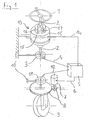
- an electric steering device of an industrial truck is shown in the the rotational movement of a running as a steering wheel steering member 1 via a steering shaft 2 is transmitted to a steering signal generator 3.
- the one on a truck-mounted Component 10 mounted steering signal generator 3 is connected via a signal line 4 with a electrical control device 5 connected via a control line 6 a electric steering motor 7 drives.
- a steering gear 8 generates the steering motor.
- 7 a steering movement of the steerable wheel 9.
- the actual steering position of the steerable wheel 9 is detected by means of a steering angle sensor 11 and a Signal line 11 also supplied to the control device.
- a braking device 13 is arranged on the steering shaft 2, which in this embodiment, a single, from the control device 5 via a Control line 14 has controllable brake element.
- the brake element comprises a non-rotatably attached to the truck-mounted component 10 Brake housing 15 and a brake body 16. When not actuated brake element the brake body 16 can be rotated freely relative to the brake housing 15 at actuated brake element, the brake body 16 is virtually torsionally rigid in the Brake housing 15 fixed.
- the brake body 16 is connected via a shaft connection having play with the steering shaft 2 connected.
- the shaft connection comprises a arranged on the steering shaft 2 pin 17, which in a recess 18 on Brake body 16 engages. Since the recess 18 is larger in the circumferential direction than that Diameter of the pin 17, the shaft connection has play.
- the operation is as follows: When the steering member 1, starting from the rotated position shown to the left (counterclockwise), the rotates Brake body 16 with, since the pin 17 on the corresponding side of the recess 18 is present. Now if the steerable wheel 9 is not shown left stop achieved, the control device 5 detects this on the basis of the corresponding Output signal of the steering sensor 11 and causes an actuation of the Bremselements, so that the brake body 16 is set and thereby also a Further rotation of the steering member 1 is prevented to the left. Turning back the Steering member 1 and the steering shaft 2 to the right, however, initially unhindered possible because of this movement due to the play in the shaft connection first is not transmitted to the brake body 16.
- Figure 2 shows an identical with respect to the operation of the steering function arrangement.
- the one at the continuous Steering shaft 2 arranged brake device 13 two brake elements, each with a Brake housing 15a, 15b and in each case a brake body 16a, 16b.
- the Brake body 16a, 16b are each by means of a freewheel 19a, 19b with the steering shaft. 2 connected, wherein the freewheel 19a at any time a rotational movement of the steering shaft 2 and so that the steering member 1 to the right (clockwise) and the freewheel 19b at any time a rotational movement of the steering shaft 2 to the left (counterclockwise) permits.
Landscapes
- Engineering & Computer Science (AREA)
- Transportation (AREA)
- Mechanical Engineering (AREA)
- Chemical & Material Sciences (AREA)
- Combustion & Propulsion (AREA)
- Structural Engineering (AREA)
- Civil Engineering (AREA)
- Life Sciences & Earth Sciences (AREA)
- Geology (AREA)
- Steering Control In Accordance With Driving Conditions (AREA)
- Non-Deflectable Wheels, Steering Of Trailers, Or Other Steering (AREA)
Abstract
Description
- Figur 1
- eine elektrische Lenkvorrichtung mit einem Bremselement und einer spielbehafteten Wellenverbindung,
- Figur 2
- eine elektrische Lenkvorrichtung mit zwei Bremselementen und zwei Freiläufen.
Claims (13)
- Lenkvorrichtung für ein Flurförderzeug, mit einem drehbar gelagerten Lenkorgan (1), einem Lenksignalgeber (3) zum Erfassen der Drehstellung des Lenkorgans (1) und einer Bremsvorrichtung (13) zum Erzeugen eines auf das Lenkorgan (1) wirkenden Bremsmoments, sowie einem lenkbaren Rad (9), einem Lenkmotor (7) zum Erzeugen einer Lenkbewegung des lenkbaren Rads (9) und einem Lenkwinkelsensor (11) zum Erfassen das Lenkwinkels des lenkbaren Rads (9), wobei der Lenksignalgeber (3), der Lenkwinkelsensor (11), der Lenkmotor (7) und die Bremsvorrichtung (13) mit einer elektrischen Steuervorrichtung (5) verbunden sind, dadurch gekennzeichnet, dass die Bremsvorrichtung (13) derart ausgeführt ist, dass sie zumindest zeitweise ausschließlich für eine Drehrichtung des Lenkorgans (1) wirksam ist und für die andere Drehrichtung des Lenkorgans (1) nicht wirksam ist.
- Lenkvorrichtung nach Anspruch 1, dadurch gekennzeichnet, dass die Steuervorrichtung (5) derart ausgeführt ist, dass die Bremsvorrichtung (13) aktiviert wird, wenn der Lenkwinkelsensor (11) erfasst, dass der Lenkwinkel des lenkbaren Rad (9) dem maximalen Lenkwinkel entspricht, wobei die Bremsvorrichtung (13) für die Drehrichtung des Lenkorgans (1), die einer Vergrößerung des Lenkwinkels entspricht, wirksam ist, und für die andere Drehrichtung des Lenkorgans (1), die einer Verringerung des Lenkwinkels entspricht, nicht wirksam ist.
- Lenkvorrichtung nach Anspruch 1 oder 2, dadurch gekennzeichnet, dass die Bremsvorrichtung (13) mindestens ein Bremselement umfasst, das ein nicht drehbares Bremsengehäuse (15, 15a, 15b) und einen relativ zu dem Bremsengehäuse (15, 15a, 15b) drehbar gelagerten Bremskörper (16, 16a, 16b) aufweist, wobei durch Betätigen des Bremselements eine Rotationsbewegung des Bremskörpers (16, 16a, 16b) abbremsbar ist.
- Lenkvorrichtung nach einem der Ansprüche 1 bis 3, dadurch gekennzeichnet, dass eine Drehbewegung des Lenkorgans (1) mittels einer Wellenverbindung auf den Bremskörper (16) übertragbar ist, wobei die Wellenverbindung ein definiertes Spiel aufweist.
- Lenkvorrichtung nach Anspruch 4, dadurch gekennzeichnet, dass die Wellenverbindung derart ausgeführt ist, dass nach einem Wechsel der Drehrichtung des Lenkorgans (1) die Drehbewegung des Lenkorgans (1) zunächst nicht auf den Bremskörper (16) übertragen wird.
- Lenkvorrichtung nach Anspruch 4 oder 5, dadurch gekennzeichnet, dass das Lenkorgan (1) einen Mitnehmer (17) aufweist, der in eine Aussparung am Bremskörper (16) eingreift, wobei die Aussparung (18) in Umfangsrichtung größer ist als der Mitnehmer (17).
- Lenkvorrichtung nach einem der Ansprüche 1 bis 3, dadurch gekennzeichnet, dass das Lenkorgan (1) mittels mindestens eines Freilaufs (19a) mit dem mindestens einen Bremskörper (16a) verbunden ist, wobei der Freilauf (19a) eine Bewegung des Lenkorgans (1) in einer ersten Drehrichtung auf den Bremskörper (16a) überträgt und der Freilauf (19a) eine Bewegung des Lenkorgans (1) in einer zweiten, zur ersten Drehrichtung entgegengesetzten Drehrichtung nicht auf den Bremskörper (16a) überträgt.
- Lenkvorrichtung nach Anspruch 7, dadurch gekennzeichnet, dass die Bremsvorrichtung (13) ein weiteres Bremselement umfasst, dessen Bremskörper (16b) ebenfalls mittels eines weiteren Freilaufs (19b) mit dem Lenkorgan (1) verbunden ist, wobei der weitere Freilauf (19b) eine Bewegung des Lenkorgans (1) in der zweiten Drehrichtung auf den Bremskörper (16b) überträgt und der weitere Freilauf (19b) eine Bewegung des Lenkorgans (1) in der ersten Drehrichtung nicht auf den Bremskörper (16b) überträgt.
- Lenkvorrichtung nach Anspruch 8, dadurch gekennzeichnet, dass die Steuervorrichtung (5) derart ausgeführt ist, dass das erste Bremselement der Bremsvorrichtung (13) aktiviert wird, wenn der Lenkwinkelsensor (11) erfasst, dass der Lenkwinkel des lenkbaren Rad (9) dem maximalen Lenkwinkel nach links entspricht, und das zweite Bremselement der Bremsvorrichtung (13) aktiviert wird, wenn der Lenkwinkelsensor (11) erfasst, dass der Lenkwinkel des lenkbaren Rads (9) dem maximalen Lenkwinkel nach rechts entspricht.
- Lenkvorrichtung nach einem der Ansprüche 1 bis 3, dadurch gekennzeichnet, dass die Bremsvorrichtung (13) mindestens einen schaltbaren Freilauf umfasst, der ein nicht drehbares Freilaufgehäuse und einen relativ zu dem Freilaufgehäuse drehbar gelagerten Freilaufkörper aufweist, wobei in einer ersten Schaltstellung des Freilaufs der Freilaufkörper in beide Drehrichtungen drehbar ist und in einer zweiten Schaltstellung des Freilaufs der Freilaufkörper in einer ersten Drehrichtung drehbar ist und in einer zweiten Drehrichtung nicht drehbar ist.
- Lenkvorrichtung nach Anspruch 10, dadurch gekennzeichnet, dass die Bremsvorrichtung (13) einen weiteren schaltbaren Freilauf umfasst, wobei in einer ersten Schaltstellung des weiteren Freilaufs der Freilaufkörper in beide Drehrichtungen drehbar ist und in einer zweiten Schaltstellung des weiteren Freilaufs der Freilaufkörper in der zweiten Drehrichtung drehbar ist und in der ersten Drehrichtung nicht drehbar ist.
- Lenkvorrichtung nach einem der Ansprüche 4 bis 9, dadurch gekennzeichnet, dass das mindestens eine Bremselement von einer Magnetbremse gebildet ist.
- Lenkvorrichtung nach einem der Ansprüche 4 bis 9, dadurch gekennzeichnet, dass das mindestens eine Bremselement von einer Federspeicherbremse gebildet ist.
Applications Claiming Priority (2)
| Application Number | Priority Date | Filing Date | Title |
|---|---|---|---|
| DE2003154410 DE10354410A1 (de) | 2003-11-21 | 2003-11-21 | Lenkvorrichtung für ein Flurförderzeug |
| DE10354410 | 2003-11-21 |
Publications (3)
| Publication Number | Publication Date |
|---|---|
| EP1533211A2 true EP1533211A2 (de) | 2005-05-25 |
| EP1533211A3 EP1533211A3 (de) | 2005-08-17 |
| EP1533211B1 EP1533211B1 (de) | 2007-10-17 |
Family
ID=34428839
Family Applications (1)
| Application Number | Title | Priority Date | Filing Date |
|---|---|---|---|
| EP04025710A Expired - Lifetime EP1533211B1 (de) | 2003-11-21 | 2004-10-29 | Lenkvorrichtung für ein Flurförderzeug |
Country Status (2)
| Country | Link |
|---|---|
| EP (1) | EP1533211B1 (de) |
| DE (2) | DE10354410A1 (de) |
Cited By (4)
| Publication number | Priority date | Publication date | Assignee | Title |
|---|---|---|---|---|
| EP1698540A1 (de) * | 2005-03-01 | 2006-09-06 | Nissan Motor Co., Ltd. | Lenksteuerungseinrichtung |
| EP1972482A2 (de) | 2007-03-20 | 2008-09-24 | Gebr. Frei GmbH & Co. KG | Lenkantriebssystem |
| EP1892173A3 (de) * | 2006-08-23 | 2008-10-29 | Jungheinrich Aktiengesellschaft | Flurförderzeug mit einer elektrischen Lenkeinrichtung sowie Verfahren zur Steuerung eines Flurförderzeugs mit einer elektrischen Lenkeinrichtung |
| EP2896558A4 (de) * | 2012-09-13 | 2016-05-11 | Nhk Spring Co Ltd | Schiffsrudervorrichtung |
Families Citing this family (3)
| Publication number | Priority date | Publication date | Assignee | Title |
|---|---|---|---|---|
| MX2008014783A (es) | 2008-02-05 | 2009-08-27 | Krueger Int Inc | Armazon para silla con soporte hueco ergonomico integral. |
| US12509337B2 (en) | 2023-04-13 | 2025-12-30 | Crown Equipment Corporation | Steering shaft assembly for a materials handling vehicle |
| DE102023134813A1 (de) * | 2023-12-12 | 2025-06-12 | REMA LIPPRANDT GmbH & Co.KG | Lenkvorrichtung eines Fahrzeugs |
Citations (1)
| Publication number | Priority date | Publication date | Assignee | Title |
|---|---|---|---|---|
| DE10033107A1 (de) | 1999-07-14 | 2001-01-18 | Linde Ag | Lenkvorrichtung für ein Fahrzeug |
Family Cites Families (4)
| Publication number | Priority date | Publication date | Assignee | Title |
|---|---|---|---|---|
| DE4122064A1 (de) * | 1990-07-03 | 1992-01-09 | Zahnradfabrik Friedrichshafen | Schaltbare kupplung |
| US6761243B2 (en) * | 2001-12-31 | 2004-07-13 | Visteon Global Technologies, Inc. | Steering control with variable damper assistance and method implementing the same |
| DE10249120A1 (de) * | 2002-10-22 | 2004-05-06 | Zf Lenksysteme Gmbh | Zahnstangen-Servolenkung für Fahrzeuge |
| US6926112B2 (en) * | 2003-10-16 | 2005-08-09 | Visteon Global Technologies, Inc. | End of travel system and method for steer by wire systems |
-
2003
- 2003-11-21 DE DE2003154410 patent/DE10354410A1/de not_active Withdrawn
-
2004
- 2004-10-29 DE DE200450005251 patent/DE502004005251D1/de not_active Expired - Lifetime
- 2004-10-29 EP EP04025710A patent/EP1533211B1/de not_active Expired - Lifetime
Patent Citations (1)
| Publication number | Priority date | Publication date | Assignee | Title |
|---|---|---|---|---|
| DE10033107A1 (de) | 1999-07-14 | 2001-01-18 | Linde Ag | Lenkvorrichtung für ein Fahrzeug |
Cited By (7)
| Publication number | Priority date | Publication date | Assignee | Title |
|---|---|---|---|---|
| EP1698540A1 (de) * | 2005-03-01 | 2006-09-06 | Nissan Motor Co., Ltd. | Lenksteuerungseinrichtung |
| US7698035B2 (en) | 2005-03-01 | 2010-04-13 | Nissan Motor Co., Ltd. | Steering control apparatus |
| EP1892173A3 (de) * | 2006-08-23 | 2008-10-29 | Jungheinrich Aktiengesellschaft | Flurförderzeug mit einer elektrischen Lenkeinrichtung sowie Verfahren zur Steuerung eines Flurförderzeugs mit einer elektrischen Lenkeinrichtung |
| EP1972482A2 (de) | 2007-03-20 | 2008-09-24 | Gebr. Frei GmbH & Co. KG | Lenkantriebssystem |
| EP1972482A3 (de) * | 2007-03-20 | 2009-09-02 | Gebr. Frei GmbH & Co. KG | Lenkantriebssystem |
| EP2896558A4 (de) * | 2012-09-13 | 2016-05-11 | Nhk Spring Co Ltd | Schiffsrudervorrichtung |
| US9389634B2 (en) | 2012-09-13 | 2016-07-12 | Nhk Spring Co., Ltd. | Helm device for boat |
Also Published As
| Publication number | Publication date |
|---|---|
| DE10354410A1 (de) | 2005-06-23 |
| DE502004005251D1 (de) | 2007-11-29 |
| EP1533211B1 (de) | 2007-10-17 |
| EP1533211A3 (de) | 2005-08-17 |
Similar Documents
| Publication | Publication Date | Title |
|---|---|---|
| DE112019002990B4 (de) | Steer-by-Wire-Lenkvorrichtung und Fahrzeug | |
| DE68909202T2 (de) | Elektrisch betätigte X-Y-Schalteinrichtung. | |
| EP1254824B1 (de) | Lenkvorrichtung für ein Kraftfahrzeug | |
| EP2117905B1 (de) | Joystick | |
| DE60033651T2 (de) | Einstelleinrichtung für den Hub einer Kraftfahrzeug-Zahnstangenlenkung | |
| DE102009017714A1 (de) | Lenkrad für ein Kraftfahrzeug mit Überlagerungslenkung | |
| DE102004027610A1 (de) | Pedaleinheit und Pedalbaugruppe für Kraftfahrzeug | |
| DE69934417T2 (de) | Vorrichtung an einem betätigungshandgriff einer feststellbremse | |
| DE102007015494A1 (de) | Lenkvorrichtung | |
| DE10126928A1 (de) | Stabilisator für ein Kraftfahrzeug | |
| EP1533211B1 (de) | Lenkvorrichtung für ein Flurförderzeug | |
| EP1358099A1 (de) | Aktuator für eine steer-by-wire-lenkanlage | |
| DE102018115650A1 (de) | Lenkradeinheit zur Erfassung einer Lenkbewegung eines Lenkrades für ein elektromechanisches Lenksystem | |
| WO2003072385A1 (de) | Fahrpedaleinheit | |
| DE3872167T2 (de) | Drosseloeffnungs-steuergeraet. | |
| DE19911892A1 (de) | Vorrichtung zur Lenkung eines Fahrzeugs | |
| DE69611705T2 (de) | Funkgesteuertes Spielzeugauto mit verbessertem Lenksystem | |
| DE102005049012B3 (de) | Antriebsrad für Kleinfahrzeug, insbesondere Rollstuhl | |
| EP1121278B1 (de) | Steuervorrichtung für zündung und lenkungsverriegelung eines kraftfahrzeugs | |
| DE102018116617A1 (de) | Lenkradeinheit mit Positionierungssystem für ein elektromechanisches Lenksystem | |
| DE3505325A1 (de) | Einrichtung zum reibungsfreien kuppeln, welche ein wahlweises abkuppeln einer abtriebswelle von einer antriebswelle erlaubt und gleichzeitig wenigstens eine bremsung der abgekuppelten abtriebswelle bewirkt, mit derartigen einrichtungen versehene motor-achsanordnung und mit einer derartigen achsanordnung versehenes einachsiges motorfahrzeug | |
| DE19918566B4 (de) | Blinkerhebelvorrichtung | |
| DE102012003303B4 (de) | Stellvorrichtung für eine Federungseinrichtung eines Kraftfahrzeugs | |
| DE102021102058A1 (de) | Pedalemulator für ein Fahrzeug | |
| EP2078126B1 (de) | Elektromechanische betätigungsvorrichtung für eine klappe oder dergleichen |
Legal Events
| Date | Code | Title | Description |
|---|---|---|---|
| PUAI | Public reference made under article 153(3) epc to a published international application that has entered the european phase |
Free format text: ORIGINAL CODE: 0009012 |
|
| AK | Designated contracting states |
Kind code of ref document: A2 Designated state(s): AT BE BG CH CY CZ DE DK EE ES FI FR GB GR HU IE IT LI LU MC NL PL PT RO SE SI SK TR |
|
| AX | Request for extension of the european patent |
Extension state: AL HR LT LV MK |
|
| PUAL | Search report despatched |
Free format text: ORIGINAL CODE: 0009013 |
|
| AK | Designated contracting states |
Kind code of ref document: A3 Designated state(s): AT BE BG CH CY CZ DE DK EE ES FI FR GB GR HU IE IT LI LU MC NL PL PT RO SE SI SK TR |
|
| AX | Request for extension of the european patent |
Extension state: AL HR LT LV MK |
|
| 17P | Request for examination filed |
Effective date: 20060124 |
|
| AKX | Designation fees paid |
Designated state(s): DE FR GB IT SE |
|
| 17Q | First examination report despatched |
Effective date: 20060407 |
|
| GRAP | Despatch of communication of intention to grant a patent |
Free format text: ORIGINAL CODE: EPIDOSNIGR1 |
|
| RIC1 | Information provided on ipc code assigned before grant |
Ipc: B62D 6/00 20060101AFI20070612BHEP |
|
| GRAS | Grant fee paid |
Free format text: ORIGINAL CODE: EPIDOSNIGR3 |
|
| GRAA | (expected) grant |
Free format text: ORIGINAL CODE: 0009210 |
|
| AK | Designated contracting states |
Kind code of ref document: B1 Designated state(s): DE FR GB IT SE |
|
| REG | Reference to a national code |
Ref country code: GB Ref legal event code: FG4D Free format text: NOT ENGLISH |
|
| REF | Corresponds to: |
Ref document number: 502004005251 Country of ref document: DE Date of ref document: 20071129 Kind code of ref document: P |
|
| REG | Reference to a national code |
Ref country code: SE Ref legal event code: TRGR |
|
| RAP2 | Party data changed (patent owner data changed or rights of a patent transferred) |
Owner name: STILL WAGNER GMBH |
|
| GBV | Gb: ep patent (uk) treated as always having been void in accordance with gb section 77(7)/1977 [no translation filed] | ||
| EN | Fr: translation not filed | ||
| PLBE | No opposition filed within time limit |
Free format text: ORIGINAL CODE: 0009261 |
|
| STAA | Information on the status of an ep patent application or granted ep patent |
Free format text: STATUS: NO OPPOSITION FILED WITHIN TIME LIMIT |
|
| 26N | No opposition filed |
Effective date: 20080718 |
|
| PG25 | Lapsed in a contracting state [announced via postgrant information from national office to epo] |
Ref country code: FR Free format text: LAPSE BECAUSE OF FAILURE TO SUBMIT A TRANSLATION OF THE DESCRIPTION OR TO PAY THE FEE WITHIN THE PRESCRIBED TIME-LIMIT Effective date: 20080801 |
|
| PG25 | Lapsed in a contracting state [announced via postgrant information from national office to epo] |
Ref country code: GB Free format text: LAPSE BECAUSE OF FAILURE TO SUBMIT A TRANSLATION OF THE DESCRIPTION OR TO PAY THE FEE WITHIN THE PRESCRIBED TIME-LIMIT Effective date: 20071017 |
|
| PG25 | Lapsed in a contracting state [announced via postgrant information from national office to epo] |
Ref country code: FR Free format text: LAPSE BECAUSE OF FAILURE TO SUBMIT A TRANSLATION OF THE DESCRIPTION OR TO PAY THE FEE WITHIN THE PRESCRIBED TIME-LIMIT Effective date: 20071031 |
|
| PGFP | Annual fee paid to national office [announced via postgrant information from national office to epo] |
Ref country code: IT Payment date: 20081025 Year of fee payment: 5 |
|
| PG25 | Lapsed in a contracting state [announced via postgrant information from national office to epo] |
Ref country code: IT Free format text: LAPSE BECAUSE OF NON-PAYMENT OF DUE FEES Effective date: 20091029 |
|
| REG | Reference to a national code |
Ref country code: DE Ref legal event code: R081 Ref document number: 502004005251 Country of ref document: DE Owner name: STILL GMBH, DE Free format text: FORMER OWNER: STILL WAGNER GMBH, 72766 REUTLINGEN, DE Effective date: 20110405 |
|
| REG | Reference to a national code |
Ref country code: DE Ref legal event code: R082 Ref document number: 502004005251 Country of ref document: DE Representative=s name: GEIRHOS & WALLER PATENT- UND RECHTSANWAELTE, DE |
|
| REG | Reference to a national code |
Ref country code: DE Ref legal event code: R082 Ref document number: 502004005251 Country of ref document: DE Representative=s name: PATENTSHIP PATENTANWALTSGESELLSCHAFT MBH, DE Effective date: 20111010 Ref country code: DE Ref legal event code: R081 Ref document number: 502004005251 Country of ref document: DE Owner name: STILL GMBH, DE Free format text: FORMER OWNER: KION WAREHOUSE SYSTEMS GMBH, 72766 REUTLINGEN, DE Effective date: 20111010 Ref country code: DE Ref legal event code: R082 Ref document number: 502004005251 Country of ref document: DE Representative=s name: GEIRHOS & WALLER PATENT- UND RECHTSANWAELTE, DE Effective date: 20111010 |
|
| REG | Reference to a national code |
Ref country code: DE Ref legal event code: R082 Ref document number: 502004005251 Country of ref document: DE Representative=s name: PATENTSHIP PATENTANWALTSGESELLSCHAFT MBH, DE |
|
| REG | Reference to a national code |
Ref country code: DE Ref legal event code: R082 Ref document number: 502004005251 Country of ref document: DE Representative=s name: PATENTSHIP PATENTANWALTSGESELLSCHAFT MBH, DE |
|
| PGFP | Annual fee paid to national office [announced via postgrant information from national office to epo] |
Ref country code: SE Payment date: 20221020 Year of fee payment: 19 Ref country code: DE Payment date: 20221020 Year of fee payment: 19 |
|
| REG | Reference to a national code |
Ref country code: DE Ref legal event code: R119 Ref document number: 502004005251 Country of ref document: DE |
|
| REG | Reference to a national code |
Ref country code: SE Ref legal event code: EUG |
|
| PG25 | Lapsed in a contracting state [announced via postgrant information from national office to epo] |
Ref country code: DE Free format text: LAPSE BECAUSE OF NON-PAYMENT OF DUE FEES Effective date: 20240501 |
|
| PG25 | Lapsed in a contracting state [announced via postgrant information from national office to epo] |
Ref country code: SE Free format text: LAPSE BECAUSE OF NON-PAYMENT OF DUE FEES Effective date: 20231030 |