EP1532806B1 - Bildverarbeitungsvorrichtung und verfahren - Google Patents
Bildverarbeitungsvorrichtung und verfahren Download PDFInfo
- Publication number
- EP1532806B1 EP1532806B1 EP03797533.1A EP03797533A EP1532806B1 EP 1532806 B1 EP1532806 B1 EP 1532806B1 EP 03797533 A EP03797533 A EP 03797533A EP 1532806 B1 EP1532806 B1 EP 1532806B1
- Authority
- EP
- European Patent Office
- Prior art keywords
- color
- image
- image data
- conversion
- gamut
- Prior art date
- Legal status (The legal status is an assumption and is not a legal conclusion. Google has not performed a legal analysis and makes no representation as to the accuracy of the status listed.)
- Expired - Lifetime
Links
Images












Classifications
-
- H—ELECTRICITY
- H04—ELECTRIC COMMUNICATION TECHNIQUE
- H04N—PICTORIAL COMMUNICATION, e.g. TELEVISION
- H04N1/00—Scanning, transmission or reproduction of documents or the like, e.g. facsimile transmission; Details thereof
- H04N1/46—Colour picture communication systems
- H04N1/56—Processing of colour picture signals
- H04N1/60—Colour correction or control
-
- H—ELECTRICITY
- H04—ELECTRIC COMMUNICATION TECHNIQUE
- H04N—PICTORIAL COMMUNICATION, e.g. TELEVISION
- H04N1/00—Scanning, transmission or reproduction of documents or the like, e.g. facsimile transmission; Details thereof
- H04N1/46—Colour picture communication systems
- H04N1/56—Processing of colour picture signals
- H04N1/60—Colour correction or control
- H04N1/6058—Reduction of colour to a range of reproducible colours, e.g. to ink- reproducible colour gamut
-
- G—PHYSICS
- G06—COMPUTING OR CALCULATING; COUNTING
- G06T—IMAGE DATA PROCESSING OR GENERATION, IN GENERAL
- G06T1/00—General purpose image data processing
-
- H—ELECTRICITY
- H04—ELECTRIC COMMUNICATION TECHNIQUE
- H04N—PICTORIAL COMMUNICATION, e.g. TELEVISION
- H04N1/00—Scanning, transmission or reproduction of documents or the like, e.g. facsimile transmission; Details thereof
- H04N1/46—Colour picture communication systems
Definitions
- the present invention relates to an image processing apparatus and method and, for example, to an image process for processing image data between image input/output devices.
- an image input device such as a digital camera, color scanner, or the like
- an image display device such as a CRT, LCD, or the like
- an edit process, modification process, retouching process, and the like to the image in accordance with the intended purpose
- an image output device such as a color printer or the like.
- an image sensed by a digital camera is often directly output from a color printer without being displayed on a color monitor.
- no image input device is required.
- Image input/output devices such as a digital camera, color scanner, color monitor, color printer, and the like have different color reproduction characteristics and ranges.
- a standard color space is used as a color space to exchange color signals between devices to execute a color process that places an importance on gradation (tincture), vividness, color difference, or the like in correspondence with the input/output purpose or application of an image.
- sRGB As a standard color space used to exchange color signals between devices, sRGB as a monitor color space is known.
- the gamut of the sRGB color space is narrower than that of an ink-jet printer.
- standard color spaces having broader gamuts sYCC, bg-sRGB, scRGB, and the like are known. However, these color spaces have broad gamuts beyond the human visible range (visual limit range), but do not define handling of data outside the visual limit range.
- the human visible range indicates a region in the xy chromaticity diagram, which is surrounded in a spectrum locus and a purple boundary, and indicates a color reproduction range which is a visible range of the human.
- Japanese Patent Laid-Open No. 4-186969 discloses an example wherein when a color outside the gamut of an image output device is input, color conversion that attaches an importance on color differences and converts the input color into a color which is closest to the input color (i.e., a color having a minimum color difference) within the gamut of the image output device is executed.
- the technique disclosed in this reference not only does not check whether the input color falls inside or outside the visual limit range, but also does not consider the tincture of original input data since that technique simply converts a color outside the gamut of the image output device into a color having a minimum color difference.
- Japanese Patent Laid-Open No. 2002-27275 obtains a digital image of a preservation space by adjusting the color value of an extended-gamut digital image to fall within a limited gamut, and expressing the limited-gamut digital image within a preservation color space. Then, this technique determines a residual image that indicates the difference between the extended-gamut digital image and limited-gamut digital image to associate them with the digital image of the preservation space.
- a preservation image and residual image are used to preserve a target image, and how to handle color space in an image process between color input/output devices that handle a color image with a broad gamut is not specified.
- US-B1-6,211,971 describes image data having N spectral bands being mapped into M-dimensional image data (N>M) for a monitor or printer.
- EP-A-0 675 638 discloses a standard colour space and EP-A-0 665 682 discloses a step of determining whether or not input colour data exists in a colour gamut of a device, and a step of mapping input colour data that falls outside of this gamut from outside the gamut into the colour gamut of the device.
- the present invention has been made to solve the aforementioned problems individually or together, and has as its object to appropriately handle image data outside a gamut.
- a preferred embodiment of the present invention discloses a method of processing image data as defined in claims 1 to 5.
- a second preferred embodiment of the present invention discloses an image processing apparatus for connecting image input/output devices as defined in claim 6.
- Fig. 1 is a block diagram showing the arrangement of an image processing apparatus 1 of this embodiment.
- an image input device 2 such as a digital camera, color scanner, or the like for inputting an image
- an image display device 3 such as a CRT, LCD, or the like for displaying an image
- an image output device 4 such as a color printer or the like for outputting an image
- an image input unit 5 is an interface such as a USB, IEEE1394, or the like, which inputs a color signal from the image input device 2.
- An image display unit 6 is a video interface which generates a color signal to be displayed on the image display device 3.
- An image output unit 7 is an interface such as IEEE1284, USB, IEEE1394, or the like, which outputs a color signal to the image output device 4.
- RGB space such as scRGB, which can express a value beyond the visual limit range
- digital data such as computer graphics data or the like can be generated irrespective of whether or not it falls within the visual limit range, and often exceeds the visual limit range.
- RGB space such as scRGB, which can express a value beyond the visual limit range
- image data which falls within the visual limit range undergoes a process such as an edge emphasis process, saturation-up process, or the like, which increases the saturation or lightness of pixels, the processed image data may often exceed the visual limit range.
- a color coordinate conversion unit 8 converts color signal coordinates (color space) among an input color signal, display color signal, output color signal, and processed color signal.
- a gamut inside/outside determination unit 9 determines if an input color signal indicates a color inside or outside the visual limit range.
- a color conversion unit 10 converts a color signal corresponding to a color outside the visual limit range into a color of an inframarginal portion of the visual limit range.
- a data buffer 11 is a memory such as a RAM or the like, which temporarily saves data for data processes.
- a visual limit range storage unit 12 is a nonvolatile memory such as a ROM, hard disk, or the like, which stores the visual limit range in a state wherein the Y values of XYZ values of black and white are normalized to 0 to 1, and also stores LCh values or RGB values as a three-dimensional (3D) range.
- a user interface (UI) unit 13 is an interface which allows the user to operate the image processing apparatus 1. Note that an interface window generated by the UI unit 13 is displayed on the image display device 3 via the image display unit 3. User's operations on the interface window are input to the UI unit 13 via a keyboard and pointing device (not shown).
- color coordinate conversion unit 8 gamut inside/outside determination unit 9, color conversion unit 10, and UI unit 13 are implemented by supplying a program to a CPU (not shown) of the image processing apparatus 1 although they may be implemented by hardware.
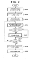
- Fig. 2 is a flow chart showing the image process of the image processing apparatus 1. This image process is executed by the CPU of the image processing apparatus 1.
- the image data When image data is input from the image input device 2 via the image input unit 5, the image data is written in the data buffer 11 (S201).
- the input image data undergoes color coordinate conversion into XYZ values by the color coordinate conversion unit 8 (S202).
- scRGB is used as color coordinate values of the input image data.
- Visual limit range information is read out from the visual limit range storage unit 12 (S203), and the gamut inside/outside determination unit 9 determines whether the image data which has undergone the color coordinate conversion falls inside or outside the visual limit range (S204). If the determination result indicates that the image data falls within the visual limit range, the flow jumps to step S207; otherwise, the flow advances to step S206 (S205).
- the color conversion unit 10 converts that image data into image data corresponding to a color of an inframarginal portion of the visual limit range, and writes the converted data at a corresponding location on the data buffer 11 (S206). It is then determined if image data to be processed corresponds to the last pixel of the input image data (S207). If the image data to be processed does not correspond to the last pixel, the flow returns to step S204.
- the color coordinate conversion unit 8 executes color coordinate conversion of the image data stored in the data buffer 11 from XYZ values into output color signal coordinate values (S208).
- scRGB is used as output color coordinate values.
- R scRGB 16 R scRGB ⁇ 8192 + 4096
- G scRGB 16 G scRGB ⁇ 8192 + 4096
- B scRGB 16 B scRGB ⁇ 8192 + 4096
- the image data stored in the data buffer 11 is output to the image display device 3 or image output device 4 via the image display unit 6 or image output unit 7 (S209), thus ending the process.
- Fig. 3 is a flow chart showing the process for reading the visual limit range information in step S203.
- the XYZ values of black as the lower limit of the visual limit range are read from the visual limit range storage unit 12, and are set in registers Xk, Yk, and Zk (S301).
- the XYZ values of white as the upper limit of the visual limit range are read, and are set in registers Xw, Yw, and Zw (S302).
- 3D information (LCh values) of the visual limit range are read (S303), thus ending the process.
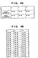
- Figs. 4A and 4B show an example of the visual limit range information stored in the visual limit range storage unit 12, and respectively show the XYZ values of black information and white information of the visual limit range ( Fig. 4A ) and the LCh values of 3D information of the visual limit range ( Fig. 4B ).
- equations (5.1) to (5.4) (using D65 as white) and equation (6) are used to calculate LCh values based on XYZ values ranging from (0.0, 0.0, 0.0) to (95.05, 100.0, 108.91) and, for example, C values corresponding to maximum saturation levels in 10-step increments of L and h values are stored.
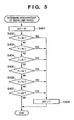
- Fig. 5 is a flow chart showing a process for determining whether a color falls inside or outside the visual limit range in step S204.
- a gamut inside/outside determination flag OUT is initialized (S401), and it is checked if an X value of image data is smaller than the lower limit value Xk of the visual limit range (S402). Likewise, it is sequentially checked if a Y value is smaller than the lower limit value Yk (S403), if a Z value is smaller than the lower limit value Zk, if the X value is larger than the upper limit value Xw of the visual limit range (S405), if the Y value is larger than the upper limit value Yw (S406), and if the Z value is larger than the upper limit value Zw (S407). If it is determined in any of these steps that the value of interest is smaller than the lower limit value or is larger than the upper limit value, the flow advances to step S408; otherwise, the process ends.
- Fig. 6 is a flow chart showing the color conversion process in step S206
- Fig. 7 shows a color conversion method setup window 601 as a user interface window used to set a color conversion method
- Fig. 8 is a graph for explaining the color conversion method.
- a user interface shown in Fig. 7 is presented to make the user set a color conversion method (S504).
- a color conversion method setup window 601 includes a basic setup window 602 used to select a basic color conversion method.
- the user wants to set the color conversion method in more detail to set a preferential conversion method in addition to the basic setup
- he or she checks a detailed setup check box 603 and selects a preferential conversion condition using radio buttons on a detailed setup window 604.
- “hue preservation” is selected as basic color conversion
- “gradation preference” is selected as the conversion condition in the example of Fig. 7 .
- the color conversion unit 10 executes color conversion in accordance with the set color conversion method (and conversion condition) (S505).
- Fig. 8 shows the color conversion executed in step S505, and shows a color conversion direction when "hue preservation" is selected as the basic color conversion method. Note that the ordinate plots lightness L, and the abscissa plots saturation C and also a visual limit range 700 read in step S303.
- an input color 701 is converted into a color on an inframarginal portion 702 of the visual limit range 700 so as not to change saturation.
- color difference preference the input color 701 is converted into a color on an inframarginal portion 703 so as to minimize the color difference;
- grade preference the input color 701 is converted into a color on an inframarginal portion 704 so as not to change gradation; or when "lightness preference” is selected, the input color 701 is converted into a color on an inframarginal portion 705 so as not to change lightness.
- the color coordinate conversion unit 8 converts the LCh values that have undergone the color conversion into Lab values using an inverse conversion equation of equation (6) (S506), converts the Lab values into XYZ values using inverse conversion equations of equations (5.1) to (5.4) (S507), and divides the XYZ values by 100 to set the original scale (S508), thus ending the process.
- the color outside the visual limit range can be converted into a color on the inframarginal portion of the visual limit range while preserving tincture or the like as much as possible.
- mapping into the visual limit range is required to convert a pixel having a color outside the visual limit range into that having a color inside the visual limit range, since image data must be finally visually observed by a person. If mapping of the first embodiment is not made, since a conversion destination within the visual limit range of a color outside the visual limit range is unknown, that color alone is converted into a different color, and connection with surrounding pixels deteriorates, thus considerably impairing the image quality. When the color conversion process of gradation-preferential hue preservation is executed like in the first embodiment, a color outside the visual limit range is processed so as not to change its tincture as much as possible. Hence, connection with surrounding pixels can be prevented from deteriorating.
- Fig. 9 is a block diagram showing the arrangement of the image processing apparatus 1 of the first example.
- An internal process gamut storage unit 14 is a nonvolatile memory such as a ROM, hard disk, or the like, which stores an internal process gamut having three, R, G, and B points as vertices. Note that the internal process gamut storage unit 14 stores the RGB values of black and white, which are normalized to 0 to 1, as will be described in detail later. Also, the unit 14 stores LCh values as a 3D range.
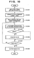
- Fig. 10 is a flow chart showing the image process of the image processing apparatus 1. This image process is executed by the CPU of the image processing apparatus 1.
- step S1202 When image data is input from the image input device 2 via the image input unit 5, the image data is written in the data buffer 11 (S1201).
- the input image data undergoes color coordinate conversion into internal process RGB values via XYZ values by the color coordinate conversion unit 8 (S1202).
- Gamut information of an internal process color signal is read out from the internal process gamut storage unit 14 (S1203), and the gamut inside/outside determination unit 9 determines whether the image data which has undergone the color coordinate conversion falls inside or outside the internal process gamut (S1204). If the determination result indicates that the image data falls within the internal process gamut, the flow jumps to step S1207; otherwise, the flow advances to step S1206 (S1205).
- the color conversion unit 10 converts that image data into image data corresponding to a color of an inframarginal portion of the internal process gamut, and writes the converted data at a corresponding location on the data buffer 11 (S1206). It is then determined if image data to be processed corresponds to the last pixel of the input image data (S1207). If the image data to be processed does not correspond to the last pixel, the flow returns to step S1204.
- the image data stored in the data buffer 11 is output to the image display device 3 or image output device 4 via the image display unit 6 or image output unit 7 (S1208), thus ending the process.
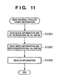
- Fig. 11 is a flow chart showing the process for reading the internal process gamut information in step S1203.
- the RGB values of black as the lower limit of the internal process gamut are read from the internal process gamut storage unit 12, and are set in registers Rk, Gk, and Bk (S1301).
- the RGB values of white as the upper limit of the internal process gamut are read, and are set in registers Rw, Gw, and Bw (S1302).
- 3D information (LCh values) of the internal process gamut are read (S1303), thus ending the process.
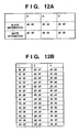
- Figs. 12A and 12B show an example of the internal process gamut information stored in the internal process gamut storage unit 14, and respectively show the RGB values of black information and white information of the internal process gamut ( Fig. 12A ) and the LCh values of 3D information of the internal process gamut ( Fig. 12B ).
- equations (5.1) to (5.4) using D65 as white) and equation (6) are used to calculate LCh values based on those XYZ values and, for example, C values corresponding to maximum saturation levels in 10-step increments of L and h values are stored.
- Fig. 13 is a flow chart showing the process for determining whether a color falls inside or outside an internal process gamut in step S1204.
- a gamut inside/outside determination flag OUT is initialized (S1401), and it is checked if an R value of image data is smaller than the lower limit value Rk of the internal process gamut (S1402). Likewise, it is sequentially checked if a G value is smaller than the lower limit value Gk (S1403), if a B value is smaller than the lower limit value Bk, if the R value is larger than the upper limit value Rw of the internal process gamut (S1405), if the G value is larger than the upper limit value Gw (S1406), and if the B value is larger than the upper limit value Bw (S1407). If it is determined in any of these steps that the value of interest is smaller than the lower limit value or is larger than the upper limit value, the flow advances to step S1408; otherwise, the process ends.
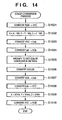
- Fig. 14 is a flow chart showing the color conversion process in step S1206.
- the color coordinate conversion unit 8 converts the Lab values into LCh values using equation (6) (S1504), and the user interface shown in Fig. 7 is presented to make the user set a color conversion method (S1505). Then, the color conversion unit 10 executes color conversion in accordance with the set color conversion method (S1506).
- the color coordinate conversion unit 8 converts the LCh values that have undergone the color conversion into Lab values using an inverse conversion equation of equation (6) (S1507), converts the Lab values into XYZ values using inverse conversion equations of equations (5.1) to (5.4) (S1508), and divides the XYZ values by 100 to set the original scale (S1509).
- the color coordinate conversion unit 8 converts the XYZ values into RGB values of the internal process color signal using equation (7), thus ending the process.
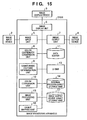
- Fig. 15 is a block diagram showing the arrangement of the image processing apparatus 1 of the second example.
- An image processing unit 15 executes image processes such as color correction and the like.
- a gamut mapping unit 16 maps the internal process gamut to the gamut of the image output device 4.
- An image output device gamut storage unit 17 stores LCh values as a 3D range, i. e., the gamut of the image output device 4, as will be described in detail later.
- Fig. 16 is a flow chart showing the image process of the image processing apparatus 1. This image process is executed by the CPU of the image processing apparatus 1.
- step S2201 When image data is input from the image input device 2 via the image input unit 5, the image data is written in the data buffer 11 (S2201).
- the input image data undergoes color coordinate conversion into internal process RGB values via XYZ values by the color coordinate conversion unit 8 (S2202).
- scRGB is used as color coordinate values of the input image data. Therefore, color coordinate conversion in step S2202 uses equations (1), (2), and (7). Note that the converted RGB value may undergo a gamma conversion process as needed.
- gamut information of an internal process color signal is read out from the internal process gamut storage unit 14 (S2203), and the gamut inside/outside determination unit 9 determines whether the image data which has undergone the color coordinate conversion falls inside or outside the internal process gamut (S2204). If the determination result indicates that the image data falls within the internal process gamut, the flow jumps to step S2207; otherwise, the flow advances to step S2206 (S2205).
- the color conversion unit 10 converts that image data into image data corresponding to a color of an inframarginal portion of the internal process gamut, and writes the converted data at a corresponding location on the data buffer 11 (S2206). It is then determined if image data to be processed corresponds to the last pixel of the input image data (S2207). If the image data to be processed does not correspond to the last pixel, the flow returns to step S2204.
- the image processing unit 15 applies image processes such as gradation correction, color correction, and the like to the image data stored in the data buffer 11 (S2208), and the gamut mapping unit 16 maps the internal process gamut to the gamut of the image output device 4 (S2209). Then, the gamut-mapped image data is output to the image output device 4 via the image output unit 7 (S2210), thus ending the process.
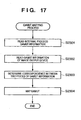
- Fig. 17 is a flow chart showing the process for mapping the internal process gamut to the gamut of the image output device in step S2209.
- This gamut information includes the LCh values of 3D information of the internal process gamut, as has been explained using Figs. 12A and 12B .
- the 3D information to be read out includes C values corresponding to maximum saturation levels in 10-step increments of L and h values.
- the RGB values of an internal process color signal corresponding to these LCh values are also stored in the internal process gamut storage unit 14, and are read in step S2301.
- the gamut information of the image output device 4 is read from the image output device gamut storage unit 17 (S2302).
- This gamut information includes L'C'h' values indicating the gamut of the image output device 4 as in the 3D information of the internal process gamut.
- the 3D information to be read out includes, for example, C' values corresponding to maximum saturation levels in 10-step increments of L' and h' values.
- the R'G'B' values of an image output color signal corresponding to these L'C'h' values are stored in the image output device gamut storage unit 17, and are read out in step S2302.
- the LCh values of the internal process gamut and the L'C'h' values of the gamut of the image output device 4 are obtained for each lightness L value and hue h value.
- the correspondence among the LCh values, L'C'h' values, RGB values, and R'G'B' values is determined to generate a 3D lookup table (3DLUT) (S2303).
- the gamut of an image to be processed is converted from the internal process gamut to the gamut of the image output device 4 (S2304), thus ending the process.
- the color conversion into the XYZ value uses conversion equations with Y which normalized to 0 to 1.
- Y may be normalized to 0 to 100.
- Fig. 7 shows the color conversion method displayed on the interface window of Fig. 7 .
- the present invention is not limited to such specific color conversion method, and any other color conversion methods of user's choice may be used.
- Fig. 8 shows the conversion direction of each color conversion method, but the present invention is not limited to such specific conversion direction.
- the color after color conversion is that on the inframarginal portion of the gamut. Alternatively, a color may be converted into a color inside the gamut.
- color coordinate system used in color conversion is not limited to the LCh coordinate system, and any other color systems may be used.
- D65 is used as white, but the present invention is not limited to this.
- the selection method using buttons has been exemplified as the user interface window shown in Fig. 7 .
- the present invention is not limited to such specific selection method, and a user interface window with which the user selects using, e. g., a drop-down menu may be adopted.
- a user interface window to which the user directly inputs keywords may be used. Furthermore, the user may select a color after color conversion on the color coordinate system. That is, the configuration of the user interface is not particularly limited as long as the user can make setups of his or her choice.
- the LCh values are stored as gamut information.
- the present invention is not limited to such specific information, and any other formats that can express a 3D gamut may be used.
- the gamut information may be stored in accordance with a given format such as an ICC profile or the like.
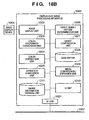
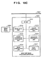
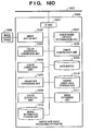
- Figs. 18A to 18D are block diagrams showing the arrangement of an image processing apparatus according to the third example.
- Reference numeral 1001 denotes an input-side image processing apparatus of the third example; 1002, a display-side image processing apparatus of the third example; 1003, an output-side image processing apparatus of the third example; 1004, an image input device such as a digital camera, color scanner, or the like, which is used to input an image; 1005, an image display device such as a CRT, LCD, or the like, which is used to display an image; and 1006, an image output device such as a color printer or the like, which is used to output an image.
- the internal arrangement of the input-side image processing apparatus 1001 will be explained first.
- Reference numeral 1011 denotes an interface (I/F) unit which is used to exchange data between the input-side image processing apparatus 1001 and other apparatuses; 1012, an image input unit for inputting image data input by the image input device 1004; 1013, a color coordinate conversion unit for performing color conversion between an image input device color space and color conversion work space, and color conversion between the color conversion work space, and a color expression space; 1014, an image compression unit for compressing the input image to reduce the data size upon exchanging the image with other apparatuses; 1015, a color correction unit for performing color correction of the input image; 1016, a gradation conversion unit for performing gradation conversion of the input image; and 1017, a data buffer for temporarily holding image data for image data processes.
- a communication line 1007 such as a system bus, a local area network (LAN), a serial bus which conforms to or based on IEEE 1394 standards or Universal Serial Bus (USB) standards, or the like.
- Reference numeral 1021 denotes an I/F unit for exchanging data between the display-side image processing apparatus 1002 and other apparatuses;
- 1022 an image display unit for displaying image data to be displayed on the image display device 1005;
- 1023 a color coordinate conversion unit for performing color conversion between an image display device color space and color conversion work space, and color conversion between the color conversion work space, and a color expression space;
- 1024 a color correction unit for performing color correction of the image;
- 1025 a gradation conversion unit for performing gradation conversion of the image;
- 1026 a gamut inside/outside determination unit for determining if a color falls inside/outside a gamut;
- 1027 a gamut compression unit for compressing the gamut;
- 1028 a data buffer for temporarily holding image data for image data processes;
- 1029 an image compression/expansion unit for compressing/expanding an image to reduce the data size upon exchanging the image with other apparatuses;
- Reference numeral 1031 denotes an I/F unit for exchanging data between the output-side image processing apparatus 1003 and other apparatuses; 1032, an image output unit for outputting image data to be output by the image output device 1006; 1033, a color coordinate conversion unit for performing color conversion between a color conversion work space and color expression space; 1034, a color correction unit for performing color correction of the image; 1035, a gradation conversion unit for performing gradation conversion of the image; 1036, a color separation unit; 1037, a gamut inside/outside determination unit for determining if a color falls inside/outside a gamut; 1038, a gamut compression unit for compressing the gamut; 1039, a data buffer for temporarily holding image data for image data processes; 1310, an output gamut data storage unit for storing gamut information of the image output device 1006; 1311, an image expansion unit for expanding an image input from another apparatus; and 1312, a range
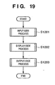
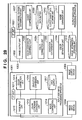
- Fig. 19 is a flow chart of image processes executed by the input-side image processing apparatus 1001, display-side image processing apparatus 1002, and output-side image processing apparatus 1003.
- the color conversion processes executed in the input-side image processing apparatus 1001, display-side image processing apparatus 1002, and output-side image processing apparatus 1003 will be described in detail below using the flow chart of Fig. 19 .
- step S1201 the input-side image processing apparatus 1001 executes image processes.
- the display-side image processing apparatus 1002 executes image processes.
- the output-side image processing apparatus 1003 executes image processes, thus ending the processes.
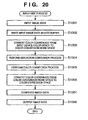
- Fig. 20 is a flow chart for explaining the image processes executed in the input-side image processing apparatus 1001 in step S1201. A detailed explanation will be given below using the flow chart of Fig. 20 .
- step S1301 the image input unit 1012 inputs an image using the image input device 1004.
- step S1302 the input image data is written in the data buffer 1017.
- step S1303 the color coordinate conversion unit 1013 performs color coordinate conversion from an input device color space RiGiBi (RGB values normalized to 0 to 1) into a color conversion work space R1G1B1 (RGB values normalized to 0 to 1) used to execute the color conversion process inside the input-side image processing apparatus 1001.
- RiGiBi RGB values normalized to 0 to 1
- R1G1B1 RGB values normalized to 0 to 1
- the color conversion work space may use R1'G1'B1' as values after gamma conversion of R1G1B1.
- step S1304 the gradation conversion unit 1016 executes gradation correction process for correcting gradation characteristics unique to the image input device 1004, and converting input image data into desired gradation characteristic data.
- step S1305 the color correction unit 1015 executes color correction processes for correcting color characteristics unique to the image input device 1004, and converting input image data into desired color characteristic data.
- step S1306 the color coordinate conversion unit 1013 performs a color coordinate conversion process from the color conversion work space R1G1B1 onto a color expression space scRGB used to exchange data with other apparatuses. Note that the color expression space scRGB can express a whole visual range. This conversion uses equations (13) to (15).
- Equation (13) is an inverse conversion equation of equation (12).
- R scRGB G scRGB B scRGB 3.2406 - 1.5372 - 0.4986 - 0.9689 1.8758 0.0415 0.0557 - 0.2040 1.0570 ⁇ X Y Z
- the color expression space scRGB (relative scene RGB color space) given by equation (14) adopts D65 as a white reference point.
- XYZ data undergo a white conversion process to D65 by:
- R scRGB 16 R scRGB ⁇ 8192 + 4096
- G scRGB 16 G scRGB ⁇ 8192 + 4096
- B scRGB 16 B scRGB ⁇ 8192 + 4096 before conversion of equation (14).
- step S1307 the image compression unit 1014 compresses the image data to reduce the transfer load upon exchanging the image with other apparatuses.
- step S1308 the I/F unit 1011 outputs the image to other apparatuses, thus ending the process.
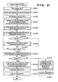
- Fig. 21 is a flow chart for explaining the image processes executed in the display-side image processing apparatus 1002 in step S1202. A detailed explanation will be given below using the flow chart of Fig. 21 .
- step S2401 the image input unit 1021 inputs an image.
- step S2402 the input image data is written in the data buffer 1028.
- step S2403 the image compression/expansion unit 1029 expands the input compressed image data.
- step S2404 the color coordinate conversion unit 1023 performs color coordinate conversion from the color expression space scRGB into a color conversion work space R1G1B1 (RGB values normalized to 0 to 1) used to execute the color conversion process in the display-side image processing apparatus 1002.
- step S2405 range information of the color conversion work space is read out from the range information storage unit 1211.
- the gamut inside/outside determination unit 1026 determines in step S2406 whether the color signal that has undergone color coordinate conversion in step S2404 falls inside or outside the color conversion work space range. It is checked in step S2407 whether or not the determination result in step S2406 indicates inside the range. If the determination result indicates inside the range, the flow jumps to step S2409; otherwise, the flow advances to step S2408.
- step S2408 the gamut compression unit 1011 compresses the color signal, which is determined in step S2406 to fall outside the color conversion work space range, to the inframarginal portion of the color conversion work space range. It is then determined in step S2409 if a pixel to be processed is the last pixel of the input image data. If the pixel to be processed is not the last pixel, the flow returns to step S2406; otherwise, the flow advances to step S2410.
- step S2410 the gradation conversion unit 1025 and color correction unit 1024 respectively execute the gradation conversion process and color correction process for converting image data into desired gradation characteristic data and desired color characteristic data. It is checked in step S2411 if the processed image data is to be displayed on the image display device 1005. If the image data is to be displayed, the flow advances to step S2415; otherwise, the flow advances to step S2412.
- step S2412 the color coordinate conversion unit 1023 executes the color coordinate conversion process from the color conversion work space R1G1B1 into the color expression space scRGB used to exchange data with other apparatuses.
- This conversion uses equations (13) to (15).
- the color expression space scRGB given by equation (14) adopts D65 as a white reference point.
- the image compression/expansion unit 1029 compresses image data to reduce the transfer load upon exchanging the image with other apparatuses.
- step S2414 the I/F unit 1021 outputs the image to other apparatuses, thus ending this process.
- step S2416 the image display unit 1022 displays the image using the image display device 1005, thus ending this process.
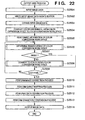
- Fig. 22 is a flow chart for explaining the image processes executed in the output-side image processing apparatus 1003 in step S1203. A detailed explanation will be given below using the flow chart of Fig. 22 .
- step S2501 the I/F unit 1031 inputs an image.
- step S2502 the input image data is written in the data buffer 1039.
- step S2503 the image expansion unit 1311 expands the input compressed image data.
- step S2504 the color coordinate conversion unit 1033 performs color coordinate conversion from the color expression space scRGB into a color conversion work space R1G1B1 (RGB values normalized to 0 to 1) used to execute the color conversion process in the output-side image processing apparatus 1003. This conversion uses equations (16) to (17), and equation (12). Note that the color conversion work space may use R1'G1'B1' as values after gamma conversion of R1G1B1.
- step S2505 range information of the color conversion work space is read out from the range information storage unit 1312.
- the gamut inside/outside determination unit 1037 determines in step S2506 whether the color signal that has undergone color coordinate conversion in step S2504 falls inside or outside the color conversion work space range. It is checked in step S2507 whether or not the determination result in step S2506 indicates inside the range. If the determination result indicates inside the range, the flow jumps to step S2509; otherwise, the flow advances to step S2508.
- step S2508 the gamut compression unit 1038 compresses the color signal, which is determined in step S2506 to fall outside the color conversion work space range, to the inframarginal portion of the color conversion work space range. It is then determined in step S2509 if a pixel to be processed is the last pixel of the input image data. If the pixel to be processed is not the last pixel, the flow returns to step S2506; otherwise, the flow advances to step S2510.
- step S2510 the gradation conversion unit 1035 and color correction unit 1034 respectively execute the gradation conversion process and color correction process for converting image data into desired gradation characteristic data and desired color characteristic data.
- the color conversion work space R1G1B1 undergoes gamut compression to an output device color space RoGoBo.
- the gamut compression uses a conversion table stored in the output gamut data storage unit 1310. This conversion table is, e.g., a 3D LUT.
- the color separation unit 1036 separates the output device color space RoGoBo into color signals unique to the output device.
- step S2513 the gradation conversion unit 1035 executes a gradation conversion process such as halftoning or the like.
- the image output unit 1032 outputs the image using the image output device 1006, thus ending this process.
- Fig. 23 is a flow chart of the process for reading out the range information of the color conversion work space from the range information storage units 1211 and 1312 in steps S2405 and S2505. A detailed explanation will be given using the flow chart of Fig. 23 .
- step S1601 the RGB values of black as the lower limit values of the color conversion work space are read from the range information storage unit 1211 (1312) and are set in Rk, Gk, and Bk.
- step S1602 the RGB values of white as the upper limit values of the color conversion work space are read from the range information storage unit 1211 (1312) and are set in Rw, Gw, and Bw.
- step S1603 3D information (LCh values) of the color conversion work space are read, thus ending the process.
- Figs. 27A and 27B show the RGB values of black information and white information of the color conversion work space and the LCh values of 3D information of the color conversion work space as an example of the color conversion work space information stored in the range information storage units 1211 and 1312.
- equation (13) As the 3D information, after XYZ values obtained by equation (13) using the RGB values ranging from (0.0, 0.0, 0.0) to (1.0, 1.0, 1.0) are multiplied by 100, equations (19.1) to (19.4) (using D65 as white) and equation (20) are used to calculate LCh values based on those XYZ values and, for example, C values corresponding to maximum saturation levels in 10-step increments of L and h values are stored. As the 3D information, for example, C values corresponding to maximum saturation levels in 10-step increments of L and h values are stored.
- Fig. 24 is a flow chart showing the process executed in the gamut inside/outside determination units 1026 and 1037 to determine in steps S2406 and S2506 whether a color signal falls inside or outside the color conversion work space range. A detailed explanation will be given using the flow chart of Fig. 24 .
- a gamut inside/outside determination flag OUT is initialized in step S1701. It is checked in step S1702 if the R value of a pixel to be processed is smaller than the lower limit value Rk of the color conversion work space. If R ⁇ Rk, the flow advances to step S1708; otherwise, the flow advances to step S1703. It is checked in step S1703 if the G value of the pixel to be processed is smaller than the lower limit value Gk of the color conversion work space. If G ⁇ Gk, the flow advances to step S1708; otherwise, the flow advances to step S1704. It is checked in step S1704 if the B value of the pixel to be processed is smaller than the lower limit value Bk of the color conversion work space.
- step S1708 If B ⁇ Bk, the flow advances to step S1708; otherwise, the flow advances to step S1705. It is checked in step S1705 if the R value of the pixel to be processed is larger than the upper limit value Rw of the color conversion work space. If R > Rw, the flow advances to step S1708; otherwise, the flow advances to step S1706. It is checked in step S1706 if the G value of the pixel to be processed is larger than the upper limit value Gw of the color conversion work space. If G > Gw, the flow advances to step S1708; otherwise, the flow advances to step S1707. It is checked in step S1707 if the B value of the pixel to be processed is larger than the upper limit value Bw of the color conversion work space. If B > Bw, the flow advances to step S1708; otherwise, the process ends. In step S1708, '1' indicating outside the gamut is set in the gamut inside/outside determination flag OUT, thus ending the process.
- Fig. 25 is a flow chart of the gamut compression executed by the gamut compression units 1027 and 1038 to convert a color signal which is determined to fall outside the color conversion work space to the inframarginal portion of the color conversion work space in steps S2408 and S2508. A detailed explanation will be given using the flow chart of Fig. 25 .
- step S1801 the R1G1B1 values of the color conversion work space color signal are converted into XYZ values using equation (13).
- step S1802 the XYZ values are respectively multiplied by 100 to adjust the scale (since the calculation results of the above equations are scaled so that Y falls within the range from 0 to 1).
- step S1803 the XYZ values are converted into Lab values using equations (19.1) to (19.4).
- step S1804 the Lab values are converted into LCh values using equation (20).
- step S1805 the user interface shown in Fig. 7 is presented to set a color conversion method.
- a basic color conversion method is set using a basic setup window 602 used to select.
- the user wants to set the color conversion method in more detail to set a preferential conversion method in addition to the basic setup
- he or she checks a detailed setup check box 603 and makes detailed setups on a detailed setup window 604.
- “hue preservation conversion” is set as basic color conversion
- “gradation preference” is set as another preferential setup in Fig. 7 .
- step S1806 color conversion is performed in accordance with the color conversion method set in step S1805.
- Fig. 26 shows the color conversion process executed in step S1806, and shows a color conversion direction when "hue preservation" is selected as the basic color conversion method. Note that the ordinate plots lightness L, and the abscissa plots saturation C and also a color conversion work space 3000 read in steps S2405 and S2505.
- saturation preference is selected on the detailed setup window 604
- an input color 3001 is converted into a color on an inframarginal portion 3002 of the color conversion work space so as not to change saturation.
- the input color 3001 is converted into a color on an inframarginal portion 3003 of the color conversion work space so as to minimize the color difference.
- the input color 3001 is converted into a color on an inframarginal portion 3004 of the color conversion work space so as not to change gradation.
- the input color 3001 is converted into a color on an inframarginal portion 3005 of the color conversion work space so as not to change lightness.
- step S1807 the LCh values are converted into Lab values using the inverse conversion equation of equation (20).
- step S1808 the Lab values are converted into XYZ values using the inverse conversion equations of equations (19.1) to (19.4).
- step S1809 the XYZ values are divided by 100 to set the original scale.
- step S1810 the XYZ values are converted into R1G1B1 values of the color conversion work space signal, thus ending the process.
- the color expression space that can express the whole visual range is used to exchange image data between the devices, and the color conversion work space that includes the gamut of the device is independently used in the color conversion process inside the device.
- the image input device, image display device, and image output device can exchange data of the visual range, and can execute color conversion suited to each individual device.
- Fig. 28 is a block diagram showing the arrangement of the input-side image processing apparatus 1001 and the output-side image processing apparatus 1003 according to the fourth example.
- this embodiment comprises only the input-side image processing apparatus 1001 and output-side image processing apparatus 1003.
- Fig. 29 is a flow chart of image processes executed by the input-side image processing apparatus 1001 and output-side image processing apparatus 1003.
- step S2301 the input-side image processing apparatus 1001 executes image processes.
- step S2302 the output-side image processing apparatus 1003 executes image processes, thus ending the processes. Note that the processing contents in step S2301 are the same as those in step S1201, and the processing contents in step S2302 are the same as those in step S1203.
- the color expression space that can express the whole visual range is used to exchange image data between the devices, and the color conversion work space that includes the gamut of the device is independently used in the color conversion process inside the device.
- the image input device and image output device can exchange data of the visual range, and can execute color conversion suited to each individual device.
- Figs. 30A to 30D are block diagrams showing the arrangement of the input-side image processing apparatus 1001, display-side image processing apparatus 1002, and output-side image processing apparatus 1003. A description of units which have the same names and functions as those in the third example will be omitted.
- Reference numeral 1018 denotes a color space information setting unit for setting a color conversion work space used inside the input-side image processing apparatus 1001; and 1019, a UI unit for allowing the user to set color space information.
- Reference numeral 1210 denotes a UI unit for allowing the user to set color space information; and 1212, a color space information setting unit for setting a color conversion work space used inside the display-side image processing apparatus 1002.
- Reference numeral 1313 denotes a color space information setting unit for setting a color conversion work space used inside the output-side image processing apparatus 1003; and 1314, a UI unit for allowing the user to set color space information.
- Fig. 31 is a flow chart of image processes executed by the input-side image processing apparatus 1001, display-side image processing apparatus 1002, and output-side image processing apparatus 1003.
- the color conversion processes executed in the input-side image processing apparatus 1001, display-side image processing apparatus 1002, and output-side image processing apparatus 1003 will be described in detail below using the flow chart of Fig. 31 .
- step S2501 the color space information setting unit 1018 sets a color expression space used to exchange data with other apparatuses, and a color conversion work space used inside the input-side image processing apparatus 1001.
- step S2502 the input-side image processing apparatus 1001 executes image processes.
- step S2503 the color space information setting unit 1212 sets a color expression space used to exchange data with other apparatuses, and a color conversion work space used inside the display-side image processing apparatus 1002.
- step S2504 the display-side image processing apparatus 1002 executes image processes.
- step S2505 the color space information setting unit 1313 sets a color expression space used to exchange data with other apparatuses, and a color conversion work space used inside the output-side image processing apparatus 1003.
- step S2506 the output-side image processing apparatus 1003 executes image processes, thus ending the process.
- the processing contents in step S2502 are the same as those in step S1201
- the processing contents in step S2504 are the same as those in step S1202
- the processing contents in step S2506 are the same as those in step S1203.
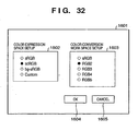
- Fig. 32 shows an example of a user interface used when the user sets a color expression space used to exchange data with other apparatuses, and a color conversion work space used inside the respective image processing apparatuses using the color space information setting units 1018,1212, and 1313.
- a color expression space setup window 1602 a color expression space used to exchange data with other apparatuses is set.
- sRGB, scRGB, bg-sRGB, and a color space which can be customized by the user are presented, and scRGB is selected as the color expression space.
- a color conversion work space setup window 1603 a color conversion work space used in each image processing apparatus is set. In this case, as examples of the color conversion work space, sRGB, RGB2, RGB3, RGB4, and RGB5 are presented, and RGB2 is selected as the color conversion work space.
- the user Upon completion of the setups, the user presses an OK button 1604. If the user wants to cancel the setups, he or she presses a cancel button 1605.
- the user upon exchanging image data among color image input/output devices or in image processes such as color conversion and the like, the user can individually set a color expression space used to exchange image data between the devices, and a color conversion work space used in the color conversion process inside the device.
- Fig. 33 shows an example of image data to be exchanged among the input-side image processing apparatus 1001, display-side image processing apparatus 1002, and output-side image processing apparatus 1003.
- the color expression space information and color conversion work space information set in the third to fifth examples are appended to image data, and the processes in each image processing apparatus use the appended information to execute color conversion processes.
- the color expression space information includes definition equations (14) to (17) or their coefficients
- the color conversion work space information includes definition equations (12) and (13), their coefficients, or information shown in Figs. 27A and 27B .
- a color expression space used to exchange image data between the devices, and a color conversion work space used in the color conversion process inside the device can be individually set by appending them to an image.
- Embodiment can be applied to a system constituted by a plurality of devices (e.g., host computer, interface, reader, printer) or to an apparatus comprising a single device (e.g., copying machine, facsimile machine).
- devices e.g., host computer, interface, reader, printer
- apparatus comprising a single device (e.g., copying machine, facsimile machine).
- the object of the present invention can also be achieved by providing a storage medium storing program codes for performing the aforesaid processes to a computer system or apparatus (e.g., a personal computer), reading the program codes, by a CPU or MPU of the computer system or apparatus, from the storage medium, then executing the program.
- a computer system or apparatus e.g., a personal computer
- the program codes read from the storage medium realize the functions according to the embodiments, and the storage medium storing the program codes constitutes the invention.
- the storage medium such as a floppy disk, a hard disk, an optical disk, a magneto-optical disk, CD-ROM, CD-R, a magnetic tape, a non-volatile type memory card, and ROM can be used for providing the program codes.
- the present invention includes a case where an OS (operating system) or the like working on the computer performs a part or entire processes in accordance with designations of the program codes and realizes functions according to the above embodiments.
- the present invention also includes a case where, after the program codes read from the storage medium are written in a function expansion card which is inserted into the computer or in a memory provided in a function expansion unit which is connected to the computer, CPU or the like contained in the function expansion card or unit performs a part or entire process in accordance with designations of the program codes and realizes functions of the above embodiments.
Landscapes
- Engineering & Computer Science (AREA)
- Multimedia (AREA)
- Signal Processing (AREA)
- Physics & Mathematics (AREA)
- General Physics & Mathematics (AREA)
- Theoretical Computer Science (AREA)
- Image Processing (AREA)
- Color Image Communication Systems (AREA)
- Facsimile Image Signal Circuits (AREA)
Claims (8)
- Bildverarbeitungsverfahren zum Verarbeiten von Bilddaten zwischen Einrichtungen, die ein Bild eingeben/ausgeben, umfassend:einen Schritt des Eingebens (S201) von Bilddaten in einen ersten Farbraum mit drei Dimensionen (scRGB);einen ersten Konvertierschritt (S202) des Konvertierens der eingegebenen Bilddaten vom ersten Farbraum in einen zweiten Farbraum (XYZ);einen Schritt des Erhaltens (S203) von Information, die einen für Menschen sichtbaren Bereich angibt und im zweiten Farbraum definiert ist;einen Schritt des Bestimmens (S204), ob oder nicht die eingegebenen Bilddaten im zweiten Farbraum Bilddaten enthalten, die außerhalb des für Menschen sichtbaren Bereichs fallen, basierend auf der den für Menschen sichtbaren Bereich angebenden Information; undeinen zweiten Konvertierschritt (S206) des Konvertierens der Bilddaten, von denen bestimmt ist, dass sie außerhalb des für Menschen sichtbaren Bereichs fallen, in eine Farbe auf der Grenze des für Menschen sichtbaren Bereichs oder innerhalb des für Menschen sichtbaren Bereichs darstellender Bilddaten, basierend auf der den für Menschen sichtbaren Bereich angebenden Information,wobei der für Menschen sichtbare Bereich ein Gebiet im xy-Chromatizitätsdiagramm angibt, das von einer Spektralfarblinie und einer Purpurlinie umgeben ist und einen Farbwiedergabebereich angibt, der ein sichtbarer Bereich für Menschen ist.
- Verfahren nach Anspruch 1, weiterhin umfassend einen Schritt des Einstellens (S504) eines Konvertierungsverfahrens des zweiten Konvertierschritts.
- Verfahren nach Anspruch 2, wobei der zweite Konvertierschritt (S206) das Konvertieren der eingegebenen Bilddaten vom zweiten Farbraum (XYZ) in einen dritten Farbraum (Lab, LCh) umfasst und eines von Farbunterschiedsminimierung, Helligkeitserhaltung, Farbwerterhaltung und Farbsättigungserhaltung als Konvertierungsverfahren (S206) auswählbar ist.
- Verfahren nach Anspruch 3, weiterhin umfassend einen Schritt des Einstellens (S504) einer Konvertierungsbedingung der Konvertierung.
- Verfahren nach Anspruch 4, wobei aus Farbsättigungsbevorzugung, Farbunterschiedsbevorzugung, Farbdichtebevorzugung und Helligkeitsbevorzugung eine als Konvertierungsbedingung auswählbar ist.
- Bildverarbeitungsvorrichtung zum Verbinden von Bildeingabe-/Bildausgabeeinrichtungen, umfassend:einen Eingabeabschnitt (5), ausgebildet zum Eingeben von Bilddaten in einen ersten Farbraum mit drei Dimensionen (scRGB);einen ersten Konvertierer (8), ausgebildet zum Konvertieren der eingegebenen Bilddaten vom ersten Farbraum in einen zweiten Farbraum (XYZ);einen Speicher (12), ausgebildet zum Speichern von Information, die einen für Menschen sichtbaren Bereich angibt und im zweiten Farbraum definiert ist;einen Bestimmer (9), ausgebildet zum Bestimmen, ob oder nicht die eingegebenen Bilddaten im zweiten Farbraum Bilddaten enthalten, die außerhalb des für Menschen sichtbaren Bereichs fallen, basierend auf der den für Menschen sichtbaren Bereich angebenden Information; undeinen zweiten Konvertierer (10), ausgebildet zum Konvertieren der Bilddaten, von denen bestimmt ist, dass sie außerhalb des für Menschen sichtbaren Bereichs fallen, in eine Farbe auf der Grenze des für Menschen sichtbaren Bereichs oder innerhalb des für Menschen sichtbaren Bereichs darstellender Bilddaten, basierend auf der den für Menschen sichtbaren Bereich angebenden Information,wobei der für Menschen sichtbare Bereich ein Gebiet im xy-Chromatizitätsdiagramm angibt, das von einer Spektralfarblinie und einer Purpurlinie umgeben ist und einen Farbwiedergabebereich angibt, der ein sichtbarer Bereich für Menschen ist.
- Computerprogramm, das, wenn es auf einem Computer ausgeführt wird, den Computer veranlasst, das Verfahren nach einem der Ansprüche 1 bis 5 durchzuführen.
- Computerprogrammprodukt mit einem darauf gespeichertem Computerprogramm nach Anspruch 7.
Applications Claiming Priority (5)
| Application Number | Priority Date | Filing Date | Title |
|---|---|---|---|
| JP2002255244A JP3754944B2 (ja) | 2002-08-30 | 2002-08-30 | 画像処理装置およびその方法 |
| JP2002255244 | 2002-08-30 | ||
| JP2002279371 | 2002-09-25 | ||
| JP2002279371A JP2004120217A (ja) | 2002-08-30 | 2002-09-25 | 画像処理装置、画像処理方法、プログラムおよび記録媒体 |
| PCT/JP2003/011047 WO2004028143A1 (en) | 2002-08-30 | 2003-08-29 | Image processing apparatus and method |
Publications (3)
| Publication Number | Publication Date |
|---|---|
| EP1532806A1 EP1532806A1 (de) | 2005-05-25 |
| EP1532806A4 EP1532806A4 (de) | 2005-09-14 |
| EP1532806B1 true EP1532806B1 (de) | 2014-07-23 |
Family
ID=32032847
Family Applications (1)
| Application Number | Title | Priority Date | Filing Date |
|---|---|---|---|
| EP03797533.1A Expired - Lifetime EP1532806B1 (de) | 2002-08-30 | 2003-08-29 | Bildverarbeitungsvorrichtung und verfahren |
Country Status (8)
| Country | Link |
|---|---|
| US (1) | US7173736B2 (de) |
| EP (1) | EP1532806B1 (de) |
| JP (1) | JP2004120217A (de) |
| KR (1) | KR100673493B1 (de) |
| CN (1) | CN100380912C (de) |
| AU (1) | AU2003263590A1 (de) |
| RU (1) | RU2291585C2 (de) |
| WO (1) | WO2004028143A1 (de) |
Families Citing this family (35)
| Publication number | Priority date | Publication date | Assignee | Title |
|---|---|---|---|---|
| US7609425B2 (en) | 2003-01-31 | 2009-10-27 | Canon Kabushiki Kaisha | Image data processing apparatus, method, storage medium and program |
| JP4721398B2 (ja) | 2004-03-31 | 2011-07-13 | キヤノン株式会社 | 色処理装置およびその方法 |
| JP4343752B2 (ja) | 2004-03-31 | 2009-10-14 | キヤノン株式会社 | 色処理装置およびその方法 |
| US7626742B2 (en) * | 2005-02-16 | 2009-12-01 | Samsung Electronics Co., Ltd. | Color data conversion apparatus and method using gamut boundary descriptors |
| JP2007053521A (ja) * | 2005-08-17 | 2007-03-01 | Seiko Epson Corp | 画像データ変換装置、印刷装置、画像データ変換方法、印刷方法、および変換テーブル作成方法 |
| CA2620627C (en) | 2005-08-30 | 2011-03-15 | Lg Electronics Inc. | Apparatus for encoding and decoding audio signal and method thereof |
| CN100464568C (zh) * | 2005-10-31 | 2009-02-25 | 台湾新力国际股份有限公司 | 影像处理系统 |
| US8130235B2 (en) * | 2005-12-19 | 2012-03-06 | Sony Ericsson Mobile Communications Ab | Apparatus and method of automatically adjusting a display experiencing varying lighting conditions |
| KR100843088B1 (ko) | 2006-08-16 | 2008-07-02 | 삼성전자주식회사 | 광색역 공간의 영상을 출력하는 장치 및 방법 |
| JP4063306B1 (ja) * | 2006-09-13 | 2008-03-19 | ソニー株式会社 | 画像処理装置、画像処理方法、及びプログラム |
| JP4730837B2 (ja) * | 2006-09-15 | 2011-07-20 | 株式会社リコー | 画像処理方法、画像処理装置、プログラムおよび記録媒体 |
| RU2442215C2 (ru) * | 2006-10-18 | 2012-02-10 | Конинклейке Филипс Электроникс Н.В. | Система формирования изображений, способ формирования изображений и компьютерная программа для формирования изображения интересующей области |
| KR101236774B1 (ko) * | 2006-12-22 | 2013-02-25 | 리더 덴시 가부시키 가이샤 | 영상신호 감시장치 및 방법 |
| US20090033755A1 (en) * | 2007-08-03 | 2009-02-05 | Tandent Vision Science, Inc. | Image acquisition and processing engine for computer vision |
| US8199184B2 (en) * | 2007-11-06 | 2012-06-12 | Cisco Technology, Inc. | Visually enhancing a conference |
| US8564828B2 (en) * | 2007-11-09 | 2013-10-22 | Xerox Corporation | Automated methods and systems for assessing and summarizing gamut requirements |
| US20090185202A1 (en) * | 2008-01-18 | 2009-07-23 | Xerox Corporation | Methods and systems for selecting printing materials |
| US20090185203A1 (en) * | 2008-01-18 | 2009-07-23 | Xerox Corporation | Methods and systems for automated load balancing of color print jobs |
| JP4542600B2 (ja) * | 2009-01-13 | 2010-09-15 | シャープ株式会社 | 映像表示装置 |
| KR101295881B1 (ko) * | 2009-07-10 | 2013-08-12 | 엘지디스플레이 주식회사 | 선호색 보정방법과 이를 이용한 표시장치 |
| US8576445B2 (en) * | 2011-06-28 | 2013-11-05 | Konica Minolta Laboratory U.S.A., Inc. | Method for processing high dynamic range images using tone mapping to extended RGB space |
| JP2015049463A (ja) * | 2013-09-03 | 2015-03-16 | ソニー株式会社 | 情報処理装置、情報処理方法、プログラム、及び画像表示装置 |
| US9179042B2 (en) | 2013-10-09 | 2015-11-03 | Dolby Laboratories Licensing Corporation | Systems and methods to optimize conversions for wide gamut opponent color spaces |
| KR102284995B1 (ko) | 2014-06-19 | 2021-08-04 | 브이아이디 스케일, 인크. | 3차원 기반 컬러 매핑에서의 모델 파라미터 최적화를 위한 시스템 및 방법 |
| KR20160059240A (ko) * | 2014-11-18 | 2016-05-26 | 삼성전자주식회사 | 색 재현 영역을 표시하는 방법 및 장치 |
| WO2017157467A1 (en) * | 2016-03-18 | 2017-09-21 | Hp Indigo B.V. | Color mapping with phosphorescent materials |
| EP3544280B1 (de) * | 2016-11-17 | 2024-04-03 | Panasonic Intellectual Property Management Co., Ltd. | Bildverarbeitungsvorrichtung, bildverarbeitungsverfahren und programm |
| WO2018092711A1 (ja) * | 2016-11-17 | 2018-05-24 | パナソニックIpマネジメント株式会社 | 画像処理装置、画像処理方法、およびプログラム |
| JP6939197B2 (ja) | 2017-07-28 | 2021-09-22 | セイコーエプソン株式会社 | 情報処理装置、プログラム、及び情報処理装置の制御方法 |
| JP2020036278A (ja) * | 2018-08-31 | 2020-03-05 | キヤノン株式会社 | 画像処理装置、その制御方法、及びプログラム |
| CN110930963B (zh) * | 2019-11-14 | 2021-03-16 | Tcl华星光电技术有限公司 | 色域映射方法和色域处理系统 |
| TWI759669B (zh) * | 2019-12-23 | 2022-04-01 | 中強光電股份有限公司 | 顯示畫面檢測方法與顯示畫面檢測系統 |
| JP7521474B2 (ja) | 2021-03-31 | 2024-07-24 | ブラザー工業株式会社 | 色設定プログラム、色設定方法、および色設定装置 |
| JP7435525B2 (ja) * | 2021-03-31 | 2024-02-21 | ブラザー工業株式会社 | 色設定プログラム、色設定方法、および色設定装置 |
| CN117392023A (zh) * | 2022-06-30 | 2024-01-12 | 北京小米移动软件有限公司 | 图像处理方法及装置、电子设备、存储介质 |
Citations (1)
| Publication number | Priority date | Publication date | Assignee | Title |
|---|---|---|---|---|
| JPH11328392A (ja) * | 1998-05-19 | 1999-11-30 | Konica Corp | 画像処理装置 |
Family Cites Families (37)
| Publication number | Priority date | Publication date | Assignee | Title |
|---|---|---|---|---|
| JP3099344B2 (ja) * | 1990-06-05 | 2000-10-16 | 富士ゼロックス株式会社 | 画像処理装置 |
| CN1031540C (zh) | 1990-09-19 | 1996-04-10 | 菲利浦光灯制造公司 | 记录载体、主数据和控制文件的记录方法和装置及读出装置 |
| US5933252A (en) * | 1990-11-21 | 1999-08-03 | Canon Kabushiki Kaisha | Color image processing method and apparatus therefor |
| JPH04186969A (ja) | 1990-11-21 | 1992-07-03 | Canon Inc | カラー画像処理装置 |
| US5422739A (en) * | 1991-07-08 | 1995-06-06 | Canon Kabushiki Kaisha | Color expressing method, color image reading apparatus and color image processing apparatus |
| JP3143508B2 (ja) * | 1992-01-08 | 2001-03-07 | キヤノン株式会社 | 画像処理方法及び装置 |
| US5510910A (en) * | 1992-05-04 | 1996-04-23 | Hewlett-Packard Company | Printing with full printer color gamut, through use of gamut superposition in a common perceptual space |
| US5377024A (en) * | 1992-05-04 | 1994-12-27 | Hewlett-Packard | Apparatus for forming color images using a hue-plus-gray color model |
| US5473446A (en) * | 1992-05-04 | 1995-12-05 | Hewlett-Packard Company | Color digital halftoning using black and secondary color replacement and color vector dithering |
| US5883632A (en) * | 1992-05-04 | 1999-03-16 | Hewlett-Packard Company | Coordinating color produced by two devices--using a hue-controlled machine color space, or surface scaling |
| US5657137A (en) * | 1992-05-04 | 1997-08-12 | Hewlett-Packard Company | Color digital halftoning using black and secondary color replacement |
| JPH0690351A (ja) * | 1992-09-09 | 1994-03-29 | Fujitsu Ltd | カラー画像の色圧縮方式 |
| DE69329186T2 (de) * | 1993-01-01 | 2001-04-05 | Canon Kk | Bildlesevorrichtung |
| JPH07160871A (ja) * | 1993-12-09 | 1995-06-23 | Mieko Nagashima | 色画像補正方法及びその装置 |
| JPH07222011A (ja) * | 1994-01-31 | 1995-08-18 | Canon Inc | 色再現範囲表現方法及び画像処理方法及び装置 |
| EP0675638A3 (de) * | 1994-03-31 | 1996-01-24 | Canon Kk | Farbbildverarbeitungsverfahren und dieses benutzendes Gerät. |
| US5650942A (en) * | 1996-02-02 | 1997-07-22 | Light Source Computer Images, Inc. | Appearance-based technique for rendering colors on an output device |
| US6225974B1 (en) * | 1997-06-19 | 2001-05-01 | Electronics For Imaging, Inc. | Gamut correction with color separation and methods and apparatuses for performing same |
| JPH11187419A (ja) * | 1997-12-24 | 1999-07-09 | Sony Corp | 信号処理装置及び信号処理方法 |
| JPH11275377A (ja) * | 1998-03-25 | 1999-10-08 | Fujitsu Ltd | カラーデータ変換方法及びその装置 |
| US6181445B1 (en) * | 1998-03-30 | 2001-01-30 | Seiko Epson Corporation | Device-independent and medium-independent color matching between an input device and an output device |
| US6771314B1 (en) * | 1998-03-31 | 2004-08-03 | Intel Corporation | Orange-green-blue (OGB) color system for digital image sensor applications |
| US6999617B1 (en) * | 1998-07-24 | 2006-02-14 | Canon Kabushiki Kaisha | Image processing method and apparatus |
| JP2000123163A (ja) * | 1998-10-19 | 2000-04-28 | Canon Inc | 画像処理装置及びその方法 |
| US6211971B1 (en) | 1999-03-11 | 2001-04-03 | Lockheed Martin Missiles & Space Co. | Method and apparatus to compress multi-spectral images to a single color image for display |
| JP2000324350A (ja) | 1999-05-13 | 2000-11-24 | Matsushita Electric Ind Co Ltd | 色変換装置 |
| WO2001017233A1 (en) * | 1999-08-27 | 2001-03-08 | Microsoft Corporation | Visually error-free color image representation |
| US6985524B1 (en) * | 1999-09-01 | 2006-01-10 | Sharp Laboratories Of America, Inc. | Apparatus and method for adjusting real time video to compensate for color blindness |
| US6822760B1 (en) | 2000-04-05 | 2004-11-23 | Eastman Kodak Company | Method of processing and paying for an extended color gamut digital image |
| RU2190306C2 (ru) * | 2000-05-10 | 2002-09-27 | Государственное унитарное предприятие "Калужский научно-исследовательский институт телемеханических устройств" | Способ обработки цветного полутонового изображения с использованием векторной диффузии ошибки цвета и устройство для его осуществления |
| US6738151B1 (en) * | 2000-05-26 | 2004-05-18 | Kabushiki Kaisha Toshiba | Distributed processing system for image forming apparatus |
| US6870523B1 (en) * | 2000-06-07 | 2005-03-22 | Genoa Color Technologies | Device, system and method for electronic true color display |
| JP2002109523A (ja) * | 2000-09-28 | 2002-04-12 | Minolta Co Ltd | 撮像装置、光学フィルタ群および画像データ変換装置 |
| JP3676664B2 (ja) * | 2000-11-10 | 2005-07-27 | 日本電信電話株式会社 | 均等色空間構成方法および当該構成のための装置および当該方法を記録した記録媒体 |
| DE60229338D1 (de) * | 2001-09-07 | 2008-11-27 | Canon Kk | Bildverarbeitungsverfahren und -gerät |
| JP4061907B2 (ja) | 2002-01-15 | 2008-03-19 | セイコーエプソン株式会社 | 画像処理済み画像データの出力および保存 |
| US7450281B2 (en) * | 2002-04-30 | 2008-11-11 | Canon Kabushiki Kaisha | Image processing apparatus and information processing apparatus, and method thereof |
-
2002
- 2002-09-25 JP JP2002279371A patent/JP2004120217A/ja active Pending
-
2003
- 2003-08-29 KR KR1020047016459A patent/KR100673493B1/ko not_active Expired - Fee Related
- 2003-08-29 EP EP03797533.1A patent/EP1532806B1/de not_active Expired - Lifetime
- 2003-08-29 RU RU2004133066/09A patent/RU2291585C2/ru not_active IP Right Cessation
- 2003-08-29 AU AU2003263590A patent/AU2003263590A1/en not_active Abandoned
- 2003-08-29 CN CNB038072947A patent/CN100380912C/zh not_active Expired - Fee Related
- 2003-08-29 WO PCT/JP2003/011047 patent/WO2004028143A1/en not_active Ceased
-
2004
- 2004-09-02 US US10/932,000 patent/US7173736B2/en not_active Expired - Lifetime
Patent Citations (1)
| Publication number | Priority date | Publication date | Assignee | Title |
|---|---|---|---|---|
| JPH11328392A (ja) * | 1998-05-19 | 1999-11-30 | Konica Corp | 画像処理装置 |
Also Published As
| Publication number | Publication date |
|---|---|
| CN1643894A (zh) | 2005-07-20 |
| WO2004028143A1 (en) | 2004-04-01 |
| AU2003263590A1 (en) | 2004-04-08 |
| KR100673493B1 (ko) | 2007-01-24 |
| EP1532806A1 (de) | 2005-05-25 |
| RU2004133066A (ru) | 2005-04-20 |
| KR20050023245A (ko) | 2005-03-09 |
| CN100380912C (zh) | 2008-04-09 |
| EP1532806A4 (de) | 2005-09-14 |
| JP2004120217A (ja) | 2004-04-15 |
| US20050024662A1 (en) | 2005-02-03 |
| RU2291585C2 (ru) | 2007-01-10 |
| US7173736B2 (en) | 2007-02-06 |
Similar Documents
| Publication | Publication Date | Title |
|---|---|---|
| EP1532806B1 (de) | Bildverarbeitungsvorrichtung und verfahren | |
| EP0665680B1 (de) | Bildverarbeitungsvorrichtung und -verfahren | |
| EP1301025B1 (de) | Verfahren und Vorrichtung zur Erzeugung einer Farbkorrekturtabelle, Steuerprogramm und Speichermedium | |
| EP1526712B1 (de) | Verfahren zur Umsetzung von Farbdaten | |
| EP1909486B1 (de) | Verfahren und Vorrichtung zur Durchführung eines Skalenabgleichs zwischen heterogenen Geräten | |
| JP3143508B2 (ja) | 画像処理方法及び装置 | |
| US7239425B2 (en) | Color processing method and apparatus for generating a conversion condition for converting data in a device independent color space into data in a device dependent color space | |
| CN103108106B (zh) | 图像处理装置 | |
| US8427696B2 (en) | Color processing method and apparatus thereof | |
| JP2001045310A (ja) | 画像処理装置、方法および記録媒体 | |
| JP2008244613A (ja) | 画像出力機器の色変換定義の作成方法、そのプログラム及び記録媒体、ならびに画像出力機器および画像処理装置 | |
| US7986448B2 (en) | Image processing apparatus and image processing method for the same | |
| US20060232803A1 (en) | Image processing method, profile creation method, and image processing apparatus | |
| US7616361B2 (en) | Color processing apparatus and its method | |
| WO2006109859A1 (en) | Color processing method and apparatus | |
| JP3754944B2 (ja) | 画像処理装置およびその方法 | |
| JP4545995B2 (ja) | 画像処理方法及び画像処理装置 | |
| US7483172B2 (en) | Image processing apparatus and image processing method | |
| JP2005130537A (ja) | 画像処理装置およびその方法 | |
| JP4250609B2 (ja) | 色処理方法、装置および記録媒体 | |
| US10477038B2 (en) | Image processing apparatus, image processing system, and recording medium | |
| JP2003087590A (ja) | 画像処理方法及び画像処理装置 | |
| JP2007166308A (ja) | データ圧縮処理装置および方法および記録媒体 | |
| JP2008211289A (ja) | 画像処理装置、画像処理システム、及び画像処理プログラム。 |
Legal Events
| Date | Code | Title | Description |
|---|---|---|---|
| PUAI | Public reference made under article 153(3) epc to a published international application that has entered the european phase |
Free format text: ORIGINAL CODE: 0009012 |
|
| 17P | Request for examination filed |
Effective date: 20040923 |
|
| AK | Designated contracting states |
Kind code of ref document: A1 Designated state(s): AT BE BG CH CY CZ DE DK EE ES FI FR GB GR HU IE IT LI LU MC NL PT RO SE SI SK TR |
|
| AX | Request for extension of the european patent |
Extension state: AL LT LV MK |
|
| A4 | Supplementary search report drawn up and despatched |
Effective date: 20050803 |
|
| DAX | Request for extension of the european patent (deleted) | ||
| RBV | Designated contracting states (corrected) |
Designated state(s): DE ES FR GB NL |
|
| 17Q | First examination report despatched |
Effective date: 20090609 |
|
| GRAP | Despatch of communication of intention to grant a patent |
Free format text: ORIGINAL CODE: EPIDOSNIGR1 |
|
| INTG | Intention to grant announced |
Effective date: 20140214 |
|
| GRAS | Grant fee paid |
Free format text: ORIGINAL CODE: EPIDOSNIGR3 |
|
| GRAA | (expected) grant |
Free format text: ORIGINAL CODE: 0009210 |
|
| AK | Designated contracting states |
Kind code of ref document: B1 Designated state(s): DE ES FR GB NL |
|
| REG | Reference to a national code |
Ref country code: GB Ref legal event code: FG4D |
|
| REG | Reference to a national code |
Ref country code: DE Ref legal event code: R096 Ref document number: 60346540 Country of ref document: DE Effective date: 20140904 |
|
| REG | Reference to a national code |
Ref country code: NL Ref legal event code: VDEP Effective date: 20140723 |
|
| PG25 | Lapsed in a contracting state [announced via postgrant information from national office to epo] |
Ref country code: ES Free format text: LAPSE BECAUSE OF FAILURE TO SUBMIT A TRANSLATION OF THE DESCRIPTION OR TO PAY THE FEE WITHIN THE PRESCRIBED TIME-LIMIT Effective date: 20140723 |
|
| PG25 | Lapsed in a contracting state [announced via postgrant information from national office to epo] |
Ref country code: NL Free format text: LAPSE BECAUSE OF FAILURE TO SUBMIT A TRANSLATION OF THE DESCRIPTION OR TO PAY THE FEE WITHIN THE PRESCRIBED TIME-LIMIT Effective date: 20140723 |
|
| REG | Reference to a national code |
Ref country code: DE Ref legal event code: R097 Ref document number: 60346540 Country of ref document: DE |
|
| PLBE | No opposition filed within time limit |
Free format text: ORIGINAL CODE: 0009261 |
|
| REG | Reference to a national code |
Ref country code: FR Ref legal event code: ST Effective date: 20150430 |
|
| STAA | Information on the status of an ep patent application or granted ep patent |
Free format text: STATUS: NO OPPOSITION FILED WITHIN TIME LIMIT |
|
| 26N | No opposition filed |
Effective date: 20150424 |
|
| PG25 | Lapsed in a contracting state [announced via postgrant information from national office to epo] |
Ref country code: FR Free format text: LAPSE BECAUSE OF NON-PAYMENT OF DUE FEES Effective date: 20140923 |
|
| PGFP | Annual fee paid to national office [announced via postgrant information from national office to epo] |
Ref country code: GB Payment date: 20220721 Year of fee payment: 20 Ref country code: DE Payment date: 20220616 Year of fee payment: 20 |
|
| REG | Reference to a national code |
Ref country code: DE Ref legal event code: R071 Ref document number: 60346540 Country of ref document: DE |
|
| REG | Reference to a national code |
Ref country code: GB Ref legal event code: PE20 Expiry date: 20230828 |
|
| PG25 | Lapsed in a contracting state [announced via postgrant information from national office to epo] |
Ref country code: GB Free format text: LAPSE BECAUSE OF EXPIRATION OF PROTECTION Effective date: 20230828 |