EP1531224A2 - Treibstangenbeschlag - Google Patents
Treibstangenbeschlag Download PDFInfo
- Publication number
- EP1531224A2 EP1531224A2 EP04104756A EP04104756A EP1531224A2 EP 1531224 A2 EP1531224 A2 EP 1531224A2 EP 04104756 A EP04104756 A EP 04104756A EP 04104756 A EP04104756 A EP 04104756A EP 1531224 A2 EP1531224 A2 EP 1531224A2
- Authority
- EP
- European Patent Office
- Prior art keywords
- drive
- drive rod
- espagnolette fitting
- rods
- trough
- Prior art date
- Legal status (The legal status is an assumption and is not a legal conclusion. Google has not performed a legal analysis and makes no representation as to the accuracy of the status listed.)
- Withdrawn
Links
Images

Classifications
-
- E—FIXED CONSTRUCTIONS
- E05—LOCKS; KEYS; WINDOW OR DOOR FITTINGS; SAFES
- E05C—BOLTS OR FASTENING DEVICES FOR WINGS, SPECIALLY FOR DOORS OR WINDOWS
- E05C9/00—Arrangements of simultaneously actuated bolts or other securing devices at well-separated positions on the same wing
- E05C9/06—Arrangements of simultaneously actuated bolts or other securing devices at well-separated positions on the same wing with three or more sliding bars
- E05C9/063—Arrangements of simultaneously actuated bolts or other securing devices at well-separated positions on the same wing with three or more sliding bars extending along three or more sides of the wing or frame
- E05C9/066—Locks for windows or doors specially adapted for tilt and turn
-
- E—FIXED CONSTRUCTIONS
- E05—LOCKS; KEYS; WINDOW OR DOOR FITTINGS; SAFES
- E05C—BOLTS OR FASTENING DEVICES FOR WINGS, SPECIALLY FOR DOORS OR WINDOWS
- E05C9/00—Arrangements of simultaneously actuated bolts or other securing devices at well-separated positions on the same wing
- E05C9/04—Arrangements of simultaneously actuated bolts or other securing devices at well-separated positions on the same wing with two sliding bars moved in opposite directions when fastening or unfastening
- E05C9/041—Arrangements of simultaneously actuated bolts or other securing devices at well-separated positions on the same wing with two sliding bars moved in opposite directions when fastening or unfastening with rack and pinion mechanism
Definitions
- the invention relates to a drive rod fitting for Locking a sash in a frame of a window, a French window or the like with a longitudinally displaceable guided drive rod, with several of the Drive rod drivable closing elements and with at least a the locking elements to be arranged opposite Striker for receiving the closing elements in a closed position.
- Such a drive rod fitting is for example off DE 198 13 166 A1 discloses.
- the closing elements are designed as swiveling hooks and are over each one connected to the drive rod toothed rod driven in opposite directions.
- the opposite drive the hook is created by one of the hooks a sprocket on the drive rod facing Side and the other the hook a sprocket at the Drive rod has remote side of the drive rod.
- the opposite drive of the closing elements is that by shifting the wing in one direction the closing elements are not out of the Press out strike plates.
- the known Espagnolette fitting therefore offers high protection against a press of the window.
- the invention is based on the problem, a Espagnolette fitting of the type mentioned above to be designed so that it is as simple as possible and inexpensive is to produce.
- the closing elements are rigid arranged the drive rod, creating a complex storage is avoided.
- the fastening of the closing elements directly on the espagnolettes has the advantage of being there In the simplest case, these are equal parts can. This leads to a further reduction in manufacturing costs of the espagnolette invention.
- As a closing element is almost every component, which are fixed on the drive rods and can interact with the strike plate, such as Mushroom heads, hook-shaped elements or the like.
- the driving rod fitting according to the invention is This makes it very easy to set up.
- espagnolette according to the invention has a special low friction, when the coupling means on a stationary component stored, with the two Have driving rods engaging gear.
- the driving rod fitting according to the invention requires a particularly small installation space, if the drive rods over each other are guided and if the gear between the Espagnolettes is arranged.
- the drive rod fitting according to the invention is designed particularly compact, if one of the drive rods is a trough-shaped Has recess for receiving the gear.
- the drive rod fitting according to the invention is designed structurally particularly simple when compared to the Driving rod with the trough-shaped recess in opposite directions guided drive rod with one end in the trough-shaped Recess protrudes and sandwiched with the other end is guided over the other drive rod.
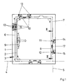
- FIG. 1 shows a frame 1 with a wing 2 and schematically a driving rod fitting 3.
- the wing 2 leaves towards the frame 1 about a horizontal axis. 4 tilt and turn around a vertical axis 5.
- the Espagnolette fitting 3 has several, on the wing. 2 longitudinally displaceable guided rods 6 - 8 and a Handle 9 for driving the drive rods 6 - 8.
- On the Espagnolines 6 - 8 are several closing elements 10 - 12 attached.
- the frame 1 has several, in the area of Closing elements 10 - 12 arranged striking plates 13 - 15. These striking plates 13 - 15 have one for recording the closure elements 10 - 12 corresponding shape and are closed on one side.
- the handle 9th in a position Z, in which the closing elements 10 - 12 are within the strike plates 13 - 15 and the Wing 2 is locked in the frame 1.
- the Espagnolines 6 - 8 are via coupling means 16, 17 with each other connected.
- the coupling means 16, 17 generate at a Drive a first drive rod 6 - 8 an opposite Movement of the subsequent second Drive rod 6 - 8.
- the directions of movement of the closing elements 10 - 12 are in the drawing when moving in the closed position marked with arrows. in this connection it can be seen that adjacent closing elements 10 - 12 in the movement in the closed position from each other away or towards each other.
- the espagnolette 3 more, in have a common direction movable closure elements.
- Figure 2 shows a sectional view through the Espagnolette fitting 3 from Figure 1 along the line II - II. It can be seen here that the closing elements 10 - 12 are designed as mushroom pin and of the one-sided open strike plates 14, 15 are engaged behind. The wing 2 shown in Figure 1 can therefore neither from the frame 1 in the direction of the axis 4, 5 of Closing elements 10 - 12 still pull away parallel to the Driving rods 7, 8 move.
- Figure 3 shows a sectional view through the Espagnolette fitting 3 from Figure 2 along the line III - III with the drive rods 7, 8 and the coupling means 17th from Figure 1.
- the drive rods 7, 8 are below a Cuff rail 18 out.
- the faceplate 18 has slots 19, 20 for performing the closing elements 11, 12th on.
- One of the drive rods 7 has a trough-shaped depression 21 for receiving a gear 22 of the coupling means 17.
- the gear 22 meshes with the drive rods 7, 8th arranged racks 23, 24.
- the storage of the gear 22 is firmly connected to the faceplate 18, so that the gear 22 when driving one of the drive rods 7, 8 remains in its illustrated position and the Movement on the other of the drive rods 7, 8 transmits.
- the Gear 22 is in a trough-shaped recess 25 a the drive rods 7 arranged.
- the drive rods 7, 8 are sandwiched one above the other, so that either one drive rod 7, 8 or the other Driving rod 7, 8 to the next in Figure 1 shown Closing element 10 can be performed.
- FIG. 4 shows a further embodiment of the coupling means 17 ', in which one of the drive rods 8' and a gear 22 'of the coupling means 17' completely within a trough-shaped Recess 21 'of the other drive rod 7' arranged is.
- the trough-shaped recess 21 'having Driving rod 7 ' is shown in FIG Handle 9 driven.
- in the coupling means 17 ' 4 shows the movement of the driven drive rod 7 ' to the next, shown in Figure 1 closing element 10 transmitted.
Landscapes
- Engineering & Computer Science (AREA)
- Mechanical Engineering (AREA)
- Power-Operated Mechanisms For Wings (AREA)
- Specific Sealing Or Ventilating Devices For Doors And Windows (AREA)
Abstract
Description
- Fig. 1
- schematisch einen erfindungsgemäßen Treibstangenbeschlag,
- Fig. 2
- eine Schnittdarstellung durch den Treibstangenbeschlag aus Figur 1 entlang der Linie II - II,
- Fig. 3
- eine Schnittdarstellung durch den Treibstangenbeschlag aus Figur 1 im Bereich von Koppelmitteln entlang der Linie III - III aus Figur 2,
- Fig. 4
- eine weitere Schnittdarstellung durch den Treibstangenbeschlag aus Figur 1 im Bereich von Koppelmitteln.
Claims (7)
- Treibstangenbeschlag zur Verriegelung eines Flügels in einem Rahmen eines Fensters, einer Fenstertür oder dergleichen mit einer längsverschieblich geführten Treibstange, mit mehreren von der Treibstange antreibbaren Schließelementen und mit zumindest einem den Schließelementen gegenüberstehend anzuordnenden Schließblech zur Aufnahme der Schließelemente in einer Schließstellung, dadurch gekennzeichnet, dass zwei nebeneinander angeordnete Schließelemente (10 - 12) auf unterschiedlichen Treibstangen (6 - 8, 7', 8') befestigt sind, dass die Treibstangen (6 - 8, 7', 8') über Koppelmittel (16, 17, 17') miteinander verbunden sind und dass die Koppelmittel (16, 17, 17') zum gegenläufigen Antrieb der zweiten Treibstange (6 - 8, 7', 8') bei einem Antrieb der ersten Treibstange (6 - 8, 7', 8') ausgebildet sind.
- Treibstangenbeschlag nach Anspruch 1, dadurch gekennzeichnet, dass der Treibstangenbeschlag (3) an zumindest zwei Holmen des Flügels (2) oder des Rahmens (1) jeweils einander gegenläufig angetriebene Treibstangen (6 - 8, 7', 8') hat.
- Treibstangenbeschlag nach Anspruch 1 oder 2, dadurch gekennzeichnet, dass die Koppelmittel (17, 17') ein an einem feststehenden Bauteil gelagertes, mit den beiden Treibstangen (7, 7', 8, 8') in Eingriff stehendes Zahnrad (22, 22') aufweisen.
- Treibstangenbeschlag nach zumindest einem der vorhergehenden Ansprüche, dadurch gekennzeichnet, dass die Treibstangen (7, 7', 8, 8') übereinander geführt sind und dass das Zahnrad (22, 22') zwischen den Treibstangen (7, 7', 8, 8') angeordnet ist.
- Treibstangenbeschlag nach zumindest einem der vorhergehenden Ansprüche, dadurch gekennzeichnet, dass eine der Treibstangen (7, 7') eine wannenförmige Vertiefung (21, 21') zur Aufnahme des Zahnrades (22, 22') hat.
- Treibstangenbeschlag nach zumindest einem der vorhergehenden Ansprüche, dadurch gekennzeichnet, dass die gegenüber der Treibstange (7) mit der wannenförmigen Vertiefung (21) gegenläufig geführte Treibstange (8) mit einem Ende in die wannenförmige Vertiefung (21) hineinragt und mit dem anderem Ende sandwichartig über der anderen Treibstange (7) geführt ist.
- Treibstangenbeschlag nach zumindest einem der vorhergehenden Ansprüche, dadurch gekennzeichnet, dass die gegenüber der Treibstange (7') mit der wannenförmigen Vertiefung (21') gegenläufig geführte Treibstange (8') vollständig innerhalb der wannenförmigen Vertiefung (21') angeordnet ist.
Applications Claiming Priority (2)
| Application Number | Priority Date | Filing Date | Title |
|---|---|---|---|
| DE2003152833 DE10352833A1 (de) | 2003-11-12 | 2003-11-12 | Treibstangenbeschlag |
| DE10352833 | 2003-11-12 |
Publications (2)
| Publication Number | Publication Date |
|---|---|
| EP1531224A2 true EP1531224A2 (de) | 2005-05-18 |
| EP1531224A3 EP1531224A3 (de) | 2007-08-01 |
Family
ID=34428692
Family Applications (1)
| Application Number | Title | Priority Date | Filing Date |
|---|---|---|---|
| EP04104756A Withdrawn EP1531224A3 (de) | 2003-11-12 | 2004-09-29 | Treibstangenbeschlag |
Country Status (2)
| Country | Link |
|---|---|
| EP (1) | EP1531224A3 (de) |
| DE (1) | DE10352833A1 (de) |
Cited By (2)
| Publication number | Priority date | Publication date | Assignee | Title |
|---|---|---|---|---|
| GB2436118A (en) * | 2006-03-18 | 2007-09-19 | Trojan Hardware & Designs Ltd | Espagnolette mechanism |
| EP2899341A3 (de) * | 2014-01-24 | 2016-07-13 | MACO Technologie GmbH | Beschlaganordnung |
Families Citing this family (1)
| Publication number | Priority date | Publication date | Assignee | Title |
|---|---|---|---|---|
| CN219622470U (zh) * | 2023-01-04 | 2023-09-01 | 宁德时代新能源科技股份有限公司 | 一种连接组件、储能电柜以及储能系统 |
Family Cites Families (9)
| Publication number | Priority date | Publication date | Assignee | Title |
|---|---|---|---|---|
| DE2557303C2 (de) * | 1975-12-19 | 1978-03-23 | Siegenia-Frank Kg, 5900 Siegen- Kaan-Marienborn | Schubrichtungs-Umkehrgetriebe für Treibstangenbeschläge |
| FR2687185B1 (fr) * | 1992-02-12 | 1994-04-08 | Vachette | Serrure de porte assurant une fonction d'etancheite et une fonction de securite. |
| EP0598927B1 (de) * | 1992-10-29 | 1994-08-17 | W. Hautau Gmbh | Betätigungsgetriebe für Beschläge an Fenstern, Türen oder dergleichen |
| GB2321930B (en) * | 1994-04-22 | 1998-09-30 | Derek King | Shoot bolt window locking system |
| DE19737538C2 (de) * | 1997-08-28 | 2000-11-23 | Siegenia Frank Kg | Befestigungseinrichtung |
| DE10111903C5 (de) * | 2001-03-13 | 2009-06-25 | GAYKO Fenster-Türenwerk GmbH | Abschlusselement für Wandöffnungen |
| DE50305222D1 (de) * | 2002-02-28 | 2006-11-16 | Mayer & Co | Verschlussgetriebe für Flügel von Fenstern, Türen und dergleichen |
| DE10213344A1 (de) * | 2002-03-26 | 2003-10-09 | Wilka Schliestechnik Gmbh | Treibstangenbetätigbarer Hakenriegelverschluss |
| DE10219692A1 (de) * | 2002-05-02 | 2003-11-27 | Roto Frank Ag | Verriegelungsbeschlag an einem Fenster, eienr Tür oder dergleichen, mit gegenläufig verschiebbaren Treibstangen |
-
2003
- 2003-11-12 DE DE2003152833 patent/DE10352833A1/de not_active Ceased
-
2004
- 2004-09-29 EP EP04104756A patent/EP1531224A3/de not_active Withdrawn
Cited By (2)
| Publication number | Priority date | Publication date | Assignee | Title |
|---|---|---|---|---|
| GB2436118A (en) * | 2006-03-18 | 2007-09-19 | Trojan Hardware & Designs Ltd | Espagnolette mechanism |
| EP2899341A3 (de) * | 2014-01-24 | 2016-07-13 | MACO Technologie GmbH | Beschlaganordnung |
Also Published As
| Publication number | Publication date |
|---|---|
| EP1531224A3 (de) | 2007-08-01 |
| DE10352833A1 (de) | 2005-06-23 |
Similar Documents
| Publication | Publication Date | Title |
|---|---|---|
| EP0492341B1 (de) | Verschlussgetriebe für ein zweiflügeliges Fenster, od. dgl. | |
| DE202007015503U1 (de) | Treibstangengetriebe | |
| EP0433623B1 (de) | Verriegelungsvorrichtung für ein Fenster, eine Tür od.dgl. | |
| EP2799648A2 (de) | Kraftfahrzeugschloss | |
| EP2921622B1 (de) | Treibriegelbeschlag | |
| EP1867819B1 (de) | Verschluss für einen Treibstangenbeschlag und Treibstangenbeschlag mit einem solchen Verschluss | |
| DE102012111881A1 (de) | Motorisch betreibbares Standflügelschloss mit Riegel- und Fallenauswerfer | |
| EP2143859B1 (de) | Verriegelungsvorrichtung | |
| EP1681417A2 (de) | Beschlag | |
| EP1531224A2 (de) | Treibstangenbeschlag | |
| DE102007025723B3 (de) | Kupplungseinheit für ein Garagentor, insbesondere Kipp-, Schwenk- oder Sektionaltor | |
| EP2754804B1 (de) | Verschluss für einen Treibstangenbeschlag | |
| EP0761920B1 (de) | Fenster/Tür mit Dreh-Kipp-Beschlag | |
| EP1533453A1 (de) | Kantengetriebe | |
| EP1340872A2 (de) | Schliessvorrichtung | |
| EP3425149A1 (de) | Hebe-schiebe-einrichtung, insbesondere hebe-schiebe-tür oder hebe-schiebe-fenster | |
| DE10212217B4 (de) | Türschloss | |
| DE19745553A1 (de) | Schließvorrichtung | |
| DE3221110A1 (de) | Beschlag fuer einen kipp- und nachfolgend mindestens parallelabstellbaren fluegel eines fensters, einer tuer od. dgl. | |
| EP2348176B1 (de) | Verschluss eines Treibstangenbeschlages | |
| DE102019114188A1 (de) | Stangenverschluss | |
| DE3008043A1 (de) | Zusatzverriegelung fuer fenster, tueren o.dgl. | |
| EP2806090A2 (de) | Vorrichtung zum Verriegeln oder Entriegeln eines Schiebeflügels | |
| DE102019114189A1 (de) | Stangenverschluss mit Eckumlenkung | |
| DE69201798T2 (de) | Verriegelungsvorrichtung. |
Legal Events
| Date | Code | Title | Description |
|---|---|---|---|
| PUAI | Public reference made under article 153(3) epc to a published international application that has entered the european phase |
Free format text: ORIGINAL CODE: 0009012 |
|
| AK | Designated contracting states |
Kind code of ref document: A2 Designated state(s): AT BE BG CH CY CZ DE DK EE ES FI FR GB GR HU IE IT LI LU MC NL PL PT RO SE SI SK TR |
|
| AX | Request for extension of the european patent |
Extension state: AL HR LT LV MK |
|
| PUAL | Search report despatched |
Free format text: ORIGINAL CODE: 0009013 |
|
| AK | Designated contracting states |
Kind code of ref document: A3 Designated state(s): AT BE BG CH CY CZ DE DK EE ES FI FR GB GR HU IE IT LI LU MC NL PL PT RO SE SI SK TR |
|
| AX | Request for extension of the european patent |
Extension state: AL HR LT LV MK |
|
| AKX | Designation fees paid |
Designated state(s): AT BE BG CH CY CZ DE DK EE ES FI FR GB GR HU IE IT LI LU MC NL PL PT RO SE SI SK TR |
|
| STAA | Information on the status of an ep patent application or granted ep patent |
Free format text: STATUS: THE APPLICATION IS DEEMED TO BE WITHDRAWN |
|
| 18D | Application deemed to be withdrawn |
Effective date: 20080202 |