EP1530992A2 - Filterelement für das Zurückhalten von Grobstoffen in einer fliessenden Flüssigkeit - Google Patents
Filterelement für das Zurückhalten von Grobstoffen in einer fliessenden Flüssigkeit Download PDFInfo
- Publication number
- EP1530992A2 EP1530992A2 EP04022628A EP04022628A EP1530992A2 EP 1530992 A2 EP1530992 A2 EP 1530992A2 EP 04022628 A EP04022628 A EP 04022628A EP 04022628 A EP04022628 A EP 04022628A EP 1530992 A2 EP1530992 A2 EP 1530992A2
- Authority
- EP
- European Patent Office
- Prior art keywords
- filter
- filter element
- tube
- layer
- wall
- Prior art date
- Legal status (The legal status is an assumption and is not a legal conclusion. Google has not performed a legal analysis and makes no representation as to the accuracy of the status listed.)
- Granted
Links
- 239000007788 liquid Substances 0.000 title claims abstract description 20
- 238000001914 filtration Methods 0.000 title description 3
- 239000000356 contaminant Substances 0.000 title 1
- 239000000463 material Substances 0.000 claims abstract description 15
- 238000003780 insertion Methods 0.000 claims description 2
- 230000037431 insertion Effects 0.000 claims description 2
- 239000008187 granular material Substances 0.000 claims 1
- XLYOFNOQVPJJNP-UHFFFAOYSA-N water Substances O XLYOFNOQVPJJNP-UHFFFAOYSA-N 0.000 description 17
- 239000003822 epoxy resin Substances 0.000 description 9
- 229920000647 polyepoxide Polymers 0.000 description 9
- 241000251468 Actinopterygii Species 0.000 description 7
- 239000002184 metal Substances 0.000 description 5
- 244000089486 Phragmites australis subsp australis Species 0.000 description 4
- 239000004033 plastic Substances 0.000 description 4
- 238000004519 manufacturing process Methods 0.000 description 3
- 239000011230 binding agent Substances 0.000 description 2
- 238000010276 construction Methods 0.000 description 2
- 230000005611 electricity Effects 0.000 description 2
- 230000007774 longterm Effects 0.000 description 2
- 230000014759 maintenance of location Effects 0.000 description 2
- 238000005259 measurement Methods 0.000 description 2
- 230000035699 permeability Effects 0.000 description 2
- 239000003053 toxin Substances 0.000 description 2
- 231100000765 toxin Toxicity 0.000 description 2
- 108700012359 toxins Proteins 0.000 description 2
- 239000003643 water by type Substances 0.000 description 2
- 241000195493 Cryptophyta Species 0.000 description 1
- 239000004677 Nylon Substances 0.000 description 1
- 238000005299 abrasion Methods 0.000 description 1
- 239000000853 adhesive Substances 0.000 description 1
- 238000004026 adhesive bonding Methods 0.000 description 1
- 230000001070 adhesive effect Effects 0.000 description 1
- 230000009286 beneficial effect Effects 0.000 description 1
- 230000015572 biosynthetic process Effects 0.000 description 1
- 239000011248 coating agent Substances 0.000 description 1
- 238000000576 coating method Methods 0.000 description 1
- 239000010791 domestic waste Substances 0.000 description 1
- 238000002474 experimental method Methods 0.000 description 1
- 239000012530 fluid Substances 0.000 description 1
- 230000001788 irregular Effects 0.000 description 1
- 238000012423 maintenance Methods 0.000 description 1
- 239000011159 matrix material Substances 0.000 description 1
- 229920001778 nylon Polymers 0.000 description 1
- 239000002245 particle Substances 0.000 description 1
- 230000000149 penetrating effect Effects 0.000 description 1
- 239000004576 sand Substances 0.000 description 1
- 239000007787 solid Substances 0.000 description 1
- 238000011144 upstream manufacturing Methods 0.000 description 1
- 238000003466 welding Methods 0.000 description 1
Images
Classifications
-
- B—PERFORMING OPERATIONS; TRANSPORTING
- B01—PHYSICAL OR CHEMICAL PROCESSES OR APPARATUS IN GENERAL
- B01D—SEPARATION
- B01D39/00—Filtering material for liquid or gaseous fluids
- B01D39/14—Other self-supporting filtering material ; Other filtering material
- B01D39/20—Other self-supporting filtering material ; Other filtering material of inorganic material, e.g. asbestos paper, metallic filtering material of non-woven wires
- B01D39/2068—Other inorganic materials, e.g. ceramics
- B01D39/2072—Other inorganic materials, e.g. ceramics the material being particulate or granular
- B01D39/2075—Other inorganic materials, e.g. ceramics the material being particulate or granular sintered or bonded by inorganic agents
-
- B—PERFORMING OPERATIONS; TRANSPORTING
- B01—PHYSICAL OR CHEMICAL PROCESSES OR APPARATUS IN GENERAL
- B01D—SEPARATION
- B01D29/00—Filters with filtering elements stationary during filtration, e.g. pressure or suction filters, not covered by groups B01D24/00 - B01D27/00; Filtering elements therefor
- B01D29/11—Filters with filtering elements stationary during filtration, e.g. pressure or suction filters, not covered by groups B01D24/00 - B01D27/00; Filtering elements therefor with bag, cage, hose, tube, sleeve or like filtering elements
- B01D29/111—Making filtering elements
-
- B—PERFORMING OPERATIONS; TRANSPORTING
- B01—PHYSICAL OR CHEMICAL PROCESSES OR APPARATUS IN GENERAL
- B01D—SEPARATION
- B01D29/00—Filters with filtering elements stationary during filtration, e.g. pressure or suction filters, not covered by groups B01D24/00 - B01D27/00; Filtering elements therefor
- B01D29/11—Filters with filtering elements stationary during filtration, e.g. pressure or suction filters, not covered by groups B01D24/00 - B01D27/00; Filtering elements therefor with bag, cage, hose, tube, sleeve or like filtering elements
- B01D29/13—Supported filter elements
- B01D29/15—Supported filter elements arranged for inward flow filtration
-
- B—PERFORMING OPERATIONS; TRANSPORTING
- B01—PHYSICAL OR CHEMICAL PROCESSES OR APPARATUS IN GENERAL
- B01D—SEPARATION
- B01D29/00—Filters with filtering elements stationary during filtration, e.g. pressure or suction filters, not covered by groups B01D24/00 - B01D27/00; Filtering elements therefor
- B01D29/50—Filters with filtering elements stationary during filtration, e.g. pressure or suction filters, not covered by groups B01D24/00 - B01D27/00; Filtering elements therefor with multiple filtering elements, characterised by their mutual disposition
- B01D29/52—Filters with filtering elements stationary during filtration, e.g. pressure or suction filters, not covered by groups B01D24/00 - B01D27/00; Filtering elements therefor with multiple filtering elements, characterised by their mutual disposition in parallel connection
-
- B—PERFORMING OPERATIONS; TRANSPORTING
- B01—PHYSICAL OR CHEMICAL PROCESSES OR APPARATUS IN GENERAL
- B01D—SEPARATION
- B01D29/00—Filters with filtering elements stationary during filtration, e.g. pressure or suction filters, not covered by groups B01D24/00 - B01D27/00; Filtering elements therefor
- B01D29/88—Filters with filtering elements stationary during filtration, e.g. pressure or suction filters, not covered by groups B01D24/00 - B01D27/00; Filtering elements therefor having feed or discharge devices
- B01D29/92—Filters with filtering elements stationary during filtration, e.g. pressure or suction filters, not covered by groups B01D24/00 - B01D27/00; Filtering elements therefor having feed or discharge devices for discharging filtrate
- B01D29/925—Filters with filtering elements stationary during filtration, e.g. pressure or suction filters, not covered by groups B01D24/00 - B01D27/00; Filtering elements therefor having feed or discharge devices for discharging filtrate containing liquid displacement elements or cores
-
- B—PERFORMING OPERATIONS; TRANSPORTING
- B01—PHYSICAL OR CHEMICAL PROCESSES OR APPARATUS IN GENERAL
- B01D—SEPARATION
- B01D2201/00—Details relating to filtering apparatus
- B01D2201/04—Supports for the filtering elements
- B01D2201/043—Filter tubes connected to plates
Definitions
- the present invention relates to an elongate filter element for retention of coarse matter in a flowing liquid.
- filter elements meant for hydraulic engineering facilities are.
- the filter elements according to the invention are suitable for to be used in connection with hydropower plants.
- Hydropower plant uses hydropower to generate electricity. Pouring water, for example, uses a turbine or water wheel Movement, which then powered a generator to generate electricity becomes.
- the use of hydropower is particularly in areas with Vorflutern, Rivers or streams possible, but there is also the possibility of industrial To use waters.
- rake which in the flow of the to be cleaned or to be used water to filter out flotsam from this. In addition to flotsam, for example, leaves, household waste, branches, etc. is but also the filtering out of smaller particles, such as sand or plant parts necessary.
- Filter systems Clean all flowing water, so over the entire cross section extend. Filter systems are therefore usually so wide, that essentially the entire liquid flow through the filter system flows, if not in the case of a significant amount of liquid or water, For example, during a heavy rain event, a part of the accruing Liquid is passed over an emergency overflow around the filter system. Through the filter system, the flow is opposed, the sometimes considerable pressure differences before and after the filter system leads. In this respect, it is necessary to find a compromise between sufficient Filtering and backflow of the liquid to find.
- the object of the present invention is to provide a filter element and To create a filter system, which avoids the disadvantages mentioned above can be.
- the filter element should have a good permeability, so that pressure differences before and after a filter system are low or an excessive backwater is avoided.
- the filter element should be simple be constructed and inexpensive to produce.
- the filter element according to the invention represents a departure from the known Filter elements.
- the filter layers are accurate arranged the other way around as usual.
- the water or the liquid the fine-grained outer layer passes and only then passes the coarse-grained ground layer to finally through the support body into the interior to get the tube and derived from this.
- the outer layer has a grain size of less than 2 mm, in particular 0.3 mm to 1.3 mm, while the base layer of split material is formed with a grain size of 6 mm to 8 mm.
- a grain similar to the outer layer becomes, for example, the coating used by floor plates and it has been shown that Such a layer by fines and abrasion of, for example, truck tires is not added.
- the Filter element according to the invention even with a long-term use over many Years remains permeable.
- a filter element has a length of about 285 mm to 760 mm, with the length of the filter body about 165 mm to 320 mm and the length of the protruding tubes corresponding to to about 595 mm.
- the indicated lengths are on a in Longitudinal direction of the tube and the filter body extending longitudinal axis based.
- the layer thickness of the outer layer and the layer thickness of Base coat can vary as required, but it has been shown a ratio of 1 to 3 to 1 to 4 of the outer layer to the base layer is cheap. For example, the layer thickness of the outer layer 5 mm and the layer thickness of the base layer 15 mm to 20 mm.
- the tube may have an inner diameter of 62 mm and an outer diameter of 65 mm and e.g. made of plastic or metal be.
- the support frame connects to that in the Filter body extends into it. This can preferably be achieved by individual metal or plastic rods formed from a net with metal or Plastic are wrapped.
- the production of such a filter element in few easy steps to perform.
- a first step will be the tube is connected at the end to the support frame.
- This can be, for example Do this by making the end of the pipe with metal or plastic rods is connected, for example by welding or gluing. The then free ends of the rods can be connected together as needed become.
- the bars are covered with a net or grid.
- a net or grid offers a nylon net, the way of a Stocking is pulled over the bars. But it is also possible a metal net, which is glued, welded or soldered.
- the outer layer educated. It has proved to be particularly advantageous if as Binder for the grains an epoxy resin is used. It is enough 0.8 1 to 1 l of epoxy resin for bonding 25 kg of fine layer. For the Connection of the coarse grain or the split material is sufficient amount of epoxy resin from about 0.4 to 0.6 liters. Epoxy resin has the advantage that this during the use of the filter element no toxins secretes. Preferably Epoxy resin is used with a food approval. As soon as the outer layer is hardened, becomes in the form in which already the Outer layer is located, split material is added until the bottom is complete is covered.
- the support framework on the covered ground placed and the space between the support frame and the outer layer with coarse-grained material, preferably split, also with epoxy resin is offset, filled.
- the net or grid prevents that Material can penetrate into the cavity, further allows the Base layer can be compacted.
- the Outer layer are separated from the mold and the filter element is ready for use.
- the filter body may have a slightly conical shape so that it can be more easily released from the mold. It has further shown that it is advantageous if the pipe facing annular back of the filter body with the help of epoxy resin and fine grain is sealed. This has the advantage of inflowing from the front Water can not get out on the back again and further facilitates the manufacture of the filter element.
- a circular opening with a diameter of 65 mm has an area of about 30 cm 2 . If a filter element according to the invention is inserted into this opening, the outer surface of the filter body can be used as a filter surface. This means with an outer diameter of the filter body of about 120 mm on average and a length of 160 mm, that the usable area is about 715 cm 2 . This results in a ratio of about 1 to 24 between the opening and the filter element.
- the filter element according to the invention is within the tube a extending along the longitudinal axis Flow body arranged.
- This is formed by a strip of material, which is helically twisted about its longitudinal axis.
- This flow body extends advantageously through the entire support frame and the entire Pipe therethrough and is arranged approximately centrally in cross section.
- the filter element is particularly suitable for use in a filter wall, which can be adjusted into a flowing water and this filters.
- the filter wall is made of an example frame-like support structure formed, which can be covered by a cover.
- In the Carrying structure or in the cover are openings in the the tubes of the filter elements can be inserted.
- a Variety of filter elements inserted in such a support structure side by side become.
- a clamping attachment is sufficient in the support structure, but it can also be beneficial to the tubes
- equipped with a thread that then into the opening is screwed in.
- these can be done with the help of a screw or a Cotter pin can be attached to the back of the cover.
- a layer of filter elements is provided with relatively short tubes and another layer of filter elements To form with relatively long tubes that are arranged in alternation.
- the filter elements with short tubes matrix so be arranged next to each other in the manner of a checkerboard pattern. from that shows that in the middle of four filter elements, a relatively large space arises. The distance between the four filter elements to each other is measured, that a pipe of a filter element with a long pipe between the four filter bodies through into an opening of the support structure can extend.
- Measurements have shown that by a filter wall according to the invention be routed and filtered up to 250 1 per second per square meter can.
- the measurements were carried out with a filter wall with 98 filter elements performed at a about one meter wide and 5 cm high flow stage.
- the flow rate is so high, among other things, because behind the filter elements after a certain time a suction adjusts.
- the filter wall can pass through any suitable device in the flowing water being held. It lends itself, for example, the filter wall to a Attach type bridge, which then placed over the watercourse and fastened becomes.
- a foot body provided, which is placed on the bottom of the bed of flowing water and having a groove into which an outside of the support structure can be used.
- the filter wall according to the invention does not provide any for living beings and fish Danger there. It is opposite elongated solids such as algae or the like absolutely impermeable, so that underlying plant components, such as a turbine or a water wheel effectively protected are.
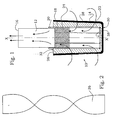
- a filter element 10 according to the invention has a tube 12 and a filter body 14 on.
- the tube 12 and the filter body 14 are preferably cylindrical and arranged concentrically about a longitudinal axis X-X.
- the pipe 12 has a free end 16 and a filter body side end 18.
- a support frame 20 is attached to the The filter body end 18 .
- This can be off Bars 22 are formed, which are covered by a network structure.
- a network structure For example, a grid 24, but also a stocking provided be.
- the support frame 20 is surrounded by a base layer 26, which with the Carrying frame 20 is connected.
- the base layer 26 is again a Outer layer 28 is arranged, which is connected to the base layer.
- Either the base layer 26 as well as the outer layer 28 may be epoxy resin have as binding and connecting means. Starting epoxy resin Any other suitable adhesive or binder may be used, depending after use, however, make sure that this no toxins may secrete.
- the filter body 14 has an end face 30 and a rear side 32.
- the Back side 32 is not in the present embodiment of the outer layer 28 covered, the back 32 can be either impermeable or else also be covered with the outer layer 28.
- the filter body 14 has a slightly conical shape in order to manufacture it easier to remove from its mold.
- the rods 22 are advantageously by transverse bars 34 to the pipe 12 opposite ends connected together.
- the grid 24 is shown only partially in FIG. 1, it extends over the entire length of the bars 22.
- the bars 22 occur in the illustrated embodiment from the back 32 of the filter body 14, also This is only an example to understand, other mounting options for the filter body are conceivable.
- the illustrated arrows illustrate that the liquid from all sides on the outside through the outer layer 28 and the base layer 26 into the cavity penetrate the support frame 20 and are discharged through the pipe 12 can.
- Figure 2 shows a helical flow body 36, which in a particularly advantageous variant in the hollow body of the support structure 20 and in the tube 12 can be used and fastened in these.
- the flow body 36 is connected to an inner bottom 38 of the filter body 14 and has the task to control the fluid swirling divert by diverting into a rectified flow.
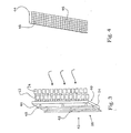
- FIG. 3 illustrates the use of filter elements 10 according to the invention in one embodiment Filter wall 38. This has a front side opposite to the flow 40 and an opposite rear side 42. The flow is back represented by arrows.
- the filter wall 38 consists essentially of a support structure 44th (See also Figure 4), in which the filter elements 10 can be used.
- the Carrying structure 44 can on its back 42 support members 48th have, with which the filter wall are kept in the flowing water can.
- the filter elements 10 are inserted with their tubes 12 in the openings 46 and depending on the application with the help of a thread or Attached to cotter pins.
- the liquid thus flows through the filter body 14 and the tubes 12 therethrough and thus passes from the front 40 to the back 42 of the support structure 44th
- FIG. 3 also illustrates an advantageous embodiment of a filter wall 38 in that filter elements 10 with long tubes 12 and filter elements 10 are provided with shorter tubes 12.
- the filter elements 10 are arranged such that, in principle, two layers result, namely a front and a back layer.
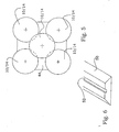
- the filter elements 10 can for Formation of these two layers can be arranged arbitrarily, Figure 5 illustrates but an advantageous arrangement possibility.
- a filter element 10 with a long tube 12 is arranged between four filter elements 10 with short tubes 12 is centrally.
- the filter body 14 of the filter elements 10 with a long tube 12 spaced from the filter bodies 14 of the filter elements 10 may be arranged with short tube 12, but they can also be postponed until contact.
- the support structure 44 can by a cover, not shown here covered on the front side, the cover having circular openings for receiving the tubes 12.
- a cover has the advantage that the filter wall 38 only through the filter elements 10 of the liquid is passable.
- FIG. 6 shows a foot body 50 for receiving the support structure 44.
- the foot 50 has a longitudinal groove 52 into which a lower transverse edge 54 of the support structure 44 is used.
- the foot body 50 will be on the floor or bottom of the aquifer or Flowed on.
- the support members 48 can then be omitted, they but can also remain as additional additional support.
- a significant advantage of the filter wall 38 according to the invention also exists in that the filter elements 10 are quickly and easily serviced or replaced can be.
Landscapes
- Chemical & Material Sciences (AREA)
- Chemical Kinetics & Catalysis (AREA)
- Inorganic Chemistry (AREA)
- Engineering & Computer Science (AREA)
- Ceramic Engineering (AREA)
- Life Sciences & Earth Sciences (AREA)
- Geology (AREA)
- Filtering Materials (AREA)
- Filtration Of Liquid (AREA)
- Separation Using Semi-Permeable Membranes (AREA)
Abstract
Description
- einem Rohr, das verbunden ist mit
- einem hohlen Filterkörper, der gebildet ist aus
- einem innen angeordneten, einen Hohlraum ausbildenden und mit dem Rohr verbundenem Tragegerüst,
- einer Grundschicht aus relativ grobkörnigem Material, dass das Tagegerüst umgibt und mit diesem verbunden ist,
- einer Außenschicht aus relativ feinkörnigem Material, dass die Grundschicht umgibt und mit dieser verbunden ist,
- eine Tragekonstruktion mit einer der Fließrichtung der Flüssigkeit im eingesetzten Zustand entgegen gesetzten Vorderseite und einer Rückseite, und
- Öffnungen in die je ein Rohr eines Filterelementes nach einem der Ansprüche 1 bis 6 einsetzbar ist.
- Fig. 1:
- Ein erfindungsgemäßes Filterelement im Schnitt,
- Fig. 2:
- einen helixförmigen Strömungskörper,
- Fig. 3:
- eine perspektivische Darstellung einer erfindungsgemäßen Filterwand in Seitenansicht,
- Fig. 4:
- eine Tragekonstruktion einer Filterwand,
- Fig. 5:
- eine Prinzipdarstellung der Anordnung von Filterelementen in der Filterwand,
- Fig. 6:
- einen Fußkörper zur Halterung der Filterwand in einem fließendem Gewässer.
Claims (12)
- Längliches Filterelement (10) für das Zurückhalten von Grobstoffen in einer fließenden Flüssigkeit, mitsodass die Flüssigkeit von außen in den Filterkörper (14) und dann durch das Rohr (12) abfließen kann.einem Rohr (12), das verbunden ist miteinem Hohlenfilterkörper (14), der gebildet ist auseinem innen angeordneten, einen Hohlraum ausbildenden und mit dem Rohr (12) verbundenen Tragegerüst (20),einer Grundschicht (26) aus relativ grobkörnigem Material, dass das Tagegerüst (20) umgibt und mit diesem verbunden ist,einer Außenschicht (28) aus relativ feinkörnigem Material, dass die Grundschicht (26) umgibt und mit dieser verbunden ist,
- Längliches Filterelement (10) nach Anspruch 1, dadurch gekennzeichnet, dass die Grundschicht (26) aus Split mit einer Körnung von 3 mm bis 10 mm, vorzugsweise 6 mm bis 8 mm und die Außenschicht aus einem körnigen Material mit einer Körnung von weniger als 2 mm, vorzugsweise 0,3 mm bis 1,3 mm gebildet ist.
- Längliches Filterelement (10) nach Anspruch 1 oder Anspruch 2, dadurch gekennzeichnet, dass das Verhältnis der Schichtdicken der Außenschicht (28) und der Grundschicht (26) etwa 1 zu 3 beträgt.
- Längliches Filterelement (10) nach einem der Ansprüche 1 bis 3, dadurch gekennzeichnet, dass im Hohlraum des Tragegerüstes ein Strömungskörper (36) angeordnet ist, der sich bis in das Rohr (12) erstreckt und turbulente Strömungen der hereinströmenden Flüssigkeit in eine gleichgerichtete Strömung umleitet.
- Längliches Filterelement (10) nach einem der Ansprüche 1 bis 4, dadurch gekennzeichnet, dass das Tragegerüst aus Stäben (22) gebildet ist, die endseitig mit einem freien Ende der Rohres (12) verbunden sind und die von einem Gitternetz (24) umgeben sind.
- Längliches Filterelement (10) nach einem der Ansprüche 1 bis 5, dadurch gekennzeichnet, dass der Filterkörper (14) im wesentlichen zylinderförmig ausgebildet ist.
- Filterwand (38) zum Einsetzen in eine strömende Flüssigkeit, aufweisendeine Tragekonstruktion (44) mit einer der Fließrichtung der Flüssigkeit im eingesetzten Zustand entgegengesetzten Vorderseite (40) und einer Rückseite (42), undÖffnungen (46), in die je ein Rohr (12) eines Filterelementes (10) nach einem der Ansprüche 1 bis 6 einsetzbar ist.
- Filterwand (38) nach Anspruch 7, dadurch gekennzeichnet, dass die Vorderseite (40) durch eine Abdeckung flächig abgedeckt ist, wobei die Abdeckung kreisförmige Öffnungen aufweist, in die jeweils ein Rohr (12) eines Filterelements (10) einsetzbar ist.
- Filterwand (38) nach Anspruch 7 oder 8, dadurch gekennzeichnet, dass in die Öffnungen (46) Filterelemente (10) mit unterschiedlich langen Rohren (12) eingesetzt sind, sodass im Querschnitt der Filterwand (38) eine vordere Schicht Filterkörper (14) und eine hintere Schicht Filterkörper (14) ausgebildet ist.
- Filterwand (38) nach Anspruch 9, dadurch gekennzeichnet, dass die Filterelemente (10) derart angeordnet sind, dass sich jeweils ein langes Rohr (12) zwischen vier Filterkörpern (14) von Filterelementen (10) der hinteren Schicht hindurch in eine Öffnung (46) erstreckt.
- Filterwand (38) nach einem der Ansprüche 7 bis 10, dadurch gekennzeichnet, dass die Filterelemente (10) an der Tragekonstruktion (44) lösbar befestigbar sind.
- Filterwand (38) nach einem der Ansprüche 7 bis 11, dadurch gekennzeichnet, dass ein Fußkörper (50) mit einer Nut (52) vorgesehen ist, in die die Tragekonstruktion (44) mit einer Querkante (54) einstellbar und in dieser gehalten ist.
Applications Claiming Priority (2)
| Application Number | Priority Date | Filing Date | Title |
|---|---|---|---|
| DE10352937A DE10352937B3 (de) | 2003-11-11 | 2003-11-11 | Filterelement für das Zurückhalten von Grobstoffen in einer fließenden Flüssigkeit |
| DE10352937 | 2003-11-11 |
Publications (3)
| Publication Number | Publication Date |
|---|---|
| EP1530992A2 true EP1530992A2 (de) | 2005-05-18 |
| EP1530992A3 EP1530992A3 (de) | 2005-08-03 |
| EP1530992B1 EP1530992B1 (de) | 2007-11-28 |
Family
ID=34428704
Family Applications (1)
| Application Number | Title | Priority Date | Filing Date |
|---|---|---|---|
| EP04022628A Expired - Lifetime EP1530992B1 (de) | 2003-11-11 | 2004-09-23 | Filterelement für das Zurückhalten von Grobstoffen in einer fliessenden Flüssigkeit |
Country Status (2)
| Country | Link |
|---|---|
| EP (1) | EP1530992B1 (de) |
| DE (2) | DE10352937B3 (de) |
Cited By (1)
| Publication number | Priority date | Publication date | Assignee | Title |
|---|---|---|---|---|
| CN113789843A (zh) * | 2021-09-18 | 2021-12-14 | 同济大学建筑设计研究院(集团)有限公司 | 一种用于合流制排渠内的一体化截流装置 |
Citations (3)
| Publication number | Priority date | Publication date | Assignee | Title |
|---|---|---|---|---|
| DE19515924A1 (de) | 1995-05-02 | 1995-10-05 | Umwelttechnik & Anlagenbau Gmb | Feinrechen mit Reinigungseinrichtung |
| DE19714089A1 (de) | 1997-04-07 | 1998-10-08 | Manfred Huetten | Filterstufenrechen |
| DE10100098A1 (de) | 2000-12-07 | 2002-06-13 | Alexander Von Koeckritz | Rechen für wasserbauliche Anlagen |
Family Cites Families (8)
| Publication number | Priority date | Publication date | Assignee | Title |
|---|---|---|---|---|
| GB786570A (en) * | 1955-01-26 | 1957-11-20 | Paterson Engineering Company L | Improved filter for liquids |
| US4629483A (en) * | 1986-01-06 | 1986-12-16 | Refractron Corp. | Ceramic filter with plural layers of different porosity |
| DE3943249C2 (de) * | 1989-12-29 | 1993-11-18 | Seitz Filter Werke | Geschlossenes Filterelement |
| DE4243932C2 (de) * | 1992-12-23 | 1999-06-10 | T Z Entwicklungs & Handelsgese | Schutzgitter für Freispiegelgerinne |
| DE19533935C2 (de) * | 1994-09-20 | 1998-09-24 | Patrick Blaase | Vorrichtung für die Reinigung von Abwasser |
| CN1147210A (zh) * | 1994-12-27 | 1997-04-09 | 有限会社米卡子基文化会馆 | 多孔陶瓷过滤器、其制造方法及多孔陶瓷过滤器制造用挤出成型模具和使用该模具的挤出成型装置 |
| CA2190238A1 (en) * | 1996-07-15 | 1998-01-15 | Ryutaro Motoki | Sintered metal filters |
| GB9825489D0 (en) * | 1998-11-21 | 1999-01-13 | Fairey Microfiltrex Limited | Filter elements |
-
2003
- 2003-11-11 DE DE10352937A patent/DE10352937B3/de not_active Expired - Fee Related
-
2004
- 2004-09-23 EP EP04022628A patent/EP1530992B1/de not_active Expired - Lifetime
- 2004-09-23 DE DE502004005597T patent/DE502004005597D1/de not_active Expired - Lifetime
Patent Citations (3)
| Publication number | Priority date | Publication date | Assignee | Title |
|---|---|---|---|---|
| DE19515924A1 (de) | 1995-05-02 | 1995-10-05 | Umwelttechnik & Anlagenbau Gmb | Feinrechen mit Reinigungseinrichtung |
| DE19714089A1 (de) | 1997-04-07 | 1998-10-08 | Manfred Huetten | Filterstufenrechen |
| DE10100098A1 (de) | 2000-12-07 | 2002-06-13 | Alexander Von Koeckritz | Rechen für wasserbauliche Anlagen |
Cited By (1)
| Publication number | Priority date | Publication date | Assignee | Title |
|---|---|---|---|---|
| CN113789843A (zh) * | 2021-09-18 | 2021-12-14 | 同济大学建筑设计研究院(集团)有限公司 | 一种用于合流制排渠内的一体化截流装置 |
Also Published As
| Publication number | Publication date |
|---|---|
| DE502004005597D1 (de) | 2008-01-10 |
| EP1530992B1 (de) | 2007-11-28 |
| DE10352937B3 (de) | 2005-06-02 |
| EP1530992A3 (de) | 2005-08-03 |
Similar Documents
| Publication | Publication Date | Title |
|---|---|---|
| DE2852108A1 (de) | Rohrbrunnenfilter | |
| DE102010037223B4 (de) | Wasserfassung | |
| DE1246598B (de) | Vorrichtung zum mechanischen und biologischen Klaeren von Abwaessern | |
| EP1530992B1 (de) | Filterelement für das Zurückhalten von Grobstoffen in einer fliessenden Flüssigkeit | |
| AT410453B (de) | Entwässerungssystem | |
| EP1702661B1 (de) | Verfahren zur Wasserreinigung mit einem gestrickten Filter | |
| DE1800852A1 (de) | Filterstrang fuer Rohrbrunnen | |
| DE68902618T2 (de) | Pumpenanlage, insbesondere fuer bewaesserung. | |
| WO2011107514A1 (de) | Selbstnachspannender absolutfilter | |
| EP1038436B1 (de) | Vorrichtung zum Filtern eines Gewässers | |
| DE102013107153A1 (de) | Reinigungsschacht sowie Verfahren zur dezentralen Regenwasserbehandlung | |
| EP1038435B1 (de) | Filtervorrichtung eines Gewässers | |
| Steininger et al. | Jüngeres Tertiär | |
| DE10221968A1 (de) | Aufnahmevorrichtung für Trocknungsmittel | |
| DE9413754U1 (de) | Ansaugfilter für eine Teichpumpe | |
| EP2674531B1 (de) | Staustufe in einem fließenden Gewässer, mit einem künstlichen Auslaufgerinne und einem Fischpass | |
| DE102005019190B4 (de) | Ablaufkörper | |
| DE1911808A1 (de) | Schmutzfilter fuer Fluessigkeitsleitungen,insbesondere Brauchwasserleitungen | |
| DE4024405A1 (de) | Anlage zum be- und/oder entwaessern des bodens | |
| DE2534430C2 (de) | Wasseraufbereitungseinrichtung | |
| DE10100098A1 (de) | Rechen für wasserbauliche Anlagen | |
| DE3400348A1 (de) | Formteil aus beton, keramischen massen od. dgl. | |
| DE1969143U (de) | Filtriervorrichtung. | |
| EP3805474B1 (de) | Wirbeldrosselvorrichtung | |
| AT280168B (de) | Drainageeinrichtung |
Legal Events
| Date | Code | Title | Description |
|---|---|---|---|
| PUAI | Public reference made under article 153(3) epc to a published international application that has entered the european phase |
Free format text: ORIGINAL CODE: 0009012 |
|
| AK | Designated contracting states |
Kind code of ref document: A2 Designated state(s): AT BE BG CH CY CZ DE DK EE ES FI FR GB GR HU IE IT LI LU MC NL PL PT RO SE SI SK TR |
|
| AX | Request for extension of the european patent |
Extension state: AL HR LT LV MK |
|
| PUAL | Search report despatched |
Free format text: ORIGINAL CODE: 0009013 |
|
| AK | Designated contracting states |
Kind code of ref document: A3 Designated state(s): AT BE BG CH CY CZ DE DK EE ES FI FR GB GR HU IE IT LI LU MC NL PL PT RO SE SI SK TR |
|
| AX | Request for extension of the european patent |
Extension state: AL HR LT LV MK |
|
| 17P | Request for examination filed |
Effective date: 20060203 |
|
| AKX | Designation fees paid |
Designated state(s): AT BE BG CH CY CZ DE DK EE ES FI FR GB GR HU IE IT LI LU MC NL PL PT RO SE SI SK TR |
|
| 17Q | First examination report despatched |
Effective date: 20060712 |
|
| GRAP | Despatch of communication of intention to grant a patent |
Free format text: ORIGINAL CODE: EPIDOSNIGR1 |
|
| GRAS | Grant fee paid |
Free format text: ORIGINAL CODE: EPIDOSNIGR3 |
|
| GRAA | (expected) grant |
Free format text: ORIGINAL CODE: 0009210 |
|
| AK | Designated contracting states |
Kind code of ref document: B1 Designated state(s): AT BE BG CH CY CZ DE DK EE ES FI FR GB GR HU IE IT LI LU MC NL PL PT RO SE SI SK TR |
|
| REG | Reference to a national code |
Ref country code: GB Ref legal event code: FG4D Free format text: NOT ENGLISH |
|
| REG | Reference to a national code |
Ref country code: IE Ref legal event code: FG4D Free format text: LANGUAGE OF EP DOCUMENT: GERMAN |
|
| REG | Reference to a national code |
Ref country code: CH Ref legal event code: EP |
|
| REF | Corresponds to: |
Ref document number: 502004005597 Country of ref document: DE Date of ref document: 20080110 Kind code of ref document: P |
|
| RAP2 | Party data changed (patent owner data changed or rights of a patent transferred) |
Owner name: BLOMEIER, MAXIMILIAN |
|
| RIN2 | Information on inventor provided after grant (corrected) |
Inventor name: BLOMEIER, MAXIMILIAN |
|
| NLT2 | Nl: modifications (of names), taken from the european patent patent bulletin |
Owner name: BLOMEIER, MAXIMILIAN Effective date: 20080213 |
|
| PG25 | Lapsed in a contracting state [announced via postgrant information from national office to epo] |
Ref country code: ES Free format text: LAPSE BECAUSE OF FAILURE TO SUBMIT A TRANSLATION OF THE DESCRIPTION OR TO PAY THE FEE WITHIN THE PRESCRIBED TIME-LIMIT Effective date: 20080311 Ref country code: SE Free format text: LAPSE BECAUSE OF FAILURE TO SUBMIT A TRANSLATION OF THE DESCRIPTION OR TO PAY THE FEE WITHIN THE PRESCRIBED TIME-LIMIT Effective date: 20080228 Ref country code: NL Free format text: LAPSE BECAUSE OF FAILURE TO SUBMIT A TRANSLATION OF THE DESCRIPTION OR TO PAY THE FEE WITHIN THE PRESCRIBED TIME-LIMIT Effective date: 20071128 |
|
| NLV1 | Nl: lapsed or annulled due to failure to fulfill the requirements of art. 29p and 29m of the patents act | ||
| PG25 | Lapsed in a contracting state [announced via postgrant information from national office to epo] |
Ref country code: SI Free format text: LAPSE BECAUSE OF FAILURE TO SUBMIT A TRANSLATION OF THE DESCRIPTION OR TO PAY THE FEE WITHIN THE PRESCRIBED TIME-LIMIT Effective date: 20071128 Ref country code: FI Free format text: LAPSE BECAUSE OF FAILURE TO SUBMIT A TRANSLATION OF THE DESCRIPTION OR TO PAY THE FEE WITHIN THE PRESCRIBED TIME-LIMIT Effective date: 20071128 Ref country code: BG Free format text: LAPSE BECAUSE OF FAILURE TO SUBMIT A TRANSLATION OF THE DESCRIPTION OR TO PAY THE FEE WITHIN THE PRESCRIBED TIME-LIMIT Effective date: 20080228 Ref country code: PL Free format text: LAPSE BECAUSE OF FAILURE TO SUBMIT A TRANSLATION OF THE DESCRIPTION OR TO PAY THE FEE WITHIN THE PRESCRIBED TIME-LIMIT Effective date: 20071128 |
|
| PG25 | Lapsed in a contracting state [announced via postgrant information from national office to epo] |
Ref country code: DK Free format text: LAPSE BECAUSE OF FAILURE TO SUBMIT A TRANSLATION OF THE DESCRIPTION OR TO PAY THE FEE WITHIN THE PRESCRIBED TIME-LIMIT Effective date: 20071128 Ref country code: CZ Free format text: LAPSE BECAUSE OF FAILURE TO SUBMIT A TRANSLATION OF THE DESCRIPTION OR TO PAY THE FEE WITHIN THE PRESCRIBED TIME-LIMIT Effective date: 20071128 |
|
| PG25 | Lapsed in a contracting state [announced via postgrant information from national office to epo] |
Ref country code: SK Free format text: LAPSE BECAUSE OF FAILURE TO SUBMIT A TRANSLATION OF THE DESCRIPTION OR TO PAY THE FEE WITHIN THE PRESCRIBED TIME-LIMIT Effective date: 20071128 Ref country code: RO Free format text: LAPSE BECAUSE OF FAILURE TO SUBMIT A TRANSLATION OF THE DESCRIPTION OR TO PAY THE FEE WITHIN THE PRESCRIBED TIME-LIMIT Effective date: 20071128 |
|
| EN | Fr: translation not filed | ||
| PG25 | Lapsed in a contracting state [announced via postgrant information from national office to epo] |
Ref country code: PT Free format text: LAPSE BECAUSE OF FAILURE TO SUBMIT A TRANSLATION OF THE DESCRIPTION OR TO PAY THE FEE WITHIN THE PRESCRIBED TIME-LIMIT Effective date: 20080428 |
|
| REG | Reference to a national code |
Ref country code: IE Ref legal event code: FD4D |
|
| PLBE | No opposition filed within time limit |
Free format text: ORIGINAL CODE: 0009261 |
|
| STAA | Information on the status of an ep patent application or granted ep patent |
Free format text: STATUS: NO OPPOSITION FILED WITHIN TIME LIMIT |
|
| PG25 | Lapsed in a contracting state [announced via postgrant information from national office to epo] |
Ref country code: IE Free format text: LAPSE BECAUSE OF FAILURE TO SUBMIT A TRANSLATION OF THE DESCRIPTION OR TO PAY THE FEE WITHIN THE PRESCRIBED TIME-LIMIT Effective date: 20071128 Ref country code: FR Free format text: LAPSE BECAUSE OF FAILURE TO SUBMIT A TRANSLATION OF THE DESCRIPTION OR TO PAY THE FEE WITHIN THE PRESCRIBED TIME-LIMIT Effective date: 20080912 |
|
| REG | Reference to a national code |
Ref country code: FR Ref legal event code: RN |
|
| 26N | No opposition filed |
Effective date: 20080829 |
|
| REG | Reference to a national code |
Ref country code: FR Ref legal event code: FC |
|
| ET | Fr: translation filed | ||
| PG25 | Lapsed in a contracting state [announced via postgrant information from national office to epo] |
Ref country code: GR Free format text: LAPSE BECAUSE OF FAILURE TO SUBMIT A TRANSLATION OF THE DESCRIPTION OR TO PAY THE FEE WITHIN THE PRESCRIBED TIME-LIMIT Effective date: 20080229 |
|
| BERE | Be: lapsed |
Owner name: BLOMEIER, MAXIMILIAN Effective date: 20080930 Owner name: LULSDORF, DETLEF Effective date: 20080930 Owner name: SAUER, MARKUS Effective date: 20080930 Owner name: WILHELMY, KARL-HEINZ Effective date: 20080930 |
|
| PG25 | Lapsed in a contracting state [announced via postgrant information from national office to epo] |
Ref country code: EE Free format text: LAPSE BECAUSE OF FAILURE TO SUBMIT A TRANSLATION OF THE DESCRIPTION OR TO PAY THE FEE WITHIN THE PRESCRIBED TIME-LIMIT Effective date: 20071128 Ref country code: MC Free format text: LAPSE BECAUSE OF NON-PAYMENT OF DUE FEES Effective date: 20080930 |
|
| REG | Reference to a national code |
Ref country code: CH Ref legal event code: PL |
|
| PG25 | Lapsed in a contracting state [announced via postgrant information from national office to epo] |
Ref country code: BE Free format text: LAPSE BECAUSE OF NON-PAYMENT OF DUE FEES Effective date: 20080930 Ref country code: CY Free format text: LAPSE BECAUSE OF FAILURE TO SUBMIT A TRANSLATION OF THE DESCRIPTION OR TO PAY THE FEE WITHIN THE PRESCRIBED TIME-LIMIT Effective date: 20071128 |
|
| PG25 | Lapsed in a contracting state [announced via postgrant information from national office to epo] |
Ref country code: IT Free format text: LAPSE BECAUSE OF NON-PAYMENT OF DUE FEES Effective date: 20080923 |
|
| PG25 | Lapsed in a contracting state [announced via postgrant information from national office to epo] |
Ref country code: AT Free format text: LAPSE BECAUSE OF NON-PAYMENT OF DUE FEES Effective date: 20080923 Ref country code: LI Free format text: LAPSE BECAUSE OF NON-PAYMENT OF DUE FEES Effective date: 20080930 Ref country code: CH Free format text: LAPSE BECAUSE OF NON-PAYMENT OF DUE FEES Effective date: 20080930 |
|
| PG25 | Lapsed in a contracting state [announced via postgrant information from national office to epo] |
Ref country code: HU Free format text: LAPSE BECAUSE OF FAILURE TO SUBMIT A TRANSLATION OF THE DESCRIPTION OR TO PAY THE FEE WITHIN THE PRESCRIBED TIME-LIMIT Effective date: 20080529 Ref country code: LU Free format text: LAPSE BECAUSE OF NON-PAYMENT OF DUE FEES Effective date: 20080923 |
|
| PG25 | Lapsed in a contracting state [announced via postgrant information from national office to epo] |
Ref country code: TR Free format text: LAPSE BECAUSE OF FAILURE TO SUBMIT A TRANSLATION OF THE DESCRIPTION OR TO PAY THE FEE WITHIN THE PRESCRIBED TIME-LIMIT Effective date: 20071128 |
|
| PGFP | Annual fee paid to national office [announced via postgrant information from national office to epo] |
Ref country code: FR Payment date: 20111005 Year of fee payment: 8 Ref country code: GB Payment date: 20110923 Year of fee payment: 8 |
|
| GBPC | Gb: european patent ceased through non-payment of renewal fee |
Effective date: 20120923 |
|
| REG | Reference to a national code |
Ref country code: FR Ref legal event code: ST Effective date: 20130531 |
|
| PG25 | Lapsed in a contracting state [announced via postgrant information from national office to epo] |
Ref country code: GB Free format text: LAPSE BECAUSE OF NON-PAYMENT OF DUE FEES Effective date: 20120923 |
|
| PG25 | Lapsed in a contracting state [announced via postgrant information from national office to epo] |
Ref country code: FR Free format text: LAPSE BECAUSE OF NON-PAYMENT OF DUE FEES Effective date: 20121001 |
|
| PGFP | Annual fee paid to national office [announced via postgrant information from national office to epo] |
Ref country code: DE Payment date: 20150216 Year of fee payment: 11 |
|
| REG | Reference to a national code |
Ref country code: DE Ref legal event code: R119 Ref document number: 502004005597 Country of ref document: DE |
|
| PG25 | Lapsed in a contracting state [announced via postgrant information from national office to epo] |
Ref country code: DE Free format text: LAPSE BECAUSE OF NON-PAYMENT OF DUE FEES Effective date: 20160401 |