EP1530682B2 - Roue de ventilateur pourvue d'une separation de graisse integree et destinee notamment a un appareil de cuisson - Google Patents
Roue de ventilateur pourvue d'une separation de graisse integree et destinee notamment a un appareil de cuisson Download PDFInfo
- Publication number
- EP1530682B2 EP1530682B2 EP20030790684 EP03790684A EP1530682B2 EP 1530682 B2 EP1530682 B2 EP 1530682B2 EP 20030790684 EP20030790684 EP 20030790684 EP 03790684 A EP03790684 A EP 03790684A EP 1530682 B2 EP1530682 B2 EP 1530682B2
- Authority
- EP
- European Patent Office
- Prior art keywords
- fan impeller
- cooking
- elevation
- fan
- regions
- Prior art date
- Legal status (The legal status is an assumption and is not a legal conclusion. Google has not performed a legal analysis and makes no representation as to the accuracy of the status listed.)
- Expired - Lifetime
Links
- 238000010411 cooking Methods 0.000 title claims description 29
- 239000002245 particle Substances 0.000 title description 24
- 238000001556 precipitation Methods 0.000 title 1
- 229920001296 polysiloxane Polymers 0.000 claims description 2
- 238000005452 bending Methods 0.000 claims 1
- 239000007788 liquid Substances 0.000 description 18
- 239000007787 solid Substances 0.000 description 18
- 238000010438 heat treatment Methods 0.000 description 3
- 230000000694 effects Effects 0.000 description 2
- 230000008021 deposition Effects 0.000 description 1
- 239000002932 luster Substances 0.000 description 1
- 238000000034 method Methods 0.000 description 1
- 230000006641 stabilisation Effects 0.000 description 1
- 238000011105 stabilization Methods 0.000 description 1
Images
Classifications
-
- F—MECHANICAL ENGINEERING; LIGHTING; HEATING; WEAPONS; BLASTING
- F04—POSITIVE - DISPLACEMENT MACHINES FOR LIQUIDS; PUMPS FOR LIQUIDS OR ELASTIC FLUIDS
- F04D—NON-POSITIVE-DISPLACEMENT PUMPS
- F04D29/00—Details, component parts, or accessories
- F04D29/26—Rotors specially for elastic fluids
- F04D29/28—Rotors specially for elastic fluids for centrifugal or helico-centrifugal pumps for radial-flow or helico-centrifugal pumps
- F04D29/289—Rotors specially for elastic fluids for centrifugal or helico-centrifugal pumps for radial-flow or helico-centrifugal pumps having provision against erosion or for dust-separation
-
- F—MECHANICAL ENGINEERING; LIGHTING; HEATING; WEAPONS; BLASTING
- F04—POSITIVE - DISPLACEMENT MACHINES FOR LIQUIDS; PUMPS FOR LIQUIDS OR ELASTIC FLUIDS
- F04D—NON-POSITIVE-DISPLACEMENT PUMPS
- F04D23/00—Other rotary non-positive-displacement pumps
- F04D23/001—Pumps adapted for conveying materials or for handling specific elastic fluids
-
- F—MECHANICAL ENGINEERING; LIGHTING; HEATING; WEAPONS; BLASTING
- F04—POSITIVE - DISPLACEMENT MACHINES FOR LIQUIDS; PUMPS FOR LIQUIDS OR ELASTIC FLUIDS
- F04D—NON-POSITIVE-DISPLACEMENT PUMPS
- F04D29/00—Details, component parts, or accessories
- F04D29/26—Rotors specially for elastic fluids
- F04D29/28—Rotors specially for elastic fluids for centrifugal or helico-centrifugal pumps for radial-flow or helico-centrifugal pumps
- F04D29/281—Rotors specially for elastic fluids for centrifugal or helico-centrifugal pumps for radial-flow or helico-centrifugal pumps for fans or blowers
-
- F—MECHANICAL ENGINEERING; LIGHTING; HEATING; WEAPONS; BLASTING
- F04—POSITIVE - DISPLACEMENT MACHINES FOR LIQUIDS; PUMPS FOR LIQUIDS OR ELASTIC FLUIDS
- F04D—NON-POSITIVE-DISPLACEMENT PUMPS
- F04D29/00—Details, component parts, or accessories
- F04D29/26—Rotors specially for elastic fluids
- F04D29/28—Rotors specially for elastic fluids for centrifugal or helico-centrifugal pumps for radial-flow or helico-centrifugal pumps
- F04D29/30—Vanes
Definitions
- the present invention relates to a cooking appliance fan according to the preamble of claim 1.
- Fan wheels are well known in the art and typically serve to circulate air. Fan wheels are known in a variety of forms, for example, fan wheels are known with propeller-like wings or with blade-like wings.
- One problem with fan wheels known in the art is that particulates and / or liquid particles present in the recirculated air may deposit on the blades of the fan wheel, resulting in fouling of the fan wheel. It can also come through the known fan wheels to an undesirable distribution of the solid and / or liquid particles.
- the fan wheel is arranged in a cooking appliance mostly in a separate from the cooking chamber via a baffle fan space, sucks air from the cooking chamber and directs them radially to the surrounding walls, so as an air flow within the cooking appliance, from the cooking chamber in the fan room and back to the cooking chamber, to produce.
- Concentric around the fan around a heater or a heat exchanger is often arranged so that circulating air is also passed to this heater or this heat exchanger to be heated.
- fat particles present within the circulated air can be conducted to, for example, the heating device, where they can be burned, which can lead to a reduction in the quality of the food and to an odor nuisance.
- This problem arises in particular when the air within the cooking appliance is permanently circulated through the fan, in which case the solid and / or liquid particles are constantly held in the gas volume by the circulating air flow.
- a device which comprises an impact surface or a separating ring around the fan wheel, onto which or onto which a gas stream prevailing in the gas volume occurs, wherein the solid and / or liquid particles deposit on impact at least partially and can run to a first discharge area.
- a fan with a number of radially arranged blades which project substantially in parallel to the axis of rotation of the fan from a housing wall of the cooking chamber facing support disc or base plate, known in which at least between some of the blades near the support disk, but at a distance from this , Baffles are arranged, the radially outer outer edge substantially aligned with the outer circumference of the fan wheel, the radially inner inner edges spaced from the axis of rotation of the fan and with the support disk and the respective adjacent two blades each have a nozzle device for generating a radially outward directed gas flow near the support disk.
- a fan is known in which on the outer surface of at least a portion of the fan blades at least one elevation is arranged, which extends away from the base plate.
- Object of the present invention is therefore to develop the generic fan to the effect that the disadvantages of the prior art are overcome.
- it is intended to prevent solids and / or liquid particles present in a circulating air in a cooking appliance from passing directly through the fan wheel onto a heating device or heat exchanger surrounding the fan wheel, without the efficiency of the fan wheel being significantly reduced.
- the present invention is based on the surprising finding that is avoided by elevations on the outer surfaces of fan blades on a base plate on the one hand that contained in circulating air solids and / or liquid particles, in particular in the form of fat particles are deflected directly radially by the fan , Rather, solid and / or liquid particles impinging on the outer surfaces of the fan blades are stopped at the elevation and diverted by the particular geometry of the elevation toward the baseplate. In the area of the base plate, the Solid and / or liquid particles are then discharged from the fan blades, without hitting devices that are arranged immediately radially around the fan, such as a heater within a cooking appliance.
- the fan according to the invention in a surprising manner that the efficiency of the fan is not significantly affected, since no major obstacles in the radial flow of the circulating air are arranged. Further, the elevations disposed on the outsides of the luster wheel blades can provide additional stability to the fan blades themselves.
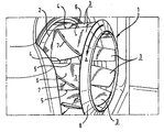
- FIG. 1 shows a perspective view of a fan according to the invention.
- the figure shows a perspective view of an inventive fan 1, which is installed in a fan room of a cooking appliance partially shown to rotate in the direction of arrow A rotating air in the cooking chamber, which is partially separated from the fan room by a not shown air deflector.
- the fan wheel 1 has a base plate 2 on which a plurality of fan blades 3 are arranged, which face the cooking chamber of the cooking appliance.
- the Lüfterradschaufeln 3 are curved and arranged substantially perpendicular to the base plate 2 to form a substantially radial arrangement on the base plate 2.
- Each fan blade 3 has a trailing edge 5 contacting the air to be circulated first during operation, and an outer surface 6 arranged on the pressure side of the fan wheel 1 during operation.
- an elevation 7 is provided, which extends away from the base plate 2, substantially diagonally from a front edge 4 to the trailing edge 5 of the Lüfterradschaufel 3.
- the elevation 7 is arranged at a distance of 10 to 20 mm from the base plate 2 on the outer surface 6.
- the elevation 7 may extend completely over the entire width of the Lüfterradschaufel 3, or have a distance from the base plate 2 opposite side of the Lüfterradschaufel 3, said distance is preferably 5 to 15 mm.
- a cover ring 8 is provided which provides additional stabilization of the fan blades 3 within the fan 1.
- the elevation 7 should stand out from the outer surface 6 of the Lüfterradschaufel 3 by 2 to 5 mm and end at the end facing the air flow on the trailing edge 5 of the Lüfterradschaufel 3 with a sharp edge to a gutter for impinging solid and / or liquid particles form, which prevents further flow of the solid and / or liquid particles beyond the elevation 7, but causes a guiding in the direction of the base plate 2.
- a seal may be provided on the side lying in the flow shadow between the outer surface 6 and elevation 7.
- This seal may be made, for example, with silicone, but any other seal may be provided which would be obvious to those skilled in the art.
- the fan 1 is rotated in the fan chamber via an engine, not shown in the figure in the direction of arrow A and thus sucks air from the cooking chamber via a central opening in the air baffle centrally and directs them radially outwards, so that they outside of the fan room passes through the baffle again in the cooking chamber.
- Solid and / or liquid particles in particular fat particles of different sizes, which reach in the area of the fan wheel 1, impact on the outer surfaces 6 of the fan blades 3, on the pressure side of the fan wheel, and are discharged along the elevation 7 in the direction of the base plate 2 , If the solids and / or liquid particles reach the end region of the elevation 7 at the front edge 4 of the fan blade 3 (and finally the base plate 2), then the solid and / or liquid particles then released can not directly contact a device radially surrounding the fan wheel 1, such as in the form of a heater, not shown, or a heat exchanger, not shown, are discharged.
- a device radially surrounding the fan wheel 1 such as in the form of a heater, not shown, or a heat exchanger, not shown
- the impeller according to the invention in a cooking appliance thus prevents solids and / or liquid particles from being deposited directly on a heating device surrounding the impeller 1, and also ensures that air circulated by the impeller 1 can be diverted substantially completely radially, since the Efficiency of the fan 1 is only slightly reduced by the increase 7.
- the fan 1 is replaced by the elevations 7 itself a higher stability.
Landscapes
- Engineering & Computer Science (AREA)
- Mechanical Engineering (AREA)
- General Engineering & Computer Science (AREA)
- Structures Of Non-Positive Displacement Pumps (AREA)
Claims (15)
- Roue de ventilateur d'appareil de cuisson (1) située dans une chambre de ventilateur d'un appareil de cuisson, qui est séparée de la chambre de cuisson de l'appareil de cuisson, au moins par zones, via un déflecteur d'air de telle sorte que pendant le fonctionnement de la roue de ventilateur (1), celle-ci va être entraînée en rotation par l'intermédiaire d'un moteur situé dans la chambre de ventilateur, et par conséquent l'air sortant de la chambre de cuisson est aspiré de manière centrale via une ouverture située au milieu du déflecteur d'air, et est détourné radialement vers l'extérieur, de sorte que l'air sortant de la chambre de ventilateur vers l'extérieur revient dans la chambre de cuisson au niveau du déflecteur d'air, dans lequel la roue de ventilateur (1) est dotée d'une plaque de base (2) et d'une pluralité d'aubes de roue de ventilateur (3) fixées sur la plaque de base (2), les aubes de roue de ventilateur (3) sont disposées sensiblement perpendiculairement sur la plaque de base (2), et forment un agencement sensiblement radial, et chaque aube de roue de ventilateur (3) présentant un bord d'attaque (4), disposé radialement extérieurement et sensiblement perpendiculairement à la plaque de base (2), un bord de fuite (5) disposé radialement intérieurement et sensiblement perpendiculairement à la plaque de base (2), une face extérieure (6) disposée sur le côté pression de la roue de ventilateur (1), et une face intérieure disposée sur le côté aspiration de la roue de ventilateur (1), caractérisée en ce que, sur la face extérieure (6) d'au moins une partie des aubes de roue de ventilateur (3), est disposé et/ou réalisé au moins un relief (7), qui est réalisé espacé de la plaque de base (2), et s'écartant de la plaque de base (2), s'étendant sensiblement en diagonale, du bord d'attaque (2) vers le bord de fuite (5) des aubes de roue de ventilateur (3), et un organe d'appui (8) des aubes de roue de ventilateur (3) est prévu, sur la face des aubes de roue de ventilateur (3) opposée à la plaque de base (2).
- Roue de ventilateur d'appareil de cuisson selon la revendication 1, caractérisée en ce que le relief (7) est réalisé sous la forme d'un étagement et/ou est réalisé dans la face extérieure (6).
- Roue de ventilateur d'appareil de cuisson selon la revendication 1 ou 2, caractérisée en ce que les aubes de roue de ventilateur (3) sont incurvées de manière que la face extérieure (6) soit courbée radialement vers l'extérieur, entre le bord d'attaque (4) et le bord de fuite (5).
- Roue de ventilateur d'appareil de cuisson selon l'une quelconque des revendications précédentes, caractérisée en ce qu'au moins un relief (7) présente, au moins par zones, une hauteur d'environ 1 à 10 mm, de préférence de 2 à 4 mm.
- Roue de ventilateur d'appareil de cuisson selon l'une quelconque des revendications précédentes, caractérisée en ce qu'au moins un relief (7) présente, au moins par zones, une largeur de 1 à 10 mm, de préférence de 2 à 4 mm.
- Roue de ventilateur d'appareil de cuisson selon l'une quelconque des revendications précédentes, caractérisée en ce que l'espacement au moins d'un relief (7) par rapport à la plaque de base (2) est, au moins par zones, en particulier dans la zone du bord d'attaque (4), au moins d'environ 5 à 25 mm, de préférence de 10 à 20 mm.
- Roue de ventilateur d'appareil de cuisson selon l'une quelconque des revendications précédentes, caractérisée par un organe d'appui (8), réalisé sous la forme d'une bague de couverture.
- Roue de ventilateur d'appareil de cuisson selon l'une quelconque des revendications précédentes, caractérisée en ce qu'au moins un relief (7) est réalisé, au moins par zones, avec une forme arquée, sachant que, de préférence, il s'incurve en s'écartant de l'organe d'appui (8), en évoluant du bord de fuite (5) respectif vers le bord d'attaque (4) respectif.
- Roue de ventilateur d'appareil de cuisson selon l'une quelconque des revendications précédentes, caractérisée en ce qu'au moins un relief (7) touche avec un angle de 45° à 90° le bord d'attaque (4), de préférence avec un angle de 70° à 90°.
- Roue de ventilateur d'appareil de cuisson selon l'une quelconque des revendications précédentes, caractérisée en ce qu'au moins un relief (7) présente, au moins par zones, un espacement par rapport à l'organe d'appui (8), en particulier dans la zone du bord de fuite (5), d'une valeur d'au moins environ 1 à 10 mm, de préférence de 5 à 15 mm.
- Roue de ventilateur d'appareil de cuisson selon l'une des revendications précédentes, caractérisée en ce qu'au moins un relief (7) est réalisé au moyen d'au moins un fil.
- Roue de ventilateur d'appareil de cuisson selon l'une quelconque des revendications précédentes, caractérisée en ce qu'au moins un relief (7) est rapporté par soudage, au moins par zones, sur la face extérieure (6) des aubes de roue de ventilateur (3).
- Roue de ventilateur d'appareil de cuisson selon l'une quelconque des revendications précédentes, caractérisée en ce que, sur la face extérieure (6) au moins d'une des aubes de roue de ventilateur (3), de préférence de chaque aube de roue de ventilateur (3), dans la zone de fixation entre le relief (7) respectif et la face extérieure (6), est réalisée, au moins par zones, une arête accentuée telle qu'à la forme d'une goulotte, sur le côté situé dans le sens de rotation de la roue de ventilateur.
- Roue de ventilateur d'appareil de cuisson selon l'une quelconque des revendications précédentes, caractérisée en ce qu'au moins un relief (7) présente, au moins par zones, une section transversale profilée, de préférence est incurvé, sachant que, en particulier, le foyer de la courbure est situé sur le côté tourné vers le bord de fuite (5) du relief (7), et/ou présente au moins une rainure, de préférence sur le côté tourné vers le bord de fuite (5).
- Roue de ventilateur d'appareil de cuisson selon l'une des revendications précédentes, caractérisée en ce qu'au moins un relief (7), sur le côté opposé au sens de rotation de la roue de ventilateur (1), est jointoyé de façon étanche, au moins par zones, avec la surface extérieure (6), de préférence avec du silicone.
Applications Claiming Priority (3)
| Application Number | Priority Date | Filing Date | Title |
|---|---|---|---|
| DE10239246 | 2002-08-22 | ||
| DE10239246A DE10239246C1 (de) | 2002-08-22 | 2002-08-22 | Lüfterrad mit integrierter Fettabscheidung, insbesondere für ein Gargerät |
| PCT/DE2003/002640 WO2004020837A1 (fr) | 2002-08-22 | 2003-08-06 | Roue de ventilateur pourvue d'une separation de graisse integree et destinee notamment a un appareil de cuisson |
Publications (3)
| Publication Number | Publication Date |
|---|---|
| EP1530682A1 EP1530682A1 (fr) | 2005-05-18 |
| EP1530682B1 EP1530682B1 (fr) | 2006-05-31 |
| EP1530682B2 true EP1530682B2 (fr) | 2015-04-15 |
Family
ID=27618865
Family Applications (1)
| Application Number | Title | Priority Date | Filing Date |
|---|---|---|---|
| EP20030790684 Expired - Lifetime EP1530682B2 (fr) | 2002-08-22 | 2003-08-06 | Roue de ventilateur pourvue d'une separation de graisse integree et destinee notamment a un appareil de cuisson |
Country Status (5)
| Country | Link |
|---|---|
| US (1) | US7165942B2 (fr) |
| EP (1) | EP1530682B2 (fr) |
| JP (1) | JP4255912B2 (fr) |
| DE (2) | DE10239246C1 (fr) |
| WO (1) | WO2004020837A1 (fr) |
Families Citing this family (16)
| Publication number | Priority date | Publication date | Assignee | Title |
|---|---|---|---|---|
| DE10239246C1 (de) | 2002-08-22 | 2003-08-21 | Rational Ag | Lüfterrad mit integrierter Fettabscheidung, insbesondere für ein Gargerät |
| DE10315341C5 (de) * | 2003-04-03 | 2009-07-30 | Mkn Maschinenfabrik Kurt Neubauer Gmbh & Co. | Gargerät mit einem Gebläse mit Radialgebläserad und Abscheideelement |
| US7112043B2 (en) * | 2003-08-29 | 2006-09-26 | General Motors Corporation | Compressor impeller thickness profile with localized thick spot |
| EP1961966A1 (fr) * | 2007-02-26 | 2008-08-27 | Josip Pavetic | Roue de ventilateur radiale |
| EP1961968A1 (fr) | 2007-02-26 | 2008-08-27 | Josip Pavetic | Roue de ventilateur radial et ventilateur radial équipé de celle-ci doté d'une protection contre la fermeture |
| EP1961969A3 (fr) | 2007-02-26 | 2009-10-21 | Josip Pavetic | Roue de ventilateur radiale |
| EP1961967A1 (fr) * | 2007-02-26 | 2008-08-27 | Josip Pavetic | Roue de ventilateur radial et ventilateur radial équipé de celle-ci |
| EP2143958A1 (fr) * | 2008-07-07 | 2010-01-13 | Josip Pavetic | Ventilateur installé dans un tuyau |
| EP2284401B1 (fr) | 2009-08-11 | 2013-01-30 | Rational AG | Roue de ventilateur et appareil de cuisson |
| RU2522015C2 (ru) * | 2009-10-27 | 2014-07-10 | Дженерал Электрик Компани | Каплеуловитель для центробежного компрессора |
| EP2372163B1 (fr) | 2010-04-01 | 2014-10-08 | Convotherm Elektrogeräte GmbH | Roue de ventilateur |
| ITUB20152807A1 (it) * | 2015-08-03 | 2017-02-03 | Ma Ti Ka S R L | Ventola per forni per la cottura di alimenti |
| DE102016212162A1 (de) * | 2016-07-04 | 2018-01-04 | Convotherm-Elektrogeräte Gmbh | Gewerbliches Gargerät |
| WO2018158226A1 (fr) | 2017-03-03 | 2018-09-07 | Convotherm-Elektrogeräte Gmbh | Roue de ventilateur |
| DE102017203526B4 (de) | 2017-03-03 | 2026-03-05 | Welbilt Deutschland GmbH | Lüfterrad |
| DE102017203539A1 (de) | 2017-03-03 | 2018-09-06 | Convotherm-Elektrogeräte Gmbh | Lüfterrad |
Citations (1)
| Publication number | Priority date | Publication date | Assignee | Title |
|---|---|---|---|---|
| DE3814721A1 (de) † | 1988-04-30 | 1989-11-09 | Asea Brown Boveri | Radialluefter mit integriertem schmutzabscheider |
Family Cites Families (11)
| Publication number | Priority date | Publication date | Assignee | Title |
|---|---|---|---|---|
| US262642A (en) * | 1882-08-15 | Fan-blower | ||
| US168345A (en) * | 1875-10-05 | Improvement in car-couplings | ||
| US1688345A (en) | 1927-08-16 | 1928-10-23 | Buffalo Hammer Mill Corp | Centrifugal fan |
| DE729947C (de) * | 1937-02-09 | 1943-01-05 | Danneberg & Quandt Alleiniger | Geblaeselaufrad |
| US2616764A (en) * | 1948-05-22 | 1952-11-04 | Earl M Parrish | Wear resistant blower surface |
| FR2588925A1 (fr) * | 1985-10-23 | 1987-04-24 | Etri Sa | Ventilateur equipe de moyens pour reduire le bruit engendre par la rotation de ses pales |
| FR2606465B1 (fr) * | 1986-11-06 | 1989-01-13 | Ducellier & Cie | Ventilateur de machine electrique tournante |
| DE4206846C2 (de) * | 1992-03-04 | 1995-11-16 | Rational Gmbh | Vorrichtung zum Abscheiden von Feststoff- und/oder Flüssigkeitspartikeln aus einem Gasvolumen |
| DE4220960A1 (de) * | 1992-06-25 | 1994-01-05 | Turbowerke Meisen Ventilatoren | Schaufeln für Arbeitsmaschinen |
| DE4307405C1 (de) | 1993-03-09 | 1994-11-17 | Rational Gmbh | Lüfterrad |
| DE10239246C1 (de) | 2002-08-22 | 2003-08-21 | Rational Ag | Lüfterrad mit integrierter Fettabscheidung, insbesondere für ein Gargerät |
-
2002
- 2002-08-22 DE DE10239246A patent/DE10239246C1/de not_active Expired - Fee Related
-
2003
- 2003-08-06 EP EP20030790684 patent/EP1530682B2/fr not_active Expired - Lifetime
- 2003-08-06 JP JP2004531451A patent/JP4255912B2/ja not_active Expired - Lifetime
- 2003-08-06 US US10/525,192 patent/US7165942B2/en not_active Expired - Lifetime
- 2003-08-06 DE DE50303600T patent/DE50303600D1/de not_active Expired - Lifetime
- 2003-08-06 WO PCT/DE2003/002640 patent/WO2004020837A1/fr not_active Ceased
Patent Citations (1)
| Publication number | Priority date | Publication date | Assignee | Title |
|---|---|---|---|---|
| DE3814721A1 (de) † | 1988-04-30 | 1989-11-09 | Asea Brown Boveri | Radialluefter mit integriertem schmutzabscheider |
Also Published As
| Publication number | Publication date |
|---|---|
| EP1530682B1 (fr) | 2006-05-31 |
| DE50303600D1 (de) | 2006-07-06 |
| DE10239246C1 (de) | 2003-08-21 |
| US20060165528A1 (en) | 2006-07-27 |
| JP4255912B2 (ja) | 2009-04-22 |
| US7165942B2 (en) | 2007-01-23 |
| WO2004020837A1 (fr) | 2004-03-11 |
| EP1530682A1 (fr) | 2005-05-18 |
| JP2005536683A (ja) | 2005-12-02 |
Similar Documents
| Publication | Publication Date | Title |
|---|---|---|
| EP1530682B2 (fr) | Roue de ventilateur pourvue d'une separation de graisse integree et destinee notamment a un appareil de cuisson | |
| DE10158425C1 (de) | Gargerät mit Gebläse und Wasserzufuhr | |
| EP3255281A1 (fr) | Ventilateur avec aubes de diffuseur tandem | |
| EP2815130A2 (fr) | Diffuseur, ventilateur comportant un tel diffuseur et appareil comprenant de tels ventilateurs | |
| DE102009054787A1 (de) | Abscheidungseinheit zur Abscheidung von Partikeln für eine Dunstabzugshaube und Dunstabzugshaube | |
| EP2350533B1 (fr) | Appareil de cuisson avec un dispositif de guidage de flux | |
| EP0833110B1 (fr) | Four avec un dispositif soufflant | |
| DE202018105372U1 (de) | Vorrichtung zur Muldenabsaugung von auf einem Kochfeld erzeugter Abluft | |
| EP0615069B1 (fr) | Roue de ventilateur | |
| DE60120708T2 (de) | Kreisellüfter | |
| DE10315341C5 (de) | Gargerät mit einem Gebläse mit Radialgebläserad und Abscheideelement | |
| EP1534959A1 (fr) | Roue de soufflante radiale d'acheminement d'air froid pour un moteur electrique | |
| EP3620721B1 (fr) | Dispositif d'aspiration de cuves de l'air extrait sur une plaque de cuisson | |
| CH684763A5 (de) | Dunstabzugshaube. | |
| DE102005012557B4 (de) | Gebläse für ein Luftbehandlungsgerät | |
| DE19831087A1 (de) | Backofen mit Luftleitblech | |
| EP0457971B1 (fr) | Appareil de cuisson à vapeur | |
| DE102017201906B4 (de) | Dunstabzugsvorrichtung mit Filterelement | |
| DE102005047457A1 (de) | Vorrichtung zur Garraum-Klimareinigung in Form eines Lüfterrades | |
| EP1961966A1 (fr) | Roue de ventilateur radiale | |
| WO2018158260A1 (fr) | Roue de ventilateur | |
| DE102007026218A1 (de) | Backofen | |
| EP2284401B1 (fr) | Roue de ventilateur et appareil de cuisson | |
| DE102005013806A1 (de) | Dunstabzugshaube | |
| DE102018216193B4 (de) | Gebläse mit einem Motorhalter |
Legal Events
| Date | Code | Title | Description |
|---|---|---|---|
| PUAI | Public reference made under article 153(3) epc to a published international application that has entered the european phase |
Free format text: ORIGINAL CODE: 0009012 |
|
| 17P | Request for examination filed |
Effective date: 20050208 |
|
| AK | Designated contracting states |
Kind code of ref document: A1 Designated state(s): AT BE BG CH CY CZ DE DK EE ES FI FR GB GR HU IE IT LI LU MC NL PT RO SE SI SK TR |
|
| GRAP | Despatch of communication of intention to grant a patent |
Free format text: ORIGINAL CODE: EPIDOSNIGR1 |
|
| RBV | Designated contracting states (corrected) |
Designated state(s): DE FR GB IT |
|
| GRAS | Grant fee paid |
Free format text: ORIGINAL CODE: EPIDOSNIGR3 |
|
| GRAA | (expected) grant |
Free format text: ORIGINAL CODE: 0009210 |
|
| AK | Designated contracting states |
Kind code of ref document: B1 Designated state(s): DE FR GB IT |
|
| REG | Reference to a national code |
Ref country code: GB Ref legal event code: FG4D Free format text: NOT ENGLISH |
|
| REF | Corresponds to: |
Ref document number: 50303600 Country of ref document: DE Date of ref document: 20060706 Kind code of ref document: P |
|
| GBT | Gb: translation of ep patent filed (gb section 77(6)(a)/1977) |
Effective date: 20060908 |
|
| ET | Fr: translation filed | ||
| PLBI | Opposition filed |
Free format text: ORIGINAL CODE: 0009260 |
|
| 26 | Opposition filed |
Opponent name: EKOVENT D.O.O. Effective date: 20070228 |
|
| PLAX | Notice of opposition and request to file observation + time limit sent |
Free format text: ORIGINAL CODE: EPIDOSNOBS2 |
|
| PLAF | Information modified related to communication of a notice of opposition and request to file observations + time limit |
Free format text: ORIGINAL CODE: EPIDOSCOBS2 |
|
| PLBB | Reply of patent proprietor to notice(s) of opposition received |
Free format text: ORIGINAL CODE: EPIDOSNOBS3 |
|
| PLAB | Opposition data, opponent's data or that of the opponent's representative modified |
Free format text: ORIGINAL CODE: 0009299OPPO |
|
| PLAB | Opposition data, opponent's data or that of the opponent's representative modified |
Free format text: ORIGINAL CODE: 0009299OPPO |
|
| R26 | Opposition filed (corrected) |
Opponent name: EKOVENT D.O.O. Effective date: 20070228 |
|
| PLAY | Examination report in opposition despatched + time limit |
Free format text: ORIGINAL CODE: EPIDOSNORE2 |
|
| PLBC | Reply to examination report in opposition received |
Free format text: ORIGINAL CODE: EPIDOSNORE3 |
|
| PGFP | Annual fee paid to national office [announced via postgrant information from national office to epo] |
Ref country code: GB Payment date: 20130823 Year of fee payment: 11 |
|
| PUAH | Patent maintained in amended form |
Free format text: ORIGINAL CODE: 0009272 |
|
| STAA | Information on the status of an ep patent application or granted ep patent |
Free format text: STATUS: PATENT MAINTAINED AS AMENDED |
|
| 27A | Patent maintained in amended form |
Effective date: 20150415 |
|
| AK | Designated contracting states |
Kind code of ref document: B2 Designated state(s): DE FR GB IT |
|
| REG | Reference to a national code |
Ref country code: DE Ref legal event code: R102 Ref document number: 50303600 Country of ref document: DE |
|
| GBPC | Gb: european patent ceased through non-payment of renewal fee |
Effective date: 20140806 |
|
| REG | Reference to a national code |
Ref country code: DE Ref legal event code: R102 Ref document number: 50303600 Country of ref document: DE Effective date: 20150415 |
|
| PG25 | Lapsed in a contracting state [announced via postgrant information from national office to epo] |
Ref country code: GB Free format text: LAPSE BECAUSE OF NON-PAYMENT OF DUE FEES Effective date: 20140806 |
|
| REG | Reference to a national code |
Ref country code: FR Ref legal event code: PLFP Year of fee payment: 14 |
|
| REG | Reference to a national code |
Ref country code: FR Ref legal event code: PLFP Year of fee payment: 15 |
|
| REG | Reference to a national code |
Ref country code: FR Ref legal event code: PLFP Year of fee payment: 16 |
|
| PGFP | Annual fee paid to national office [announced via postgrant information from national office to epo] |
Ref country code: IT Payment date: 20220831 Year of fee payment: 20 Ref country code: DE Payment date: 20220822 Year of fee payment: 20 |
|
| PGFP | Annual fee paid to national office [announced via postgrant information from national office to epo] |
Ref country code: FR Payment date: 20220822 Year of fee payment: 20 |
|
| REG | Reference to a national code |
Ref country code: DE Ref legal event code: R071 Ref document number: 50303600 Country of ref document: DE |