EP1530682B2 - Fan impeller with integrated precipitation of fat particles, in particular for a cooking device - Google Patents
Fan impeller with integrated precipitation of fat particles, in particular for a cooking device Download PDFInfo
- Publication number
- EP1530682B2 EP1530682B2 EP20030790684 EP03790684A EP1530682B2 EP 1530682 B2 EP1530682 B2 EP 1530682B2 EP 20030790684 EP20030790684 EP 20030790684 EP 03790684 A EP03790684 A EP 03790684A EP 1530682 B2 EP1530682 B2 EP 1530682B2
- Authority
- EP
- European Patent Office
- Prior art keywords
- fan impeller
- cooking
- elevation
- fan
- regions
- Prior art date
- Legal status (The legal status is an assumption and is not a legal conclusion. Google has not performed a legal analysis and makes no representation as to the accuracy of the status listed.)
- Expired - Lifetime
Links
- 238000010411 cooking Methods 0.000 title claims description 29
- 239000002245 particle Substances 0.000 title description 24
- 238000001556 precipitation Methods 0.000 title 1
- 229920001296 polysiloxane Polymers 0.000 claims description 2
- 238000005452 bending Methods 0.000 claims 1
- 239000007788 liquid Substances 0.000 description 18
- 239000007787 solid Substances 0.000 description 18
- 238000010438 heat treatment Methods 0.000 description 3
- 230000000694 effects Effects 0.000 description 2
- 230000008021 deposition Effects 0.000 description 1
- 239000002932 luster Substances 0.000 description 1
- 238000000034 method Methods 0.000 description 1
- 230000006641 stabilisation Effects 0.000 description 1
- 238000011105 stabilization Methods 0.000 description 1
Images
Classifications
-
- F—MECHANICAL ENGINEERING; LIGHTING; HEATING; WEAPONS; BLASTING
- F04—POSITIVE - DISPLACEMENT MACHINES FOR LIQUIDS; PUMPS FOR LIQUIDS OR ELASTIC FLUIDS
- F04D—NON-POSITIVE-DISPLACEMENT PUMPS
- F04D29/00—Details, component parts, or accessories
- F04D29/26—Rotors specially for elastic fluids
- F04D29/28—Rotors specially for elastic fluids for centrifugal or helico-centrifugal pumps for radial-flow or helico-centrifugal pumps
- F04D29/289—Rotors specially for elastic fluids for centrifugal or helico-centrifugal pumps for radial-flow or helico-centrifugal pumps having provision against erosion or for dust-separation
-
- F—MECHANICAL ENGINEERING; LIGHTING; HEATING; WEAPONS; BLASTING
- F04—POSITIVE - DISPLACEMENT MACHINES FOR LIQUIDS; PUMPS FOR LIQUIDS OR ELASTIC FLUIDS
- F04D—NON-POSITIVE-DISPLACEMENT PUMPS
- F04D23/00—Other rotary non-positive-displacement pumps
- F04D23/001—Pumps adapted for conveying materials or for handling specific elastic fluids
-
- F—MECHANICAL ENGINEERING; LIGHTING; HEATING; WEAPONS; BLASTING
- F04—POSITIVE - DISPLACEMENT MACHINES FOR LIQUIDS; PUMPS FOR LIQUIDS OR ELASTIC FLUIDS
- F04D—NON-POSITIVE-DISPLACEMENT PUMPS
- F04D29/00—Details, component parts, or accessories
- F04D29/26—Rotors specially for elastic fluids
- F04D29/28—Rotors specially for elastic fluids for centrifugal or helico-centrifugal pumps for radial-flow or helico-centrifugal pumps
- F04D29/281—Rotors specially for elastic fluids for centrifugal or helico-centrifugal pumps for radial-flow or helico-centrifugal pumps for fans or blowers
-
- F—MECHANICAL ENGINEERING; LIGHTING; HEATING; WEAPONS; BLASTING
- F04—POSITIVE - DISPLACEMENT MACHINES FOR LIQUIDS; PUMPS FOR LIQUIDS OR ELASTIC FLUIDS
- F04D—NON-POSITIVE-DISPLACEMENT PUMPS
- F04D29/00—Details, component parts, or accessories
- F04D29/26—Rotors specially for elastic fluids
- F04D29/28—Rotors specially for elastic fluids for centrifugal or helico-centrifugal pumps for radial-flow or helico-centrifugal pumps
- F04D29/30—Vanes
Definitions
- the present invention relates to a cooking appliance fan according to the preamble of claim 1.
- Fan wheels are well known in the art and typically serve to circulate air. Fan wheels are known in a variety of forms, for example, fan wheels are known with propeller-like wings or with blade-like wings.
- One problem with fan wheels known in the art is that particulates and / or liquid particles present in the recirculated air may deposit on the blades of the fan wheel, resulting in fouling of the fan wheel. It can also come through the known fan wheels to an undesirable distribution of the solid and / or liquid particles.
- the fan wheel is arranged in a cooking appliance mostly in a separate from the cooking chamber via a baffle fan space, sucks air from the cooking chamber and directs them radially to the surrounding walls, so as an air flow within the cooking appliance, from the cooking chamber in the fan room and back to the cooking chamber, to produce.
- Concentric around the fan around a heater or a heat exchanger is often arranged so that circulating air is also passed to this heater or this heat exchanger to be heated.
- fat particles present within the circulated air can be conducted to, for example, the heating device, where they can be burned, which can lead to a reduction in the quality of the food and to an odor nuisance.
- This problem arises in particular when the air within the cooking appliance is permanently circulated through the fan, in which case the solid and / or liquid particles are constantly held in the gas volume by the circulating air flow.
- a device which comprises an impact surface or a separating ring around the fan wheel, onto which or onto which a gas stream prevailing in the gas volume occurs, wherein the solid and / or liquid particles deposit on impact at least partially and can run to a first discharge area.
- a fan with a number of radially arranged blades which project substantially in parallel to the axis of rotation of the fan from a housing wall of the cooking chamber facing support disc or base plate, known in which at least between some of the blades near the support disk, but at a distance from this , Baffles are arranged, the radially outer outer edge substantially aligned with the outer circumference of the fan wheel, the radially inner inner edges spaced from the axis of rotation of the fan and with the support disk and the respective adjacent two blades each have a nozzle device for generating a radially outward directed gas flow near the support disk.
- a fan is known in which on the outer surface of at least a portion of the fan blades at least one elevation is arranged, which extends away from the base plate.
- Object of the present invention is therefore to develop the generic fan to the effect that the disadvantages of the prior art are overcome.
- it is intended to prevent solids and / or liquid particles present in a circulating air in a cooking appliance from passing directly through the fan wheel onto a heating device or heat exchanger surrounding the fan wheel, without the efficiency of the fan wheel being significantly reduced.
- the present invention is based on the surprising finding that is avoided by elevations on the outer surfaces of fan blades on a base plate on the one hand that contained in circulating air solids and / or liquid particles, in particular in the form of fat particles are deflected directly radially by the fan , Rather, solid and / or liquid particles impinging on the outer surfaces of the fan blades are stopped at the elevation and diverted by the particular geometry of the elevation toward the baseplate. In the area of the base plate, the Solid and / or liquid particles are then discharged from the fan blades, without hitting devices that are arranged immediately radially around the fan, such as a heater within a cooking appliance.
- the fan according to the invention in a surprising manner that the efficiency of the fan is not significantly affected, since no major obstacles in the radial flow of the circulating air are arranged. Further, the elevations disposed on the outsides of the luster wheel blades can provide additional stability to the fan blades themselves.
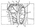
- FIG. 1 shows a perspective view of a fan according to the invention.
- the figure shows a perspective view of an inventive fan 1, which is installed in a fan room of a cooking appliance partially shown to rotate in the direction of arrow A rotating air in the cooking chamber, which is partially separated from the fan room by a not shown air deflector.
- the fan wheel 1 has a base plate 2 on which a plurality of fan blades 3 are arranged, which face the cooking chamber of the cooking appliance.
- the Lüfterradschaufeln 3 are curved and arranged substantially perpendicular to the base plate 2 to form a substantially radial arrangement on the base plate 2.
- Each fan blade 3 has a trailing edge 5 contacting the air to be circulated first during operation, and an outer surface 6 arranged on the pressure side of the fan wheel 1 during operation.
- an elevation 7 is provided, which extends away from the base plate 2, substantially diagonally from a front edge 4 to the trailing edge 5 of the Lüfterradschaufel 3.
- the elevation 7 is arranged at a distance of 10 to 20 mm from the base plate 2 on the outer surface 6.
- the elevation 7 may extend completely over the entire width of the Lüfterradschaufel 3, or have a distance from the base plate 2 opposite side of the Lüfterradschaufel 3, said distance is preferably 5 to 15 mm.
- a cover ring 8 is provided which provides additional stabilization of the fan blades 3 within the fan 1.
- the elevation 7 should stand out from the outer surface 6 of the Lüfterradschaufel 3 by 2 to 5 mm and end at the end facing the air flow on the trailing edge 5 of the Lüfterradschaufel 3 with a sharp edge to a gutter for impinging solid and / or liquid particles form, which prevents further flow of the solid and / or liquid particles beyond the elevation 7, but causes a guiding in the direction of the base plate 2.
- a seal may be provided on the side lying in the flow shadow between the outer surface 6 and elevation 7.
- This seal may be made, for example, with silicone, but any other seal may be provided which would be obvious to those skilled in the art.
- the fan 1 is rotated in the fan chamber via an engine, not shown in the figure in the direction of arrow A and thus sucks air from the cooking chamber via a central opening in the air baffle centrally and directs them radially outwards, so that they outside of the fan room passes through the baffle again in the cooking chamber.
- Solid and / or liquid particles in particular fat particles of different sizes, which reach in the area of the fan wheel 1, impact on the outer surfaces 6 of the fan blades 3, on the pressure side of the fan wheel, and are discharged along the elevation 7 in the direction of the base plate 2 , If the solids and / or liquid particles reach the end region of the elevation 7 at the front edge 4 of the fan blade 3 (and finally the base plate 2), then the solid and / or liquid particles then released can not directly contact a device radially surrounding the fan wheel 1, such as in the form of a heater, not shown, or a heat exchanger, not shown, are discharged.
- a device radially surrounding the fan wheel 1 such as in the form of a heater, not shown, or a heat exchanger, not shown
- the impeller according to the invention in a cooking appliance thus prevents solids and / or liquid particles from being deposited directly on a heating device surrounding the impeller 1, and also ensures that air circulated by the impeller 1 can be diverted substantially completely radially, since the Efficiency of the fan 1 is only slightly reduced by the increase 7.
- the fan 1 is replaced by the elevations 7 itself a higher stability.
Landscapes
- Engineering & Computer Science (AREA)
- Mechanical Engineering (AREA)
- General Engineering & Computer Science (AREA)
- Structures Of Non-Positive Displacement Pumps (AREA)
Description
Die vorliegende Erfindung betrifft ein Gargerät-Lüfterrad nach dem Oberbegriff von Anspruch 1.The present invention relates to a cooking appliance fan according to the preamble of
Lüfterräder sind aus dem Stand derTechnik allgemein bekannt und dienen in der Regel dazu, Luft umzuwälzen.
Lüfterräder sind in den unterschiedlichsten Formen bekannt, so sind beispielsweise Lüfterräder mit propellerartigen Flügeln oder auch mit schaufelartigen Flügeln bekannt. Ein Problem bei aus dem Stand der Technik bekannten Lüfterrädern ist, daß Feststoff- und/oder Flüssigkeitspartikel, die in der umgewälzten Luft vorhanden sind, sich auf den Flügeln des Lüfterrads abscheiden können, was zu einer Verschmutzung des Lüfterrads führt. Auch kann es durch die bekannten Lüfterräder zu einer unerwünschten Verteilung der Feststoff und/oder Flüssigkeitspartikel kommen.Fan wheels are well known in the art and typically serve to circulate air.
Fan wheels are known in a variety of forms, for example, fan wheels are known with propeller-like wings or with blade-like wings. One problem with fan wheels known in the art is that particulates and / or liquid particles present in the recirculated air may deposit on the blades of the fan wheel, resulting in fouling of the fan wheel. It can also come through the known fan wheels to an undesirable distribution of the solid and / or liquid particles.
Besonders problematisch ist die Umwälzung von Feststoff- und/oder Flüssigkeitspartikeln, insbesondere in Form von Fettpartikeln, wenn das Lüfterrad innerhalb eines Gargeräts angeordnet ist. Das Lüfterrad ist in einem Gargerät zumeist in einem von dem Garraum über ein Luftleitblech getrennten Lüfterraum angeordnet, saugt Luft aus dem Garraum an und leitet diese radial an die Umgebungswände ab, um so eine Luftströmung innerhalb des Gargeräts, vom Garraum in den Lüfterraum und wieder zurück zum Garraum, zu erzeugen. Konzentrisch um das Lüfterrad herum ist häufig eine Heizeinrichtung oder auch ein Wärmetauscher angeordnet, so daß umgewälzte Luft auch an dieser Heizeinrichtung oder diesem Wärmetauscher vorbei geleitet wird, um erwärmt zu werden. Dabei können während eines Garprozeßes auch innerhalb der umgewälzten Luft vorhandene Fettpartikel auf beispielsweise die Heizeinrichtung geleitet werden, wo sie verbrannt werden können, was zu einer Verminderung der Speisenqualität und zu einer Geruchsbelästigung führen kann. Dieses Problem stellt sich insbesondere dann, wenn die Luft innerhalb des Gargeräts permanent durch das Lüfterrad umgewälzt wird, wobei dann die Feststoff- und/oder Flüssigkeitspartikel durch die Umluftströmung ständig in dem Gasvolumen gehalten werden.Particularly problematic is the circulation of solid and / or liquid particles, in particular in the form of fat particles, when the fan is disposed within a cooking appliance. The fan wheel is arranged in a cooking appliance mostly in a separate from the cooking chamber via a baffle fan space, sucks air from the cooking chamber and directs them radially to the surrounding walls, so as an air flow within the cooking appliance, from the cooking chamber in the fan room and back to the cooking chamber, to produce. Concentric around the fan around a heater or a heat exchanger is often arranged so that circulating air is also passed to this heater or this heat exchanger to be heated. In this case, during a cooking process, fat particles present within the circulated air can be conducted to, for example, the heating device, where they can be burned, which can lead to a reduction in the quality of the food and to an odor nuisance. This problem arises in particular when the air within the cooking appliance is permanently circulated through the fan, in which case the solid and / or liquid particles are constantly held in the gas volume by the circulating air flow.
Um das Abscheiden von Feststoff- und/oder Flüssigkeitspartikelri, die durch das Lüfterrad umgewälzt werden, innerhalb eines Gargeräts zu verringern, ist aus der
Ferner ist aus der
Aus der
Nachteilig bei den aus dem Stand der Technik bekannten Vorrichtungen ist jedoch, daß der Wirkungsgrad des Lüfterrads durch die das Lüfterrad umgebenden oder in dem Lüfterrad angeordnete Zusatzvorrichtungen vermindert wird, da die Zusatzvorrichtungen praktisch ein Strömungshindernis für die umgewälzte Luft darstellen.A disadvantage of the known from the prior art devices, however, that the efficiency of the fan wheel is surrounded by the surrounding the fan or disposed in the fan additional devices, since the additional devices represent a flow obstacle for the circulating air practically.
Aufgabe der vorliegenden Erfindung ist es daher, das gattungsgemäße Lüfterrad dahingehend weiterzubilden, daß die Nachteile des Stands der Technik überwunden werden. Insbesondere soll verhindert werden, daß Feststoff- und/oder Flüssigkeitspartikel, die in einer in einem Gargerät umgewälzten Luft vorhanden sind, durch das Lüfterrad unmittelbar auf eine das Lüfterrad umgebende Heizeinrichtung oder einen Wärmetauscher gelangen, ohne daß der Wirkungsgrad des Lüfterrads signifikant verringert wird.Object of the present invention is therefore to develop the generic fan to the effect that the disadvantages of the prior art are overcome. In particular, it is intended to prevent solids and / or liquid particles present in a circulating air in a cooking appliance from passing directly through the fan wheel onto a heating device or heat exchanger surrounding the fan wheel, without the efficiency of the fan wheel being significantly reduced.
Die Aufgabe der vorliegenden Erfindung wird durch die Merkmale des Kennzeichens von Anspruch 1 gelöst. Weitere erfindungsgemäße Gargeräte-Lüfterräder sind in den Ansprüchen 2 bis 15 beschrieben.The object of the present invention is solved by the features of the characterizing part of
Der vorliegenden Erfindung liegt die überraschende Erkenntnis zugrunde, daß durch Erhöhungen auf den Außenflächen von Lüfterradschaufeln auf einer Grundplatte zum einen vermieden wird, daß in umgewälzter Luft enthaltene Feststoff- und/oder Flüssigkeitspartikel, insbesondere in Form von Fettpartikeln, unmittelbar radial durch das Lüfterrad umgelenkt werden. Vielmehrwerden Feststoff-und/oder Flüssigkeitspartikel, die auf die Außenflächen der Lüfterradschaufeln treffen, an der Erhöhung gestoppt und durch die besondere Geometrie der Erhöhung in Richtung der Grundplatte abgeleitet. Im Bereich der Grundplatte können die Feststoffund/oder Flüssigkeitspartikel dann von den Lüfterradschaufeln abgegeben werden, ohne Vorrichtungen zu treffen, die unmittelbar radial um das Lüfterrad angeordnet sind, wie beispielsweise eine Heizeinrichtung innerhalb eines Gargeräts.The present invention is based on the surprising finding that is avoided by elevations on the outer surfaces of fan blades on a base plate on the one hand that contained in circulating air solids and / or liquid particles, in particular in the form of fat particles are deflected directly radially by the fan , Rather, solid and / or liquid particles impinging on the outer surfaces of the fan blades are stopped at the elevation and diverted by the particular geometry of the elevation toward the baseplate. In the area of the base plate, the Solid and / or liquid particles are then discharged from the fan blades, without hitting devices that are arranged immediately radially around the fan, such as a heater within a cooking appliance.
Da die Feststoff- und/oder Flüssigkeitspartikel von den Lüfterradschaufein nicht unmittelbar auf das Lüfterrad radial umgebende Vorrichtungen, wie eine Heizeinrichtung, abgegeben werden, wird verhindert, daß insbesondere Fettpartikel auf der Heizeinrichtung verbrannt werden können, was zu einer Verminderung der Speisenqualität und zu einer Geruchsbelästigung führen könnte.Since the solid and / or liquid particles are discharged from the Lüfterradschaufein not directly on the fan radially surrounding devices such as a heater, it is prevented that in particular fat particles can be burned on the heater, resulting in a reduction in food quality and an odor could lead.
Zum anderen wird durch das erfindungsgemäße Lüfterrad auf überraschende Weise erreicht, daß der Wirkungsgrad des Lüfterrads nicht signifikant beeinträchtigt wird, da keine großen Hindernisse im radialen Strömungsverlauf der umgewälzten Luft angeordnet sind. Ferner können die auf den Außenseiten der Lütterradsschaufeln angeordneten Erhöhungen für eine zusätzliche Stabilität der Lüfterradschaufeln selbst sorgen.On the other hand is achieved by the fan according to the invention in a surprising manner that the efficiency of the fan is not significantly affected, since no major obstacles in the radial flow of the circulating air are arranged. Further, the elevations disposed on the outsides of the luster wheel blades can provide additional stability to the fan blades themselves.
Weitere Merkmale und Vorteile der Erfindung ergeben sich aus der nachfolgenden Beschreibung, in der ein Ausführungsbeispiel der Erfindung anhand einer aus einer einzigen Figur bestehende Zeichnung im Einzelnen erläutert ist. Dabei zeigt die Figur eine perspektivische Ansicht eines erfindungsgemäßen Lüfterrads.Further features and advantages of the invention will become apparent from the following description in which an embodiment of the invention with reference to a single figure figure is explained in detail. The figure shows a perspective view of a fan according to the invention.
Die Figur zeigt perspektivisch eine Ansicht auf ein erfindungsgemäßes Lüfterrad 1, das in einem Lüfterraum eines teilweise dargestellten Gargeräts einbaubar ist, um in Richtung des Pfeils A drehend Luft im Garraum, der vom Lüfterraum durch ein nicht dargestelltes Luftleitblech bereichsweise abgeteilt ist, zu zirkulieren. Das Lüfterrad 1 weisteine Grundplatte 2 auf, auf dereine Vielzahl von Lüfterradschaufeln 3 angeordnet sind, die zum Garraum des Gargeräts gewandt sind. Die Lüfterradschaufeln 3 sind gekrümmt ausgebildet und im wesentlichen senkrecht auf der Grundplatte 2 angeordnet, um eine im wesentlichen radiale Anordnung auf der Grundplatte 2 auszubilden. Jede Lüfterradschaufel 3 weist eine im Betrieb die zu zirkulierende Luft zuerst kontaktierende Hinterkante 5, und eine im Betrieb auf der Druckseite des Lüferrads 1 angeordnete Außenfläche 6 auf. Auf der Außenfläche 6 einer Lüfterradschaufel 3 ist zudem eine Erhöhung 7 vorgesehen, die sich von der Grundplatte 2 weg, im wesentlichen diagonal von einer Vorderkante 4 zur Hinterkante 5 der Lüfterradschaufel 3, erstreckt. Dabei ist die Erhöhung 7 mit einem Abstand von 10 bis 20 mm von der Grundplatte 2 auf der Außenfläche 6 angeordnet. Die Erhöhung 7 kann sich vollständig über die gesamte Breite der Lüfterradschaufel 3 erstrecken, oder einen Abstand zu der der Grundplatte 2 gegenüberliegenden Seite der Lüfterradschaufel 3 aufweisen, wobei dieser Abstand vorzugsweise 5 bis 15 mm beträgt. Auf derder Grundplatte 2 gegenüberliegenden Seite des Lüfterrads 1 ist ein Deckring 8 vorgesehen, der für eine zusätzliche Stabilisierung der Lüfterradschaufeln 3 innerhalb des Lüfterrads 1 sorgt. Die Erhöhung 7 sollte sich von der Außenfläche 6 der Lüfterradschaufel 3 um 2 bis 5 mm abheben und an dem der Luftströmung zugewandten Ende auf der Hinterkante 5 der Lüfterradschaufel 3 mit einer scharfen Kante enden, um eine Ablaufrinne für auftreffende Feststoff- und/oder Flüssigkeitspartikel zu bilden, die ein Weiterströmen der Feststoff- und/oder Flüssigkeitspartikel, über die Erhöhung 7 hinaus, verhindert, sondern ein Führen in Richtung der Grundplatte 2 bewirkt. Überdies kann eine Abdichtung auf der im Strömungsschatten liegenden Seite zwischen Außenfläche 6 und Erhöhung 7 vorgesehen sein.The figure shows a perspective view of an
Diese Abdichtung kann beispielsweise mit Silikon erfolgen, jedoch kann jede andere Abdichtung vorgesehen sein, die sich für einen Fachmann auf diesem Gebiet in naheliegender Weise ergibt.This seal may be made, for example, with silicone, but any other seal may be provided which would be obvious to those skilled in the art.
Die Funktionsweise des erfindungsgemäßen Lüfterrads 1 ist im Anschluß beschrieben.The operation of the
Das Lüfterrad 1 wird im Lüfterraum über einen nicht gezeigten Motor in der Figur in Richtung des Pfeils A gedreht und saugt somit Luft aus dem Garraum über eine mittige Öffnung im Luftleitblech zentral an und leitet diese radial nach außen ab, so daß sie aus dem Lüfterraum außen an Luftleitblechen vorbei wieder in dem Garraum gelangt. Feststoff- und/oder Flüssigkeitspartikel, insbesondere Fettpartikel unterschiedlicher Größe, welche in dem Bereich des Lüfterrads 1 gelangen, prallen dabei auf die Außenflächen 6 der Lüfterradsschaufeln 3, auf der Druckseite des Lüfterrads, und werden entlang der Erhöhung 7 in Richtung auf die Grundplatte 2 abgeleitet. Erreichen die Feststoff- und/oder Flüssigkeitspartikel den Endbereich der Erhöhung 7 an der Vorderkante 4 der Lüfterradschaufel 3 (und schließlich die Grundplatte 2), so können die dann abgegebenen Feststoff- und/oder Flüssigkeitspartikel nicht direkt an eine das Lüfterrad 1 radial umgebende Vorrichtung, wie beispielsweise in Form einer nicht dargestellten Heizvorrichtung oder eines nicht dargestellten Wärmetauschers, abgegeben werden. Durch dieses "Vorbeiführen" der Feststoff- und/oder Flüssigkeitspartikeln an einer Heizvorrichtung und/oder einem Wärmetauscher wird ein Verbrennen derselben vermieden, was zu einer Geruchsbelästigung und zu einer negativen Beeinflussung eines Garergebnisses führen kann. Statt dessen können die abgeschiedenen Feststoff-und/oder Flüssigkeitspartikel entsorgt werden.The
Das erfindungsgemäße Lüfterrad in einem Gargerät verhindert somit, daß Feststoff- und/oder Flüssigkeitspartikelbeispielsweise direkt auf einer das Lüfterrad 1 umgebende Heizeinrichtung abgeschieden warden können, und sorgt ferner dafür, daß von dem Lüfterrad 1 umgewälzte Luft im wesentlichen vollständig radial umgeleitet werden kann, da der Wirkungsgrad des Lüfterrads 1 durch die Erhöhung 7 nur unwesentlich verringert wird. Das Lüfterrad 1 erhält durch die Erhöhungen 7 selbst eine höhere Stabilität.The impeller according to the invention in a cooking appliance thus prevents solids and / or liquid particles from being deposited directly on a heating device surrounding the
Claims (15)
- A cooking-device fan impeller (1) in a fan chamber of a cooking device, said fan chamber being separated in regions from the cooking chamber of the cooking device by means of an air baffle in such a way that the fan impeller (1), when it is in operation, is rotated in the fan chamber by a motor and thus centrally sucks air from the cooking chamber via a centered aperture in the air baffle and conducts said air radially outward so that said air moves from the fan chamber along the outside of the air baffle back into the cooking chamber, wherein the fan impeller (1) is equipped with a baseplate (2) and a multiplicity of fan impeller blades (3) secured to the baseplate (2), the fan impeller blades (3) are arranged substantially perpendicular on the baseplate (2) and form a substantially radial arrangement, and each fan impeller blade (3) has a radially outer front edge (4) arranged substantially perpendicular to the baseplate (2), a radially inner rear edge (5) arranged substantially perpendicular to the baseplate (2), an outer face (6) arranged on the pressure side of the fan impeller (1) and an inner face arranged on the suction side of the fan impeller (1), characterized in that at least one elevation (7) is arranged and/or formed on the outer face (6) of at least some of the fan impeller blades (3), which elevation (7) is formed at a distance from the baseplate (2) and extends away from the baseplate (2), substantially diagonally from the front edge (4) to the rear edge (5) of the fan impeller blades (3), and a support member (8) of the fan impeller blades (3) is provided on the opposite side of the fan impeller blades (3) from the baseplate (2).
- The cooking-device fan impeller according to Claim 1, characterized in that the elevation (7) is produced in the form of a step on and/or in the outer face (6).
- The cooking-device fan impeller according to Claim 1 or 2, characterized in that the fan impeller blades (3) are curved in such a way that the outer face (6) curves radially outward between the front edge (4) and the rear edge (5).
- The cooking-device fan impeller according to any one of the preceding claims, characterized in that at least one elevation (7), at least in regions, has a height of approximately 1 to 10 mm, preferably 2 to 4 mm.
- The cooking-device fan impeller according to any one of the preceding claims, characterized in that at least one elevation (7), at least in regions, has a width from 1 to 10 mm, preferably 2 to 4 mm.
- The cooking-device fan impeller according to any one of the preceding claims, characterized in that the distance from at least one elevation (7) to the baseplate (2), at least in regions, in particular in the region of the front edge (4), is at least approximately 5 to 25 mm, preferably 10 to 20 mm.
- The cooking-device fan impeller according to any one of the preceding claims, characterized in that the support member (8) is in the form of a covering ring.
- The cooking-device fan impeller according to any one of the preceding claims, characterized in that at least one elevation (7), at least in regions, is arcuate in form, preferably bending away from the support member (8) from the respective rear edge (5) to the respective front edge (4).
- The cooking-device fan impeller according to any one of the preceding claims, characterized in that at least one elevation (7) meets the front edge (4) at an angle of from 45° to 90°, preferably at an angle of from 70° to 90°.
- The cooking-device fan impeller according to any one of the preceding claims, characterized in that at least one elevation (7), at least in regions, is at a distance from the support member (8), in particular in the region of the rear edge (5), of at least approximately 1 to 10 mm, preferably 5 to 15 mm.
- The cooking-device fan impeller according to any one of the preceding claims, characterized in that at least one elevation (7) is formed by at least one wire.
- The cooking-device fan impeller according to any one of the preceding claims, characterized in that at least one elevation (7), at least in regions, is welded to the outer face (6) of the fan impeller blade (3).
- The cooking-device fan impeller according to any one of the preceding claims, characterized in that on the outer face (6) of at least one fan impeller blade (3), preferably each fan impeller blade (3), in the securing region between the respective elevation (7) and the outer face (6), a pronounced edge, for example in the form of a channel, is formed at least in regions on the side which lies in the direction of rotation of the fan impeller.
- The cooking-device fan impeller according to any one of the preceding claims, characterized in that at least one elevation (7), at least in regions, has a profiled cross section, preferably is convex, with in particular the focal point of the convexity lying on that side of the elevation (7) which faces the rear edge (5), and/or having at least one groove, preferably on the side which faces the rear edge (5).
- The cooking-device fan impeller according to any one of the preceding claims, characterized in that at least one elevation (7), at least in regions, is joined in a sealed manner to the outer face (6), preferably using silicone, on the side which faces away from the direction of rotation of the fan impeller (1).
Applications Claiming Priority (3)
| Application Number | Priority Date | Filing Date | Title |
|---|---|---|---|
| DE10239246 | 2002-08-22 | ||
| DE10239246A DE10239246C1 (en) | 2002-08-22 | 2002-08-22 | Fan wheel for cooking appliance has projection extending diagonally across outer surface of each fan blade for preventing deposition of fat on heating or heat exchange device at rear of fan wheel |
| PCT/DE2003/002640 WO2004020837A1 (en) | 2002-08-22 | 2003-08-06 | Fan impeller with integrated precipitation of fat particles, in particular for a cooking device |
Publications (3)
| Publication Number | Publication Date |
|---|---|
| EP1530682A1 EP1530682A1 (en) | 2005-05-18 |
| EP1530682B1 EP1530682B1 (en) | 2006-05-31 |
| EP1530682B2 true EP1530682B2 (en) | 2015-04-15 |
Family
ID=27618865
Family Applications (1)
| Application Number | Title | Priority Date | Filing Date |
|---|---|---|---|
| EP20030790684 Expired - Lifetime EP1530682B2 (en) | 2002-08-22 | 2003-08-06 | Fan impeller with integrated precipitation of fat particles, in particular for a cooking device |
Country Status (5)
| Country | Link |
|---|---|
| US (1) | US7165942B2 (en) |
| EP (1) | EP1530682B2 (en) |
| JP (1) | JP4255912B2 (en) |
| DE (2) | DE10239246C1 (en) |
| WO (1) | WO2004020837A1 (en) |
Families Citing this family (16)
| Publication number | Priority date | Publication date | Assignee | Title |
|---|---|---|---|---|
| DE10239246C1 (en) | 2002-08-22 | 2003-08-21 | Rational Ag | Fan wheel for cooking appliance has projection extending diagonally across outer surface of each fan blade for preventing deposition of fat on heating or heat exchange device at rear of fan wheel |
| DE10315341C5 (en) * | 2003-04-03 | 2009-07-30 | Mkn Maschinenfabrik Kurt Neubauer Gmbh & Co. | Cooking device with a blower with radial impeller and separator |
| US7112043B2 (en) * | 2003-08-29 | 2006-09-26 | General Motors Corporation | Compressor impeller thickness profile with localized thick spot |
| EP1961969A3 (en) | 2007-02-26 | 2009-10-21 | Josip Pavetic | Radial fan wheel |
| EP1961966A1 (en) * | 2007-02-26 | 2008-08-27 | Josip Pavetic | Radial fan impeller |
| EP1961968A1 (en) | 2007-02-26 | 2008-08-27 | Josip Pavetic | Radial fan wheel and radial fan incorporating the same with locking protection |
| EP1961967A1 (en) * | 2007-02-26 | 2008-08-27 | Josip Pavetic | Radial fan wheel and radial fan incorporating the same |
| EP2143958A1 (en) | 2008-07-07 | 2010-01-13 | Josip Pavetic | Ventilator integrated into a tube |
| EP2284401B1 (en) | 2009-08-11 | 2013-01-30 | Rational AG | Ventilator wheel and cooking device |
| RU2522015C2 (en) * | 2009-10-27 | 2014-07-10 | Дженерал Электрик Компани | Drop catcher for centrifugal compressor |
| EP2372163B1 (en) | 2010-04-01 | 2014-10-08 | Convotherm Elektrogeräte GmbH | Fan |
| ITUB20152807A1 (en) * | 2015-08-03 | 2017-02-03 | Ma Ti Ka S R L | FAN FOR OVENS FOR COOKING FOOD |
| DE102016212162A1 (en) * | 2016-07-04 | 2018-01-04 | Convotherm-Elektrogeräte Gmbh | Commercial cooking appliance |
| DE102017203526B4 (en) | 2017-03-03 | 2026-03-05 | Welbilt Deutschland GmbH | fan wheel |
| DE102017203539A1 (en) | 2017-03-03 | 2018-09-06 | Convotherm-Elektrogeräte Gmbh | fan |
| WO2018158226A1 (en) | 2017-03-03 | 2018-09-07 | Convotherm-Elektrogeräte Gmbh | Fan wheel |
Citations (1)
| Publication number | Priority date | Publication date | Assignee | Title |
|---|---|---|---|---|
| DE3814721A1 (en) † | 1988-04-30 | 1989-11-09 | Asea Brown Boveri | RADIAL FAN WITH INTEGRATED DIRT SEPARATOR |
Family Cites Families (11)
| Publication number | Priority date | Publication date | Assignee | Title |
|---|---|---|---|---|
| US168345A (en) * | 1875-10-05 | Improvement in car-couplings | ||
| US262642A (en) * | 1882-08-15 | Fan-blower | ||
| US1688345A (en) | 1927-08-16 | 1928-10-23 | Buffalo Hammer Mill Corp | Centrifugal fan |
| DE729947C (en) | 1937-02-09 | 1943-01-05 | Danneberg & Quandt Alleiniger | Fan impeller |
| US2616764A (en) | 1948-05-22 | 1952-11-04 | Earl M Parrish | Wear resistant blower surface |
| FR2588925A1 (en) | 1985-10-23 | 1987-04-24 | Etri Sa | FAN EQUIPPED WITH MEANS TO REDUCE THE NOISE GENERATED BY THE ROTATION OF ITS BLADES |
| FR2606465B1 (en) | 1986-11-06 | 1989-01-13 | Ducellier & Cie | ROTATING ELECTRIC MACHINE FAN |
| DE4206846C2 (en) * | 1992-03-04 | 1995-11-16 | Rational Gmbh | Device for separating solid and / or liquid particles from a gas volume |
| DE4220960A1 (en) | 1992-06-25 | 1994-01-05 | Turbowerke Meisen Ventilatoren | Blades for axial and radial flow machines - use series of segments and connecting elements to create variable flow contour |
| DE4307405C1 (en) | 1993-03-09 | 1994-11-17 | Rational Gmbh | Fan wheel |
| DE10239246C1 (en) | 2002-08-22 | 2003-08-21 | Rational Ag | Fan wheel for cooking appliance has projection extending diagonally across outer surface of each fan blade for preventing deposition of fat on heating or heat exchange device at rear of fan wheel |
-
2002
- 2002-08-22 DE DE10239246A patent/DE10239246C1/en not_active Expired - Fee Related
-
2003
- 2003-08-06 DE DE50303600T patent/DE50303600D1/en not_active Expired - Lifetime
- 2003-08-06 WO PCT/DE2003/002640 patent/WO2004020837A1/en not_active Ceased
- 2003-08-06 JP JP2004531451A patent/JP4255912B2/en not_active Expired - Lifetime
- 2003-08-06 EP EP20030790684 patent/EP1530682B2/en not_active Expired - Lifetime
- 2003-08-06 US US10/525,192 patent/US7165942B2/en not_active Expired - Lifetime
Patent Citations (1)
| Publication number | Priority date | Publication date | Assignee | Title |
|---|---|---|---|---|
| DE3814721A1 (en) † | 1988-04-30 | 1989-11-09 | Asea Brown Boveri | RADIAL FAN WITH INTEGRATED DIRT SEPARATOR |
Also Published As
| Publication number | Publication date |
|---|---|
| JP4255912B2 (en) | 2009-04-22 |
| DE50303600D1 (en) | 2006-07-06 |
| DE10239246C1 (en) | 2003-08-21 |
| US20060165528A1 (en) | 2006-07-27 |
| EP1530682A1 (en) | 2005-05-18 |
| EP1530682B1 (en) | 2006-05-31 |
| US7165942B2 (en) | 2007-01-23 |
| WO2004020837A1 (en) | 2004-03-11 |
| JP2005536683A (en) | 2005-12-02 |
Similar Documents
| Publication | Publication Date | Title |
|---|---|---|
| EP1530682B2 (en) | Fan impeller with integrated precipitation of fat particles, in particular for a cooking device | |
| DE10158425C1 (en) | Cooking appliance with fan and water supply | |
| DE2849675C2 (en) | ||
| EP3255281A1 (en) | Ventilator with tandem diffuser blades | |
| DE29822687U1 (en) | Miniature heat sink | |
| DE102009054787A1 (en) | Separation device for separating particles for extractor hood, has acceleration unit with fan wheel and housing, where fan wheel is rotatable around rotational axis | |
| EP0833110B1 (en) | Oven with a blower | |
| DE202018105372U1 (en) | Device for extracting the spoil from exhaust air generated on a cooktop | |
| EP2350533A2 (en) | Flow directing device for a cooking appliance | |
| EP0615069B1 (en) | Fan rotor | |
| DE60120708T2 (en) | CENTRIFUGAL FAN | |
| DE10315341C5 (en) | Cooking device with a blower with radial impeller and separator | |
| EP3232127A1 (en) | Extractor hood with outlet grid | |
| EP1534959A1 (en) | Radial fan wheel for transporting cooling air for an electric machine | |
| EP3620721B1 (en) | Device for conduit extraction of exhaust air generated on a cooking hob | |
| CH684763A5 (en) | Extractor hood | |
| DE102005012557B4 (en) | Blower for an air handling unit | |
| DE19831087A1 (en) | Oven with blower assisted circulation promoting more uniform heating and browning even at lower air flow rates | |
| EP0457971B1 (en) | Cooking appliance using steam | |
| DE102017201906B4 (en) | Extractor device with filter element | |
| DE102005047457A1 (en) | Device, for cleaning cooking area climate, in form of fan in a steam or hot air steam or hot air or microwave device for cooking food on baking tray has fan with several blade units whereby each blade unit comprises of two blades | |
| EP1961966A1 (en) | Radial fan impeller | |
| DE102007026218A1 (en) | oven | |
| EP2284401B1 (en) | Ventilator wheel and cooking device | |
| DE4219642C1 (en) | Ventilation device contg. blower - involves blower outlet facing room to be served having number of air guide sheets moving delivered air from middle area of room to sides |
Legal Events
| Date | Code | Title | Description |
|---|---|---|---|
| PUAI | Public reference made under article 153(3) epc to a published international application that has entered the european phase |
Free format text: ORIGINAL CODE: 0009012 |
|
| 17P | Request for examination filed |
Effective date: 20050208 |
|
| AK | Designated contracting states |
Kind code of ref document: A1 Designated state(s): AT BE BG CH CY CZ DE DK EE ES FI FR GB GR HU IE IT LI LU MC NL PT RO SE SI SK TR |
|
| GRAP | Despatch of communication of intention to grant a patent |
Free format text: ORIGINAL CODE: EPIDOSNIGR1 |
|
| RBV | Designated contracting states (corrected) |
Designated state(s): DE FR GB IT |
|
| GRAS | Grant fee paid |
Free format text: ORIGINAL CODE: EPIDOSNIGR3 |
|
| GRAA | (expected) grant |
Free format text: ORIGINAL CODE: 0009210 |
|
| AK | Designated contracting states |
Kind code of ref document: B1 Designated state(s): DE FR GB IT |
|
| REG | Reference to a national code |
Ref country code: GB Ref legal event code: FG4D Free format text: NOT ENGLISH |
|
| REF | Corresponds to: |
Ref document number: 50303600 Country of ref document: DE Date of ref document: 20060706 Kind code of ref document: P |
|
| GBT | Gb: translation of ep patent filed (gb section 77(6)(a)/1977) |
Effective date: 20060908 |
|
| ET | Fr: translation filed | ||
| PLBI | Opposition filed |
Free format text: ORIGINAL CODE: 0009260 |
|
| 26 | Opposition filed |
Opponent name: EKOVENT D.O.O. Effective date: 20070228 |
|
| PLAX | Notice of opposition and request to file observation + time limit sent |
Free format text: ORIGINAL CODE: EPIDOSNOBS2 |
|
| PLAF | Information modified related to communication of a notice of opposition and request to file observations + time limit |
Free format text: ORIGINAL CODE: EPIDOSCOBS2 |
|
| PLBB | Reply of patent proprietor to notice(s) of opposition received |
Free format text: ORIGINAL CODE: EPIDOSNOBS3 |
|
| PLAB | Opposition data, opponent's data or that of the opponent's representative modified |
Free format text: ORIGINAL CODE: 0009299OPPO |
|
| PLAB | Opposition data, opponent's data or that of the opponent's representative modified |
Free format text: ORIGINAL CODE: 0009299OPPO |
|
| R26 | Opposition filed (corrected) |
Opponent name: EKOVENT D.O.O. Effective date: 20070228 |
|
| PLAY | Examination report in opposition despatched + time limit |
Free format text: ORIGINAL CODE: EPIDOSNORE2 |
|
| PLBC | Reply to examination report in opposition received |
Free format text: ORIGINAL CODE: EPIDOSNORE3 |
|
| PGFP | Annual fee paid to national office [announced via postgrant information from national office to epo] |
Ref country code: GB Payment date: 20130823 Year of fee payment: 11 |
|
| PUAH | Patent maintained in amended form |
Free format text: ORIGINAL CODE: 0009272 |
|
| STAA | Information on the status of an ep patent application or granted ep patent |
Free format text: STATUS: PATENT MAINTAINED AS AMENDED |
|
| 27A | Patent maintained in amended form |
Effective date: 20150415 |
|
| AK | Designated contracting states |
Kind code of ref document: B2 Designated state(s): DE FR GB IT |
|
| REG | Reference to a national code |
Ref country code: DE Ref legal event code: R102 Ref document number: 50303600 Country of ref document: DE |
|
| GBPC | Gb: european patent ceased through non-payment of renewal fee |
Effective date: 20140806 |
|
| REG | Reference to a national code |
Ref country code: DE Ref legal event code: R102 Ref document number: 50303600 Country of ref document: DE Effective date: 20150415 |
|
| PG25 | Lapsed in a contracting state [announced via postgrant information from national office to epo] |
Ref country code: GB Free format text: LAPSE BECAUSE OF NON-PAYMENT OF DUE FEES Effective date: 20140806 |
|
| REG | Reference to a national code |
Ref country code: FR Ref legal event code: PLFP Year of fee payment: 14 |
|
| REG | Reference to a national code |
Ref country code: FR Ref legal event code: PLFP Year of fee payment: 15 |
|
| REG | Reference to a national code |
Ref country code: FR Ref legal event code: PLFP Year of fee payment: 16 |
|
| PGFP | Annual fee paid to national office [announced via postgrant information from national office to epo] |
Ref country code: IT Payment date: 20220831 Year of fee payment: 20 Ref country code: DE Payment date: 20220822 Year of fee payment: 20 |
|
| PGFP | Annual fee paid to national office [announced via postgrant information from national office to epo] |
Ref country code: FR Payment date: 20220822 Year of fee payment: 20 |
|
| REG | Reference to a national code |
Ref country code: DE Ref legal event code: R071 Ref document number: 50303600 Country of ref document: DE |