EP1530305A2 - Système, procédé et dispositif de communication sans fil - Google Patents
Système, procédé et dispositif de communication sans fil Download PDFInfo
- Publication number
- EP1530305A2 EP1530305A2 EP04292628A EP04292628A EP1530305A2 EP 1530305 A2 EP1530305 A2 EP 1530305A2 EP 04292628 A EP04292628 A EP 04292628A EP 04292628 A EP04292628 A EP 04292628A EP 1530305 A2 EP1530305 A2 EP 1530305A2
- Authority
- EP
- European Patent Office
- Prior art keywords
- transmitter
- receiver
- antennas
- signal
- antenna
- Prior art date
- Legal status (The legal status is an assumption and is not a legal conclusion. Google has not performed a legal analysis and makes no representation as to the accuracy of the status listed.)
- Granted
Links
- 238000000034 method Methods 0.000 title claims abstract description 40
- 238000004891 communication Methods 0.000 title claims description 90
- 239000011159 matrix material Substances 0.000 claims abstract description 144
- 238000000354 decomposition reaction Methods 0.000 claims abstract description 37
- 239000013598 vector Substances 0.000 claims abstract description 37
- 238000012546 transfer Methods 0.000 claims description 85
- 230000005540 biological transmission Effects 0.000 abstract description 37
- 238000012549 training Methods 0.000 description 18
- 238000010276 construction Methods 0.000 description 7
- 238000012545 processing Methods 0.000 description 7
- 230000000694 effects Effects 0.000 description 5
- 230000001747 exhibiting effect Effects 0.000 description 5
- 238000005516 engineering process Methods 0.000 description 4
- 230000008901 benefit Effects 0.000 description 3
- 230000002708 enhancing effect Effects 0.000 description 3
- 230000003044 adaptive effect Effects 0.000 description 2
- 238000004364 calculation method Methods 0.000 description 2
- 239000000969 carrier Substances 0.000 description 2
- 238000004590 computer program Methods 0.000 description 2
- 230000007246 mechanism Effects 0.000 description 2
- 230000006855 networking Effects 0.000 description 2
- 239000000654 additive Substances 0.000 description 1
- 230000000996 additive effect Effects 0.000 description 1
- 238000001514 detection method Methods 0.000 description 1
- 238000010586 diagram Methods 0.000 description 1
- 230000006872 improvement Effects 0.000 description 1
- 230000000977 initiatory effect Effects 0.000 description 1
- 238000004519 manufacturing process Methods 0.000 description 1
- 238000012986 modification Methods 0.000 description 1
- 230000004048 modification Effects 0.000 description 1
- 230000010363 phase shift Effects 0.000 description 1
- 230000008054 signal transmission Effects 0.000 description 1
- 238000006467 substitution reaction Methods 0.000 description 1
Images


Classifications
-
- H—ELECTRICITY
- H04—ELECTRIC COMMUNICATION TECHNIQUE
- H04L—TRANSMISSION OF DIGITAL INFORMATION, e.g. TELEGRAPHIC COMMUNICATION
- H04L1/00—Arrangements for detecting or preventing errors in the information received
- H04L1/02—Arrangements for detecting or preventing errors in the information received by diversity reception
- H04L1/06—Arrangements for detecting or preventing errors in the information received by diversity reception using space diversity
- H04L1/0618—Space-time coding
- H04L1/0637—Properties of the code
- H04L1/0656—Cyclotomic systems, e.g. Bell Labs Layered Space-Time [BLAST]
-
- H—ELECTRICITY
- H04—ELECTRIC COMMUNICATION TECHNIQUE
- H04B—TRANSMISSION
- H04B7/00—Radio transmission systems, i.e. using radiation field
- H04B7/02—Diversity systems; Multi-antenna system, i.e. transmission or reception using multiple antennas
- H04B7/04—Diversity systems; Multi-antenna system, i.e. transmission or reception using multiple antennas using two or more spaced independent antennas
- H04B7/0413—MIMO systems
- H04B7/0417—Feedback systems
- H04B7/0421—Feedback systems utilizing implicit feedback, e.g. steered pilot signals
-
- H—ELECTRICITY
- H04—ELECTRIC COMMUNICATION TECHNIQUE
- H04B—TRANSMISSION
- H04B7/00—Radio transmission systems, i.e. using radiation field
- H04B7/02—Diversity systems; Multi-antenna system, i.e. transmission or reception using multiple antennas
- H04B7/04—Diversity systems; Multi-antenna system, i.e. transmission or reception using multiple antennas using two or more spaced independent antennas
- H04B7/06—Diversity systems; Multi-antenna system, i.e. transmission or reception using multiple antennas using two or more spaced independent antennas at the transmitting station
- H04B7/0613—Diversity systems; Multi-antenna system, i.e. transmission or reception using multiple antennas using two or more spaced independent antennas at the transmitting station using simultaneous transmission
- H04B7/0615—Diversity systems; Multi-antenna system, i.e. transmission or reception using multiple antennas using two or more spaced independent antennas at the transmitting station using simultaneous transmission of weighted versions of same signal
- H04B7/0619—Diversity systems; Multi-antenna system, i.e. transmission or reception using multiple antennas using two or more spaced independent antennas at the transmitting station using simultaneous transmission of weighted versions of same signal using feedback from receiving side
-
- H—ELECTRICITY
- H04—ELECTRIC COMMUNICATION TECHNIQUE
- H04B—TRANSMISSION
- H04B7/00—Radio transmission systems, i.e. using radiation field
- H04B7/02—Diversity systems; Multi-antenna system, i.e. transmission or reception using multiple antennas
- H04B7/04—Diversity systems; Multi-antenna system, i.e. transmission or reception using multiple antennas using two or more spaced independent antennas
- H04B7/08—Diversity systems; Multi-antenna system, i.e. transmission or reception using multiple antennas using two or more spaced independent antennas at the receiving station
- H04B7/0837—Diversity systems; Multi-antenna system, i.e. transmission or reception using multiple antennas using two or more spaced independent antennas at the receiving station using pre-detection combining
- H04B7/0842—Weighted combining
-
- H—ELECTRICITY
- H04—ELECTRIC COMMUNICATION TECHNIQUE
- H04L—TRANSMISSION OF DIGITAL INFORMATION, e.g. TELEGRAPHIC COMMUNICATION
- H04L1/00—Arrangements for detecting or preventing errors in the information received
- H04L1/02—Arrangements for detecting or preventing errors in the information received by diversity reception
- H04L1/06—Arrangements for detecting or preventing errors in the information received by diversity reception using space diversity
- H04L1/0618—Space-time coding
Definitions
- the present invention relates to a system, apparatus, method and computer program for a wireless communication among a plurality of wireless stations, such as a communication by a wireless LAN (Local Area Network).
- the invention relates to such a system, method and apparatus which realize a broadband wireless transmission in home or other similar communication environments.
- this invention relates to a system, apparatus, method and computer program which enhance the transmission capacity by employing a communication where a transmitter and a receiver each having a plurality of antennas communicate with each other using space division multiplexing, that is, MIMO communication; in particular, the invention relates to such a system, method and apparatus, which are adapted to perform MIMO transmission using a singular value decomposition (SVD) of a channel information matrix each element in which represents propagation information of one of sub-channels each linking a pair of an antenna of the transmitter and an antenna of the receiver.
- SSD singular value decomposition
- Wireless LAN is attracting attention of people as a system for relieving users from the conventional wired LAN construction.
- a working space such as an office
- most of cables and wires can be dispensed with by employing a wireless LAN, facilitating relocation of a communication terminal such as a personal computer.
- PAN Personal Area Network
- IEEE 802.11 the Institute of Electrical and Electronics Engineers 802.11 (see nonpatent literature 1). IEEE 802.11 standard is further divided, depending upon the employed methods and used frequencies, into IEEE 802.11a, IEEE 802.11b...etc., defining respective wireless communications methods.
- IEEE 802.11a standard supports a modulation method achieving a communication speed of up to 54Mbps.
- MIMO Multi-Input Multi-Output
- This technology is for enhancing the communication speed by providing both of the transmitter and receiver with a plurality of antennas, so as to realize space division multiplexing, i.e., a plurality of sub-channels which are logically independent of one another, to increase the transmission capacity.
- space division multiplexing i.e., a plurality of sub-channels which are logically independent of one another, to increase the transmission capacity.
- MIMO is bandwidth-efficient.
- Fig. 7 schematically shows a MIMO communications system, where each of a transmitter and a receiver is equipped with a plurality of antennas.
- the transmitter space-time encodes N data for transmission to be multiplexed, and distributes the encoded data to M antennas of the transmitter from which the data are sent over a channel to the receiver in a multiplexed fashion.
- the receiver receives and space-time decodes the data received through N antennas thereof via the channel, to obtain received data.
- a MIMO communication is not the same as a communication by a simple transmission/reception adaptive array.
- the channel model involves an RF environment (transfer function) on the side of the transmitter, a construction (transfer function) of the channel space, and an RF environment (transfer function) on the side of the receiver.
- a MIMO system is such that the transmitter sends out the transmitted data or signal by distributing components of the data to the plural antennas thereof (hereinafter referred to as “transmit antennas"), and the receiver obtains received data by processing the signal components received through the plural antennas thereof (hereinafter referred to as “receive antennas”), and is a communications system utilizing a characteristic of the channel.
- transmit antennas the plural antennas thereof
- receiver antennas the receiver obtains received data by processing the signal components received through the plural antennas thereof
- SVD-MIMO system as one of ideal modes of MIMO is known that uses SVD (Singular Value Decomposition) of a propagation function. See Patent Document 2, and Nonpatent Literature 2, for instance.
- Fig. 8 schematically shows a SVD-MIMO transmission system, where a matrix of numbers, i.e., a channel information matrix H, each of whose elements represents information on each of sub-channels linking respective antenna pairs, is subjected to a singular value decomposition to obtain UDV H , and an antenna weighting coefficient matrix V on the part of the transmitter (hereinafter referred to as “transmit antenna weighting coefficient matrix V”) and an antenna weighting coefficient matrix U H" on the part of the receiver (hereinafter referred to as “receive antenna weighting coefficient matrix U H”) are provided.
- the channel information is expressed by a diagonal matrix whose diagonal elements are square roots of respective eigenvalues ⁇ i .
- a signal can be transmitted in a multiplexed fashion without suffering from crosstalk at all.
- the set-up procedure such that the derived V or U H is beforehand communicated to the other part of the communication is essential.
- transmitted signal x is represented as vector (M ⁇ 1) while the received signal y is represented by vector (N ⁇ 1).
- the channel information can be represented as a matrix H of N ⁇ M.
- An entry h ij of the channel information matrix H represents a transfer function with respect to a sub-channel from a j-th transmit antenna to an i-th receive antenna.
- the transmit antenna weighting coefficient matrix V and receive antenna weighting coefficient matrix U are unitary matrices which respectively satisfy the following equations (3) and (4):
- the receive antenna weighting coefficient matrix U H is an array of normalized eigenvectors of HH H
- the transmit antenna weighting coefficient matrix V is an array of normalized eigenvectors of H H H
- D represents a diagonal matrix whose diagonal elements are square roots of respective eigenvalues of H H H or HH H .
- the size of the matrix D corresponds to the smaller one of the numbers M and N of the transmit antennas and receive antennas, that is, the matrix D is a square diagonal matrix having a rank of min(M, N).
- V is obtained as a matrix of eigenvectors of H H H as ordinary, while U is obtained by multiplying both terms of the equation (2) by V, as expressed by the following equation (6):
- HV UDV
- the transmitter weights the components of the signal for respective sub-channels by the transmit antenna weighting coefficient matrix V, while the receiver receives the signal with weighting the components by an inverse weighting coefficient matrix U H ; since each of U and V is a unitary matrix (U is a matrix of N ⁇ min(M, N) while V is a matrix of M ⁇ min(M, N)), the following expression is obtained:
- the vectors y and x are not determined by the numbers of the antennas of the transmitter and the receiver, but are respectively expressed by (min(M, N) ⁇ 1).
- each transmitted signal can be received without suffering from the crosstalk.
- the amplitude of each of the sub-channels which are independent from one another is proportional to the square root of the eigenvalue ⁇ , and thus the power of each sub-channel is proportional to ⁇ .
- U H n is a vector whose size is min(M, N), which is the same size as y and x.
- the receiver In the SVD-MIMO system, the receiver must obtain the channel information matrix H, implement the singular value decomposition, and communicate V H as a factor of UDV H obtained as the result of the decomposition to the transmitter. In effect, the transmitter uses V and therefore V must be communicated to the transmitter.
- the transmit antenna weighting coefficient matrix V is a 3 ⁇ 3 matrix, having nine elements.
- each element is a complex number represented using 10 bits, and 52 carriers are provided, a total of 9360 bits of information, i.e., 9 (the number of elements of the matrix) ⁇ 2 (the real and imaginary part of a complex number) ⁇ 10 ⁇ 52 (the number of OFDM sub-carriers), has to be fed back to the transmitter from the receiver.
- closed-loop MIMO The MIMO requiring such feedback is called closed-loop MIMO, while the opposite thereof is open-loop MIMO.
- a closed-loop SVD-MIMO system must feedback information of that much (9360 bits) to the transmitter, upon initiation of a communication.
- the information is fed back where the most reliable one in the modulation schemes provided by IEEE 802.11a, i.e., BPSK is employed as a first modulation method, the coding rate is 1/2, and OFDM is employed as a second modulation method. Since 1 OFDM symbol can carry only 24 bits, 390 OFDM symbols are required for the transmission of the information, making the SVD-MIMO unpractical.
- V-BLAST is an acronym of "Vertical Bell Laboratories Layered Space Time" and refers to a technology originally developed by the now-defunct AT & T Bell Laboratories. See Patent Documents 1, for instance.
- Fig. 9 schematically shows a structure of a V-BLAST communications system.
- the major difference between the V-BLAST and SVD-MIMO systems is that the transmitter in the V-BLAST does not provide the antenna weighting coefficient matrix V, but simply multiplexes a signal with respect to the transmit antennas and the feedback processing for beforehand providing the antenna weighting coefficient matrix V is all omitted.
- the transmitter inserts, prior to sending the multiplexed signal, training signals to be used in channel estimation by the receiver, in the multiplexed signal. For instance, the training signals for respective antennas are inserted in the signal in a time division fashion.
- the training signals are sent included in the data packet such that a training signal Training-1 corresponding to an antenna #1 is sent following a preamble signal and a training signal Training-2 corresponding to an antenna #2 is subsequently sent, in a time division fashion.
- a channel estimator thereof performs a channel estimation using the training signals, to calculate the channel information matrix H representing information on the sub-channels linking respective antenna pairs.
- a first antenna weighting coefficient matrix calculator performs zero-forcing or others for each of signals corresponding to the respective transmit antennas so as to cancel unnecessary signals, i.e., signals other than those for the respective receive antennas, and obtains a receive antenna weighting coefficient matrix Z R .
- the transmitted signal having the highest S/N ratio among the signals retrieved after Z R is provided, is first decoded to obtain a signal x 1 .
- the decoded signal is encoded again by an encoder to generate a replica (duplicate) of the transmitted signal x 1 , which is canceled from the signals just received by the receive antennas.
- a second receive antenna weighting coefficient matrix calculator excludes the transmit antenna corresponding to the transmitted signal x 1 as canceled, and again applies zero-forcing criteria to each of the other signals, to calculate a receive antenna weighting coefficient matrix Z R '.
- the signal x 2 exhibiting the highest S/N ratio among the remaining received signals is decoded by the decoder.
- V-BLAST a characteristic of the V-BLAST resides in that zero-forcing and canceling are sophisticatedly combined so that even a signal whose S/N ratio can not be made sufficiently high only by application of zero-forcing criteria can be improved in S/N ratio by taking advantage of the degree of freedom of the antennas which is provided by the canceling, and thus the accuracy of the decoding is enhanced.
- the V-BLAST can realize an efficient MIMO transmission system by a combination of relatively simple mechanisms.
- the receiver since the transmitter does not perform the weighting before the data transmission, the receiver is required to implement the first decoding only by zero-forcing, without performing the canceling operation.
- the number of receive antennas is made larger than that of the transmit antennas so as to obtain a redundancy in degree of freedom of the receive antennas.
- two transmit antennas and three receive antennas are provided.
- a first object of the present invention is to provide an excellent wireless communications system, wireless communication method and wireless communications apparatus, which realizes a broadband wireless transmission under a communication environment such as in a home.
- a second object of the invention is to provide an excellent wireless communications system, wireless communication method and wireless communications apparatus, which can enhance the transmission capacity by implementing a communication (MIMO communication) using space division multiplexing between a transmitter and a receiver each having a plurality of antennas.
- MIMO communication multiplexing
- a third object of the invention is to provide an excellent wireless communications system, wireless communication method and wireless communications apparatus, which can suitably implement a MIMO communication using a singular value decomposition (SVD) of a channel information matrix whose elements respectively represent a gain on each sub-channel linking a pair of a transmitter and a receiver.
- SMD singular value decomposition
- a fourth object of the invention is to provide an excellent wireless communications system, wireless communication method and wireless communications apparatus, which can reduce an amount of information fed back from a receiver to a transmitter in a SVD-MIMO transmission.
- the present invention has been developed for attaining the above-described objects, and a first aspect of the invention provides a wireless communications system for a communication between a transmitter and a receiver each having a plurality of antennas, over a communications channel by multiplexing a signal, the system comprising:
- system means a logical assembly of a plurality of apparatuses (or functional modules for realizing respective specific functions); the apparatuses or functional modules may or may not be enclosed in a single housing.
- the receiver instead of feeding back the antenna weighting coefficient matrix V of the transmitter, which is obtained by performing a singular value decomposition of the channel information matrix obtained by the receiver, the receiver sends the reference signals or symbols to the transmitter on which part a singular value decomposition is performed to obtain a transmit antenna weighting coefficient matrix V necessary when transmitting data.
- the receiver instead of feeding back the antenna weighting coefficient matrix V of the transmitter, which is obtained by performing a singular value decomposition of the channel information matrix obtained by the receiver, the receiver sends the reference signals or symbols to the transmitter on which part a singular value decomposition is performed to obtain a transmit antenna weighting coefficient matrix V necessary when transmitting data.
- the transmitter sends data where the transmit antenna weighting coefficient matrix V is applied, the receiver can obtain a satisfactory decoding capability with a reduced number of antennas.
- a second aspect of the invention provides a wireless communications system taking account of a transfer function of a communications channel between a transmitter and a receiver each having an antenna, the system comprising:
- the wireless communications system employs a scheme where each of the transmitter and receiver has plural antennas, and a signal is multiplexed to be sent over a plurality of sub-channels each linking an antenna of the transmitter and an antenna of the receiver.
- the calibration coefficient obtainer obtains calibration coefficients of the respective antennas on the part of both the transmitter and the receiver, while the reference signal feedback unit sends, by time division, the reference signals for the respective antennas of the receiver (hereinafter referred to as "receive antennas") as compensated by using the respective calibration coefficients.
- the transfer function calculator operates on the part of the transmitter to: compensate the reference signals received by the antennas of the transmitter (hereinafter referred to as the "transmit antennas"), by using the calibration coefficients for the respective antennas; calculate the transfer functions based on the compensated reference signals; obtain a channel information matrix H' in the inverse direction from the receiver to the transmitter, whose elements represent the transfer functions of the respective sub-channels; and acquire a transmit antenna weighting coefficient matrix V whose entries represent weighting vectors of the respective transmit antennas, by performing a singular value decomposition of the channel information matrix H' to yield U'D'V' H .
- the data sender sends the components of the signal from the respective antennas of the transmitter to the receiver with the components weighted by the respective weighting vectors.
- the transmitter sends the reference signals for the respective transmit antennas by time division, and the receiver calculates the transfer functions based on the reference signals received by the respective receive antennas so as to obtain a channel information matrix H in the forward direction whose elements represent the transfer functions of the sub-channels each linking a transmit antenna and a receive antenna, performs a singular value decomposition of the channel information matrix H to yield UDV H to obtain the receive antenna weighting coefficient matrix U whose element vectors represent the weighting vectors of the respective receive antennas.
- the receiver receives the data transmitted in the form of the data signals through the receive antennas, and decodes the signals using the receive antenna weighting coefficient matrix U H .
- the receiver instead of performing a singular value decomposition of the channel information matrix H as received by the receiver to yield UDV H so as to obtain the transmit antenna weighting coefficient matrix V and feeding back the matrix V to the transmitter, the receiver sends the reference signals or symbols to the transmitter, thereby reducing an amount of information fed back to the transmitter from the receiver.
- the antenna weighting coefficient matrix V' which is obtained by sending the reference signals or symbols from the receiver to the transmitter and performing the singular value decomposition on the part of the transmitter does not coincide with the antenna weighting coefficient matrix V in the direction from the transmitter to the receiver.
- the calibration coefficients of the antennas of the transmitter and receiver are obtained, and the calibration coefficients for the receive antennas is used for calibrating the reference signals upon feedback thereof while the calibration coefficients for the transmit antennas is used when calculating the transfer functions based on the reference signals.
- the noncoincidence between the channel information matrices in the opposite directions can be compensated for.
- the invention can provide the excellent wireless communications system, wireless communication method and wireless communications apparatus, where the pair of the transmitter and receiver each having the plural antennas is capable of making a communication using space division multiplexing (MIMO communication) in which the transmission capacity is enhanced.
- MIMO communication space division multiplexing
- the invention can provide the excellent wireless communications system, wireless communication method and wireless communications apparatus, which are capable of performing a MIMO transmission using the singular value decomposition (SVD) of the channel information matrix each of whose elements corresponds to the characteristic of each sub-channel linking each pair of a transmit antenna and a receive antenna.
- SMD singular value decomposition
- the invention can also provide the excellent wireless communications system, wireless communications method and wireless communications apparatus, which are capable of reducing the amount of information fed back from the receiver to the transmitter in performing the SVD-MIMO transmission.
- the receiver instead of performing a singular value decomposition of the channel information matrix as received by the receiver to obtain the transmit antenna weighting coefficient matrix V and feeding back the obtained matrix V to the transmitter, the receiver sends the reference signals or symbols to the transmitter which performs a singular value decomposition to obtain the transmit antenna weighting coefficient matrix V necessary when transmitting data.
- an amount of information fed back to the transmitter from the receiver can be reduced.
- the noncoincidence between the channel information matrices in the opposite directions can be compensated for, by implementing a calibration for compensating an error related to a transmission/reception analog device of both of the transmitter and the receiver.
- a receiver does not feed back to a transmitter a transmit antenna weighting coefficient matrix V as obtained by performing a singular value decomposition of a channel information matrix H obtained by the receiver to yield UDV H , but sends reference signals or symbols to a transmitter, so that the transmitter performs a singular value decomposition to obtain the transmit antenna weighting coefficient matrix V necessary when transmitting data.
- the amount of information fed back to the transmitter from the receiver can be thus reduced.
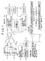
- Fig. 1 schematically shows a construction of an SVD-MIMO communications system according to a first embodiment of the invention.
- a transmitter space-time encodes each transmitted signal to multiplex the signal and distributes the multiplexed signal to three antennas to send the signal therefrom to a receiver over a channel.
- the receiver receives the multiplexed signal via the channel through two antennas and space-time decodes the signal to obtain received signal or data.
- the communications system shown resembles the V-BLAST system shown in Fig. 9 in general.
- the transmitter not the receiver, provides an antenna weighting coefficient when transmitting the data, and the antenna configuration of the transmitter and receiver is such that the number of the transmit antennas is larger than that of the receive antennas.
- the number of the receive antennas corresponds to the number of signal sub-channels.
- the part of the transmitter has a redundancy in the degree of freedom of the antennas.
- the transmitter sends a signal weighted by MSN (Maximum Signal-to-Noise ratio) which is criteria for maximizing the S/N ratio of signal of self, by zero-forcing, or by a combination of the MSN and zero-forcing.
- MSN Maximum Signal-to-Noise ratio
- a training signal "Pre-training Signal” as a reference symbol with respect to each antenna is sent from the receiver 20 in a time division fashion.
- the receiver has two receive antennas, and therefore two Pre-training Signals are sent.
- a preamble "Preamble" prefixed to the "Pre-training Signal” is an additive signal for serving a signal detection, a timing synchronization and an adjustment of receiver gain.
- the transmitter 10 receives the training signal from the receiver 20 as a reference signal, calculates the channel information matrix H by a channel estimator 11 of the transmitter 10, and determines a transmit antenna weighting coefficient matrix Z T by a transmit antenna weighting coefficient matrix calculator 13 by applying the MSN, zero-forcing, or combination of these, with respect to each antenna.
- the transmitter 10 sends a concatenation of training signals and a signal as a component of the signal indicative of the data of interest, which is obtained by multiplexing the signal by space division.
- the training signals are weighted for reflecting the characteristics of the respective corresponding antennas by using the matrix Z T obtained as described above. It is particularly noted that even in the period where the training signals are sent out, the weighting for reflecting the characteristics of the corresponding antennas is performed for each signal multiplexed.
- a channel estimator 21 of the receiver 20 calculates a channel information matrix H' each element of which corresponds to a pair of one of the transmit weighting coefficient vectors and a corresponding receive antenna, based on the training signals Training-1 and -2 as weighted with respect to respective signal components sent in a multiplexed fashion.
- a first receive antenna weighting coefficient matrix calculator 22 performs zero-forcing for each transmit antenna to cancel the unnecessary signals other than a signal related to the receive antenna itself, so as to obtain a receive antenna weighting coefficient matrix Z R .
- the signal exhibiting the highest S/N ratio is first decoded by a decoder 23 into x 1 .
- the encoder 24 encodes the signal as decoded once again to produce a replica (duplicate) of the transmitted signal, which is canceled from a signal just received by the antenna.
- a second receive antenna weighting coefficient matrix calculator 25 excludes the corresponding transmit antenna and performs again zero-forcing for the signal to calculate a receive antenna weighting coefficient matrix Z R '.
- the signal x 2 exhibiting the highest S/N ratio among the remaining received signals is retrieved to be decoded by the decoder 23.
- the degree of freedom of the receive antennas is increased, accordingly enhancing the effect of maximal ratio combining.
- the first embodiment is such that the transmitter 10 performs transmission of signals by using the MSN, zero-forcing, or combination of these, in weighting the signals.
- the degree of freedom of the transmit antennas is fully exploited, enhancing the S/N ratio of the received signals.
- the redundancy of the degree of freedom on the part of the transmitter can compensate this.
- Fig. 2 is a diagram illustrating a construction of a communications system according to a second embodiment of the invention.
- the system of Fig. 2 is identical with the system of Fig. 1 in that each transmitted signal multiplexed on the part of the transmitter is space-time decoded to be distributed to plural antennas through which the signal components are sent to the receiver over respective sub-channels of a channel in a multiplexed fashion, and the receiver space-time decodes the signal components received through plural antennas via the sub-channels to obtain a received signal or data.
- the transmit antenna weighting coefficient matrix calculator 13 determines, for each antenna, the transmit antenna weighting coefficient matrix Z T by the MSN, zero-forcing, or combination of these, based on the channel information matrix H obtained by a calculation using the training signals from the receiver 20.
- the second embodiment shown in Fig. 2 is such that a singular value decomposition unit 15 employs the SVD (Singular Value Decomposition) in calculating the transmit antenna weighting coefficient, and weights the signal by the weighting coefficient matrix V before transmission of the signal.
- SVD Single Value Decomposition
- the weighting coefficient matrix on the part of the receiver 20 necessarily becomes U H . Therefore, it is obvious that if the SVD calculation on the part of the transmitter 10 is allowed, a SVD-MIMO transmission without communication of U H to the receiver 20 is enabled, omitting the necessity to perform the singular value decomposition on the part of the receiver 20. That is, according to the present embodiment, a MIMO system with 2 ⁇ 2 antennas can be relatively easily realized.
- the channel estimator 21 calculates a channel information matrix H' each element of which corresponds to a pair of one of the transmit weighting coefficient vectors and a corresponding receive antenna.
- the first receive antenna weighting coefficient matrix calculator 22 performs zero-forcing for each transmit antenna to cancel unnecessary signals other than the signal related to the receiver itself, to obtain a receive antenna weighting coefficient matrix U H .
- the signal exhibiting the highest S/N ratio among the received signals retrieved after U H is provided is decoded by a decoder 23 to obtain a signal x 1 .
- the decoded signal is again encoded by an encoder 24, to produce a replica (duplicate) of the transmitted signal which is canceled from a received signal just received by the antenna.
- a second receive antenna weighting coefficient matrix calculator 25 excludes the transmit antenna corresponding to the transmitted signal subjected to the canceling, and again applies zero-forcing to the signal to calculate a receive antenna weighting coefficient matrix U H .
- the signal x 2 exhibiting the highest S/N ratio among the remaining received signals is retrieved and decoded by the decoder 23.
- the second multiplexed signal x 2 may be directly retrieved from each received signal retrieved after the first receive antenna weighting coefficient matrix calculator 22 has provided U H .
- the channel information matrix H which is a function of the following factors: an RF environment (transfer function) on the side of the transmitter 10, a construction (transfer function) of the channel space, and an RF environment (transfer function) on the side of the receiver 20, where the transfer functions related to the transmitter 10 and receiver 20 show variation due to variation in characteristics of the RF transmitting and receiving analog circuits, is not assured of a reversibility between the uplink and downlink directions.
- a channel transfer function as measured in the direction from the transmitter to the receiver has factors including a spatial transfer function showing reversibility, and a transmitter transfer function involving variation in the characteristic of the RF analog transmitting portion of the transmitter and a receiver transfer function involving variation in the characteristic of the RF analog receiving portion of the receiver, as irreversibility components.
- the channel transfer function measured in the opposite direction has factors including the spatial transfer function showing reversibility, and a transmitter transfer function involving variation in the characteristic of the RF analog transmitting portion of the receiver and a receiver transfer function involving variation in the characteristic of the RF analog receiving portion of the transmitter, as irreversibility components.
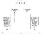
- the channel transfer function as measured in the direction opposite to the direction of an actual data transmission is affected by the transfer functions of the transmitting RF analog circuit of the receiver and of the receiving RF analog circuit of the transmitter. See Fig. 3.
- the calibration is more specifically described.
- h ij ' Transfer function of an i-th transmitting RF analog circuit of the receiver ⁇ Spatial transfer function ⁇ Transfer function of a j-th receiving RF analog circuit of the transmitter
- the transfer functions of respective analog circuits are different from one another, due to the manufacturing error and depending upon the temperature, for instance. Accordingly, in the sub-channel linking the j-th antenna of the transmitter and the i-th antenna of the receiver, the transfer function h ij in the forward direction (i.e., from the transmitter to the receiver) and the transfer function h ij ' in the reverse direction are different.
- both the transmitter and receiver performs the calibration for compensating the error in the characteristic of the transfer functions of the transmitting and receiving analog circuits, so that a correct transmit antenna weighting coefficient matrix V' can be derived from the channel information matrix H' of the reverse direction.
- the calibration referred to here corresponds to, for instance, a technique used for making the directivity in the downlink identical with that in the uplink in an adaptive array antennas, and is a method for compensating an error related to transmitting and receiving analog devices. It is known in the field that in the case of a device capable of 5GHz performance, once in a few hours is a sufficient frequency of the calibration.
- the transmitter performs the calibration at a frequency, e.g., once in a few hours, and holds the calibration coefficient.
- the receiver also performs the calibration once in a few hours and holds the calibration coefficient.
- the receiver When the reference signals or symbols for yielding the channel information matrix H' in the reverse direction, i.e. the channel information matrix of the uplink, is sent from the receiver to the transmitter, the receiver first implements the calibration using the calibration coefficient and sends the calibrated reference symbols.
- the transmitter implements the calibration using the calibration coefficient for the received reference symbols (see equation (9)) and performs the singular value decomposition of the channel information matrix H' constituted by the calibrated transfer functions, to obtain the transmit antenna weighting coefficient matrix V'.
- the transmitter and receiver independently perform the calibration.
- Fig. 4 schematically shows a structure of a communications apparatus having a plurality of antennas, focusing on the antennas and its vicinity.
- a transmitting analog circuit Tx1 and a receiving analog circuit Rx1 belong to an antenna #1. Since the characteristics of the respective analog circuits Tx and Rx are different from each other, the calibration is required.
- a coupler is provided on the output side of the transmitting analog circuit belonging to an antenna of one of a plurality of antenna systems or elements, so that a loopback path, as shown in Fig. 4, which is connected to a receiving analog circuit belonging to another antenna is made.
- a loopback transfer function is obtained as follows. As shown in Fig. 5, a coupler is provided on the output side of a transmitting analog circuit belonging to the antenna #2, to enable acquisition of the reverse loopback transfer function.
- the calibration coefficient is a ratio of the former transfer function to the latter one and expressed by the following equation:
- C i T 1 exp( j ⁇ 1 ) R i exp( j ⁇ i ) R 1 exp( j ⁇ 1 ) T i exp( j ⁇ i )
- the calibration coefficient of the transmitter is represented by CT(i) while the calibration coefficient of the receiver is represented by CR(i), where i indicates the antenna number.
- Step 0
- the transmitter obtains the calibration coefficient CT(j) with respect to the j-th antenna of the transmitter, while the receiver obtains the calibration coefficient CR(i) with respect to the i-th antenna of the receiver.
- the transmitter sends an OFDM symbol from each antenna j, by time division.
- the OFDM symbols are modulated by BPSK (Binary Phase Shift Keying).
- the receiver receives a reference signal for each antenna j from the transmitter, and calculates a transfer function h ij for each antenna pair or sub-channel.
- each of two antennas of the transmitter sends out the reference signal twice, and the signals are received by two antennas of the receiver.
- a total of four transfer functions can be obtained. That is, in the case of 2 ⁇ 2 MIMO transmission, a 2 ⁇ 2 channel information matrix H is obtained.
- the entry of the matrix H represents a transfer function having a value of a complex number.
- the receiver obtains a matrix U necessary when decoding the received signals, and a receive antenna weighting coefficient matrix U H for the decoding.
- the receiver sends out an OFDM symbol as a reference signal from each antenna i, by time division.
- the OFDM symbols are modulated by the BPSK.
- a reference signal sent from an antenna 0 is compensated by a calibration coefficient CR(0), while a reference signal sent from an antenna 1 is compensated by a calibration coefficient CR(1).
- the calibration coefficient is held in the form of a complex transfer function, the compensation is completed by multiplying the transmitted signal by the calibration coefficient.
- the transfer function expressed by the equation (9) can be made free from the influence of the variation related to the RF analog transmitting portion of the receiver.
- the transmitter receives a reference signal for each antenna i sent from the receiver, and calculates a transfer function h ij ' for each antenna pair or sub-channel.
- a reference signal received by the antenna 0 is compensated by the calibration coefficient CT(0), while a reference signal received by the antenna 1 is compensated by the calibration coefficient CT(1).
- CT(j) in the calibrating compensation, the transfer function expressed by the equation (9) can be made free from the influence of the variation related to the RF analog receiving portion of the transmitter. Then, the channel information matrix H' in the reverse direction is obtained from the transfer functions as compensated by the calibration.
- the transmitter weights a plurality of logically independent bit data by respective weighting vectors [w 1 , w 2 ] as entries of the transmit antenna weighting coefficient matrix V', and sends the weighted bit data out from the respective antennas, by space-time multiplexing.
- the receiver decodes the data or signals received by the respective antennas, with using the receive antenna weighting coefficient matrix U H .
- the transmitter and the receiver perform the calibration beforehand according to the processing procedure as described above.
- the weights used by the receiver are obtained on the basis of the obtained channel information matrix in regard to the direction from the transmitter to the receiver, while the weights required for data transmission by the transmitter are obtained by using the channel information matrix which is obtained by receiving from the receiver the reference signals as compensated by the calibration coefficient related to the receiver, and compensating the received reference signals by using the calibration coefficient related to the transmitter.
- the transmit antenna weighting coefficient matrix V which is directly obtained from the channel matrix H acquired in regard to the direction from the transmitter to the receiver, and the weighting coefficient matrix V' on the part of the transmitter which is directly obtained from the channel matrix H for the direction from the transmitter to the receiver, and the other transmit antenna weighting coefficient matrix V' obtained from H' acquired by the calibration based on the signals sent from the receiver to the transmitter do not in effect completely coincide with each other.
- Each of vectors of V is identical with a vector which corresponds to the counterpart of V' but each of whose components is rotated by an angle.
- the calibration coefficient is a value determined on the basis of a particular antenna as a reference, the value of the calibration coefficient is not an absolute value, but a relative calibration coefficient among a plurality of antenna elements.
- C i T 1 exp( j ⁇ 1 ) R i exp( j ⁇ i ) R 1 exp( j ⁇ 1 ) T i exp( j ⁇ i )
- the calibration coefficient of each antenna i is defined on the basis of the transfer functions of the transmitting and receiving analog portions of the antenna 1 as references.
- the calibration coefficient is not an absolute value directly derived from the transmission transfer function of the antenna i and the reception transfer function of the antenna i, but is a relative calibration coefficient.
- the calibration of antennas in a multi-antenna system is such a relative calibration. It is noted that the principle of the invention operates in combination with the relative calibration.
- the phase rotation mentioned above does not matter at all, in effect. This is because that the optimum transmit antenna weighting coefficient matrix V is always rotating equivalently, due to a slight clock error between the transmitting and receiving devices. That is, there is no point in having V and V' identical with each other, but it is sufficient to have every component of every vector of V as rotated by a same angle identical with the corresponding component of the corresponding vector of V'. Further, since V' and V are unitary matrices, the norm of each vector of V' is identical with the norm of corresponding vector of V.
Landscapes
- Engineering & Computer Science (AREA)
- Computer Networks & Wireless Communication (AREA)
- Signal Processing (AREA)
- Radio Transmission System (AREA)
- Mobile Radio Communication Systems (AREA)
Applications Claiming Priority (2)
| Application Number | Priority Date | Filing Date | Title |
|---|---|---|---|
| JP2003375504 | 2003-11-05 | ||
| JP2003375504 | 2003-11-05 |
Publications (3)
| Publication Number | Publication Date |
|---|---|
| EP1530305A2 true EP1530305A2 (fr) | 2005-05-11 |
| EP1530305A3 EP1530305A3 (fr) | 2005-06-15 |
| EP1530305B1 EP1530305B1 (fr) | 2017-01-04 |
Family
ID=34431275
Family Applications (1)
| Application Number | Title | Priority Date | Filing Date |
|---|---|---|---|
| EP04292628.7A Active EP1530305B1 (fr) | 2003-11-05 | 2004-11-05 | Système, procédé et dispositifs de communication sans fil |
Country Status (4)
| Country | Link |
|---|---|
| US (1) | US7680461B2 (fr) |
| EP (1) | EP1530305B1 (fr) |
| KR (1) | KR101083950B1 (fr) |
| CN (2) | CN100438369C (fr) |
Cited By (3)
| Publication number | Priority date | Publication date | Assignee | Title |
|---|---|---|---|---|
| WO2006138555A2 (fr) * | 2005-06-16 | 2006-12-28 | Qualcomm Incorporated | Mise en forme de faisceau a pseudo valeurs propres avec selection dynamique de faisceau |
| WO2007005858A2 (fr) * | 2005-06-30 | 2007-01-11 | Intel Corporation | Dispositif, systeme et procede d'elimination de la diaphonie |
| WO2007096820A1 (fr) * | 2006-02-22 | 2007-08-30 | Koninklijke Philips Electronics, N.V. | Système, appareil et procédé de formation de faisceaux asymétriques avec des émissions de puissance égale |
Families Citing this family (73)
| Publication number | Priority date | Publication date | Assignee | Title |
|---|---|---|---|---|
| JP4337507B2 (ja) * | 2003-11-05 | 2009-09-30 | ソニー株式会社 | 無線通信システム、並びに無線通信装置及び無線通信方法、並びにコンピュータ・プログラム |
| JP4604545B2 (ja) * | 2004-05-10 | 2011-01-05 | ソニー株式会社 | 無線通信システム、無線通信装置及び無線通信方法ム |
| JP4543737B2 (ja) * | 2004-05-10 | 2010-09-15 | ソニー株式会社 | 無線通信システム、無線通信装置及び無線通信方法、並びにコンピュータ・プログラム |
| US8457152B2 (en) * | 2004-07-16 | 2013-06-04 | Qualcomm Incorporated | Multiple modulation schemes in single rate layering wireless communication systems |
| DE602004028387D1 (de) * | 2004-12-13 | 2010-09-09 | Mitsubishi Electric Corp | Verfahren, System und Vorrichtung zur gleichmässig verteilten Datenübertragung in MIMO-Übertragungssystemen |
| KR100782925B1 (ko) * | 2004-12-15 | 2007-12-07 | 삼성전자주식회사 | 다중 안테나 통신 시스템 |
| US7719993B2 (en) * | 2004-12-30 | 2010-05-18 | Intel Corporation | Downlink transmit beamforming |
| JP4599192B2 (ja) * | 2005-03-02 | 2010-12-15 | 株式会社日立製作所 | 無線データ通信システム、および、無線データ通信方法 |
| WO2006112032A1 (fr) * | 2005-04-14 | 2006-10-26 | Matsushita Electric Industrial Co., Ltd. | Appareil de reception sans fil, appareil de transmission sans fil, systeme de communication sans fil, procede de reception sans fil, procede de transmission sans fil et procede de communication sans fil |
| CN100377515C (zh) * | 2005-07-14 | 2008-03-26 | 北京邮电大学 | 用于mimo-ofdm系统的自适应传输方法 |
| MY163773A (en) * | 2005-09-13 | 2017-10-31 | Taiwan Semiconductor Mfg Co Ltd | Position determination of mobile stations in a wireless network |
| JP4624901B2 (ja) * | 2005-10-12 | 2011-02-02 | 株式会社日立製作所 | 無線データ通信システム、無線データ通信方法および通信装置 |
| JP4832084B2 (ja) * | 2005-10-20 | 2011-12-07 | 三洋電機株式会社 | 通信方法ならびにそれを利用した無線装置および通信システム |
| US8340071B2 (en) * | 2005-10-26 | 2012-12-25 | Intel Corporation | Systems for communicating using multiple frequency bands in a wireless network |
| US20070099669A1 (en) * | 2005-10-26 | 2007-05-03 | Sadri Ali S | Communication signaling using multiple frequency bands in a wireless network |
| US7720036B2 (en) * | 2005-10-26 | 2010-05-18 | Intel Corporation | Communication within a wireless network using multiple frequency bands |
| US9084260B2 (en) | 2005-10-26 | 2015-07-14 | Intel Corporation | Systems for communicating using multiple frequency bands in a wireless network |
| US7653163B2 (en) * | 2005-10-26 | 2010-01-26 | Intel Corporation | Systems for communicating using multiple frequency bands in a wireless network |
| US9118111B2 (en) * | 2005-11-02 | 2015-08-25 | Qualcomm Incorporated | Antenna array calibration for wireless communication systems |
| US7853216B1 (en) | 2005-12-22 | 2010-12-14 | Atheros Communications, Inc. | Multi-channel RX/TX calibration and local oscillator mismatch mitigation |
| JP4752602B2 (ja) * | 2006-05-15 | 2011-08-17 | 株式会社日立製作所 | Mimo無線通信方法およびmimo無線通信装置 |
| KR100766322B1 (ko) | 2006-06-01 | 2007-10-11 | 한국전자통신연구원 | 다중 입출력 시스템에서의 송신기 및 데이터 송신 방법 |
| JP5032569B2 (ja) * | 2006-06-20 | 2012-09-26 | ホアウェイ・テクノロジーズ・カンパニー・リミテッド | プリコード化されたmimo−ofdmシステムにおいてフィードバック情報のオーバヘッドを低減させるための方法 |
| CN101656601B (zh) * | 2006-06-20 | 2014-09-17 | 华为技术有限公司 | 通信系统中反馈信息的方法、单元和处理器 |
| US7680205B2 (en) * | 2006-07-28 | 2010-03-16 | Broadcom Corporation | Method and system for transmitter beamforming for reduced complexity multiple input multiple output (MIMO) transceivers |
| CN1949691B (zh) * | 2006-09-28 | 2011-08-31 | 哈尔滨工业大学 | 一种mimo信道模拟器的控制方法及其实现装置 |
| JP4940867B2 (ja) * | 2006-09-29 | 2012-05-30 | 日本電気株式会社 | 移動通信システムにおける制御信号およびリファレンス信号の多重方法、リソース割当方法および基地局 |
| US7697959B2 (en) * | 2006-10-10 | 2010-04-13 | Intel Corporation | Adaptive multiple-antenna systems with omni-directional and sector-directional antenna modes |
| JP4840088B2 (ja) * | 2006-11-08 | 2011-12-21 | ソニー株式会社 | 無線通信システム、並びに無線通信装置及び無線通信方法 |
| US20080117865A1 (en) * | 2006-11-17 | 2008-05-22 | Li Guoqing C | Communication in a wireless network using multiple antennae |
| US7689171B2 (en) * | 2006-11-27 | 2010-03-30 | Intel Corporation | Reducing interference in a wireless network via antenna selection |
| EP2104981B1 (fr) * | 2006-12-01 | 2016-10-26 | Apple Inc. | Sélection d'antenne et démappage souple pour décodage mimo |
| CN101222259B (zh) * | 2007-01-09 | 2013-01-16 | 中兴通讯股份有限公司 | 用于4发射天线mimo系统的码本方式预编码方法 |
| KR20080077755A (ko) * | 2007-02-21 | 2008-08-26 | 삼성전자주식회사 | 다중 안테나 시스템에서 신호 보정 장치 및 방법 |
| JP5127269B2 (ja) * | 2007-03-07 | 2013-01-23 | キヤノン株式会社 | 無線通信装置、無線通信方法、当該無線通信方法をコンピュータに実行させるためのコンピュータプログラム |
| CN101291192B (zh) * | 2007-04-18 | 2012-01-11 | 中兴通讯股份有限公司 | 时分双工方式下下行多用户多输入多输出的预编码方法 |
| CN101321009B (zh) * | 2007-06-06 | 2012-12-19 | 中兴通讯股份有限公司 | 一种自适应mimo系统及其信号处理方法 |
| US8116698B2 (en) * | 2007-08-07 | 2012-02-14 | Cisco Technology, Inc. | Generalized MIMO-beamforming weight estimation |
| CN101471708B (zh) * | 2007-12-28 | 2012-09-05 | 华为技术有限公司 | 时分双工多输入多输出的下行波束形成方法、装置和系统 |
| JP4471006B2 (ja) * | 2008-02-04 | 2010-06-02 | ソニー株式会社 | 無線通信装置、アンテナ較正方法、およびプログラム |
| JP4561868B2 (ja) * | 2008-05-02 | 2010-10-13 | ソニー株式会社 | 無線通信装置、無線通信方法、コンピュータプログラム及び無線通信システム |
| JP4518184B2 (ja) * | 2008-05-02 | 2010-08-04 | ソニー株式会社 | 無線通信装置、無線通信方法、無線通信システム及びコンピュータプログラム |
| JP4544349B2 (ja) * | 2008-07-14 | 2010-09-15 | ソニー株式会社 | 無線通信装置及び無線通信方法、並びにコンピュータ・プログラム |
| JP4605266B2 (ja) * | 2008-07-23 | 2011-01-05 | ソニー株式会社 | 無線通信システム、無線通信装置及び無線通信方法、エンコード装置及びエンコード方法、並びにコンピュータ・プログラム |
| KR20100034838A (ko) * | 2008-09-25 | 2010-04-02 | 삼성전자주식회사 | 다중안테나 통신시스템에서 중계기를 지원하기 위한 보정 장치 및 방법 |
| US8321488B2 (en) * | 2008-11-04 | 2012-11-27 | Mediatek Inc. | Singular value decomposing method and related singular value decomposing device |
| CN101547036B (zh) | 2009-01-23 | 2012-08-08 | 华为技术有限公司 | 一种发射天线扩展后的参考信号发送方法、设备和系统 |
| CN101615982A (zh) * | 2009-07-17 | 2009-12-30 | 中兴通讯股份有限公司 | 分组干扰抑制方法及装置 |
| JP5540592B2 (ja) | 2009-07-23 | 2014-07-02 | ソニー株式会社 | 通信システム、通信制御方法、移動端末、および中継装置 |
| JP5909843B2 (ja) | 2009-08-10 | 2016-04-27 | ソニー株式会社 | 通信システム、通信装置及び通信方法、並びにコンピューター・プログラム |
| JP2011066874A (ja) | 2009-08-17 | 2011-03-31 | Sony Corp | 通信システム、通信装置及び通信方法、並びにコンピューター・プログラム |
| JP2011071963A (ja) | 2009-08-26 | 2011-04-07 | Sony Corp | 通信システム、通信装置及び通信方法、並びにコンピューター・プログラム |
| KR101587566B1 (ko) | 2009-12-30 | 2016-02-02 | 삼성전자주식회사 | 다중 사용자 다중 안테나 시스템에서의 유니터리 프리코딩 장치 및 방법 |
| CN102223171B (zh) * | 2011-06-17 | 2014-01-01 | 电信科学技术研究院 | 一种信道信息获取和反馈方法、系统及装置 |
| US9448970B2 (en) | 2013-06-14 | 2016-09-20 | Microsoft Technology Licensing, Llc | Singular value decomposition of complex matrix |
| US9379791B2 (en) * | 2014-08-01 | 2016-06-28 | Qualcomm Incorporated | Multiple input multiple output (MIMO) communication systems and methods for chip to chip and intrachip communication |
| US9319113B2 (en) | 2014-09-19 | 2016-04-19 | Qualcomm Incorporated | Simplified multiple input multiple output (MIMO) communication schemes for interchip and intrachip communications |
| JP2016195331A (ja) * | 2015-03-31 | 2016-11-17 | 三星電子株式会社Samsung Electronics Co.,Ltd. | アレーアンテナ送受信装置及び校正値算出方法 |
| CN112671687B (zh) * | 2015-07-23 | 2024-04-05 | 三星电子株式会社 | 发送方法和接收方法 |
| CN106685495A (zh) * | 2015-11-05 | 2017-05-17 | 索尼公司 | 无线通信方法和无线通信设备 |
| US9847802B1 (en) * | 2016-08-16 | 2017-12-19 | Xilinx, Inc. | Reconfiguration of single-band transmit and receive paths to multi-band transmit and receive paths in an integrated circuit |
| US9991972B1 (en) * | 2017-04-26 | 2018-06-05 | Cisco Technology, Inc. | Remote radio head calibration |
| CN108199726B (zh) * | 2018-03-16 | 2020-08-28 | Oppo广东移动通信有限公司 | 多路选择开关及相关产品 |
| US10644771B2 (en) * | 2018-06-08 | 2020-05-05 | University Of South Florida | Using artificial signals to maximize capacity and secrecy of multiple-input multiple-output (MIMO) communication |
| US10516452B1 (en) * | 2018-06-08 | 2019-12-24 | University Of South Florida | Using artificial signals to maximize capacity and secrecy of multiple-input multiple-output (MIMO) communication |
| US10622003B2 (en) * | 2018-07-12 | 2020-04-14 | Intel IP Corporation | Joint beamforming and echo cancellation for reduction of noise and non-linear echo |
| WO2020014825A1 (fr) * | 2018-07-16 | 2020-01-23 | Nokia Shanghai Bell Co., Ltd. | Traitement de signaux de référence au cours d'un précodage |
| CN110830202B (zh) * | 2018-08-10 | 2022-02-25 | 华为技术有限公司 | 通信方法、装置和通信系统 |
| CN113381789B (zh) * | 2020-03-09 | 2022-11-01 | 中国移动通信集团设计院有限公司 | 一种多输入多输出数据天线的物理层信道处理方法及装置 |
| CN112910521B (zh) * | 2021-02-27 | 2022-04-05 | 中电万维信息技术有限责任公司 | 一种基于深度学习的mimo混合波束赋形方法 |
| US11777567B2 (en) * | 2021-04-30 | 2023-10-03 | Aptiv Technologies Limited | Independent transmit and receive channel calibration for multiple-input multiple-output (MIMO) systems |
| WO2023027695A1 (fr) * | 2021-08-24 | 2023-03-02 | Zeku, Inc. | Appareil et procédé de détermination de fonctions de transfert pour estimation de position |
| JP2023037446A (ja) * | 2021-09-03 | 2023-03-15 | 日本電気株式会社 | 無線受信装置及びその方法 |
Citations (4)
| Publication number | Priority date | Publication date | Assignee | Title |
|---|---|---|---|---|
| US6058105A (en) * | 1997-09-26 | 2000-05-02 | Lucent Technologies Inc. | Multiple antenna communication system and method thereof |
| US20030130003A1 (en) * | 2002-01-04 | 2003-07-10 | Lg Electronics Inc. | Method and apparatus of allocating power in multiple-input multiple-output communication system |
| WO2003069816A2 (fr) * | 2002-02-13 | 2003-08-21 | Witcom Ltd. | Mulitplexage spatial en champ proche |
| EP1940098A1 (fr) * | 2002-12-11 | 2008-07-02 | Qualcomm Incorporated | Dérivation de vecteurs propres pour traitement spatial dans des systèmes de communication mimo |
Family Cites Families (13)
| Publication number | Priority date | Publication date | Assignee | Title |
|---|---|---|---|---|
| US5936569A (en) | 1997-12-02 | 1999-08-10 | Nokia Telecommunications Oy | Method and arrangement for adjusting antenna pattern |
| JP2001053661A (ja) | 1999-08-09 | 2001-02-23 | Kyocera Corp | アダプティブアレイ基地局における送受信系調整方法およびアダプティブアレイ無線装置 |
| JP3567976B2 (ja) * | 2000-03-07 | 2004-09-22 | 日本電気株式会社 | アレーアンテナ受信装置 |
| US20030031264A1 (en) * | 2001-08-07 | 2003-02-13 | Barry John R. | System and method for adaptive channel diagonalization for array-to-array wireless communications |
| JP2003060557A (ja) | 2001-08-10 | 2003-02-28 | Fujitsu Ltd | アレーアンテナシステムを有する基地局 |
| US6760388B2 (en) | 2001-12-07 | 2004-07-06 | Qualcomm Incorporated | Time-domain transmit and receive processing with channel eigen-mode decomposition for MIMO systems |
| JP2003264492A (ja) | 2002-03-08 | 2003-09-19 | Sony Corp | 無線通信装置およびアレイアンテナの特性調整方法 |
| KR100464014B1 (ko) * | 2002-03-21 | 2004-12-30 | 엘지전자 주식회사 | 다중 입출력 이동 통신 시스템에서의 폐루프 신호 처리 방법 |
| ATE421809T1 (de) * | 2002-08-22 | 2009-02-15 | Imec Inter Uni Micro Electr | Verfahren zur mimo-übertragung für mehrere benutzer und entsprechende vorrichtungen |
| US8208364B2 (en) * | 2002-10-25 | 2012-06-26 | Qualcomm Incorporated | MIMO system with multiple spatial multiplexing modes |
| US8320301B2 (en) * | 2002-10-25 | 2012-11-27 | Qualcomm Incorporated | MIMO WLAN system |
| US7986742B2 (en) | 2002-10-25 | 2011-07-26 | Qualcomm Incorporated | Pilots for MIMO communication system |
| US20040192218A1 (en) * | 2003-03-31 | 2004-09-30 | Oprea Alexandru M. | System and method for channel data transmission in wireless communication systems |
-
2004
- 2004-09-22 US US10/946,074 patent/US7680461B2/en active Active
- 2004-11-04 KR KR1020040089333A patent/KR101083950B1/ko active IP Right Grant
- 2004-11-04 CN CNB2004100905912A patent/CN100438369C/zh active Active
- 2004-11-04 CN CN200810002700.9A patent/CN101232318B/zh active Active
- 2004-11-05 EP EP04292628.7A patent/EP1530305B1/fr active Active
Patent Citations (4)
| Publication number | Priority date | Publication date | Assignee | Title |
|---|---|---|---|---|
| US6058105A (en) * | 1997-09-26 | 2000-05-02 | Lucent Technologies Inc. | Multiple antenna communication system and method thereof |
| US20030130003A1 (en) * | 2002-01-04 | 2003-07-10 | Lg Electronics Inc. | Method and apparatus of allocating power in multiple-input multiple-output communication system |
| WO2003069816A2 (fr) * | 2002-02-13 | 2003-08-21 | Witcom Ltd. | Mulitplexage spatial en champ proche |
| EP1940098A1 (fr) * | 2002-12-11 | 2008-07-02 | Qualcomm Incorporated | Dérivation de vecteurs propres pour traitement spatial dans des systèmes de communication mimo |
Cited By (6)
| Publication number | Priority date | Publication date | Assignee | Title |
|---|---|---|---|---|
| WO2006138555A2 (fr) * | 2005-06-16 | 2006-12-28 | Qualcomm Incorporated | Mise en forme de faisceau a pseudo valeurs propres avec selection dynamique de faisceau |
| WO2006138555A3 (fr) * | 2005-06-16 | 2007-03-08 | Qualcomm Inc | Mise en forme de faisceau a pseudo valeurs propres avec selection dynamique de faisceau |
| WO2007005858A2 (fr) * | 2005-06-30 | 2007-01-11 | Intel Corporation | Dispositif, systeme et procede d'elimination de la diaphonie |
| WO2007005858A3 (fr) * | 2005-06-30 | 2007-06-28 | Intel Corp | Dispositif, systeme et procede d'elimination de la diaphonie |
| WO2007096820A1 (fr) * | 2006-02-22 | 2007-08-30 | Koninklijke Philips Electronics, N.V. | Système, appareil et procédé de formation de faisceaux asymétriques avec des émissions de puissance égale |
| US8190211B2 (en) | 2006-02-22 | 2012-05-29 | Koninklijke Philips Electronics N.V. | System, apparatus, and method for asymmetrical beamforming with equal-power transmissions |
Also Published As
| Publication number | Publication date |
|---|---|
| CN101232318B (zh) | 2016-01-20 |
| CN1614906A (zh) | 2005-05-11 |
| CN100438369C (zh) | 2008-11-26 |
| EP1530305A3 (fr) | 2005-06-15 |
| KR20050043670A (ko) | 2005-05-11 |
| US7680461B2 (en) | 2010-03-16 |
| US20050095996A1 (en) | 2005-05-05 |
| EP1530305B1 (fr) | 2017-01-04 |
| CN101232318A (zh) | 2008-07-30 |
| KR101083950B1 (ko) | 2011-11-16 |
Similar Documents
| Publication | Publication Date | Title |
|---|---|---|
| US10673655B2 (en) | Wireless communications system, wireless communications apparatus, wireless communications method and computer program for wireless communication | |
| US7680461B2 (en) | Wireless communications system, wireless communications method, and wireless communications apparatus | |
| US11664880B2 (en) | Beamforming for non-collaborative, space division multiple access systems | |
| KR101336180B1 (ko) | 무선 통신 시스템, 무선 통신 장치 및 무선 통신 방법 | |
| US7167526B2 (en) | Wireless communication apparatus and method | |
| JP4924106B2 (ja) | 無線通信システム、並びに無線通信装置及び無線通信方法 | |
| US20050141631A1 (en) | Wireless communication system, wireless communication device and wireless communication method, and computer program thereof | |
| US7627045B2 (en) | System, method, apparatus, and computer program for wireless communication | |
| JP4039413B2 (ja) | 無線通信システム及び無線通信方法、並びに無線通信装置 | |
| EP1379020A1 (fr) | Appareil et méthode de communication sans fils | |
| KR101098215B1 (ko) | 무선 통신 시스템, 무선 통신 장치 및 무선 통신 방법, 및 기록 매체 |
Legal Events
| Date | Code | Title | Description |
|---|---|---|---|
| PUAI | Public reference made under article 153(3) epc to a published international application that has entered the european phase |
Free format text: ORIGINAL CODE: 0009012 |
|
| PUAL | Search report despatched |
Free format text: ORIGINAL CODE: 0009013 |
|
| AK | Designated contracting states |
Kind code of ref document: A2 Designated state(s): AT BE BG CH CY CZ DE DK EE ES FI FR GB GR HU IE IS IT LI LU MC NL PL PT RO SE SI SK TR |
|
| AX | Request for extension of the european patent |
Extension state: AL HR LT LV MK YU |
|
| AK | Designated contracting states |
Kind code of ref document: A3 Designated state(s): AT BE BG CH CY CZ DE DK EE ES FI FR GB GR HU IE IS IT LI LU MC NL PL PT RO SE SI SK TR |
|
| AX | Request for extension of the european patent |
Extension state: AL HR LT LV MK YU |
|
| 17P | Request for examination filed |
Effective date: 20051206 |
|
| AKX | Designation fees paid |
Designated state(s): DE FR GB |
|
| 17Q | First examination report despatched |
Effective date: 20090702 |
|
| GRAP | Despatch of communication of intention to grant a patent |
Free format text: ORIGINAL CODE: EPIDOSNIGR1 |
|
| RIC1 | Information provided on ipc code assigned before grant |
Ipc: H04B 7/04 20060101ALI20160601BHEP Ipc: H04B 7/06 20060101AFI20160601BHEP Ipc: H04L 1/06 20060101ALI20160601BHEP Ipc: H04B 7/08 20060101ALI20160601BHEP |
|
| INTG | Intention to grant announced |
Effective date: 20160620 |
|
| GRAS | Grant fee paid |
Free format text: ORIGINAL CODE: EPIDOSNIGR3 |
|
| GRAA | (expected) grant |
Free format text: ORIGINAL CODE: 0009210 |
|
| AK | Designated contracting states |
Kind code of ref document: B1 Designated state(s): DE FR GB |
|
| REG | Reference to a national code |
Ref country code: GB Ref legal event code: FG4D |
|
| REG | Reference to a national code |
Ref country code: DE Ref legal event code: R081 Ref document number: 602004050603 Country of ref document: DE Owner name: WI-FI ONE TECHNOLOGIES INTERNATIONAL LIMITED, IE Free format text: FORMER OWNER: SONY CORPORATION, TOKIO/TOKYO, JP |
|
| REG | Reference to a national code |
Ref country code: DE Ref legal event code: R096 Ref document number: 602004050603 Country of ref document: DE |
|
| REG | Reference to a national code |
Ref country code: DE Ref legal event code: R097 Ref document number: 602004050603 Country of ref document: DE |
|
| PLBE | No opposition filed within time limit |
Free format text: ORIGINAL CODE: 0009261 |
|
| STAA | Information on the status of an ep patent application or granted ep patent |
Free format text: STATUS: NO OPPOSITION FILED WITHIN TIME LIMIT |
|
| REG | Reference to a national code |
Ref country code: FR Ref legal event code: PLFP Year of fee payment: 14 |
|
| 26N | No opposition filed |
Effective date: 20171005 |
|
| REG | Reference to a national code |
Ref country code: DE Ref legal event code: R081 Ref document number: 602004050603 Country of ref document: DE Owner name: WI-FI ONE TECHNOLOGIES INTERNATIONAL LIMITED, IE Free format text: FORMER OWNER: SONY CORPORATION, TOKYO, JP |
|
| REG | Reference to a national code |
Ref country code: GB Ref legal event code: 732E Free format text: REGISTERED BETWEEN 20190124 AND 20190130 |
|
| PGFP | Annual fee paid to national office [announced via postgrant information from national office to epo] |
Ref country code: GB Payment date: 20231127 Year of fee payment: 20 |
|
| PGFP | Annual fee paid to national office [announced via postgrant information from national office to epo] |
Ref country code: FR Payment date: 20231127 Year of fee payment: 20 Ref country code: DE Payment date: 20231129 Year of fee payment: 20 |