EP1530271B1 - Dispositif de soudage des brins de torons - Google Patents
Dispositif de soudage des brins de torons Download PDFInfo
- Publication number
- EP1530271B1 EP1530271B1 EP04026242A EP04026242A EP1530271B1 EP 1530271 B1 EP1530271 B1 EP 1530271B1 EP 04026242 A EP04026242 A EP 04026242A EP 04026242 A EP04026242 A EP 04026242A EP 1530271 B1 EP1530271 B1 EP 1530271B1
- Authority
- EP
- European Patent Office
- Prior art keywords
- cheeks
- compression space
- jaws
- welding
- lower electrode
- Prior art date
- Legal status (The legal status is an assumption and is not a legal conclusion. Google has not performed a legal analysis and makes no representation as to the accuracy of the status listed.)
- Not-in-force
Links
Images

Classifications
-
- H—ELECTRICITY
- H01—ELECTRIC ELEMENTS
- H01R—ELECTRICALLY-CONDUCTIVE CONNECTIONS; STRUCTURAL ASSOCIATIONS OF A PLURALITY OF MUTUALLY-INSULATED ELECTRICAL CONNECTING ELEMENTS; COUPLING DEVICES; CURRENT COLLECTORS
- H01R43/00—Apparatus or processes specially adapted for manufacturing, assembling, maintaining, or repairing of line connectors or current collectors or for joining electric conductors
- H01R43/02—Apparatus or processes specially adapted for manufacturing, assembling, maintaining, or repairing of line connectors or current collectors or for joining electric conductors for soldered or welded connections
- H01R43/0214—Resistance welding
-
- B—PERFORMING OPERATIONS; TRANSPORTING
- B23—MACHINE TOOLS; METAL-WORKING NOT OTHERWISE PROVIDED FOR
- B23K—SOLDERING OR UNSOLDERING; WELDING; CLADDING OR PLATING BY SOLDERING OR WELDING; CUTTING BY APPLYING HEAT LOCALLY, e.g. FLAME CUTTING; WORKING BY LASER BEAM
- B23K11/00—Resistance welding; Severing by resistance heating
- B23K11/002—Resistance welding; Severing by resistance heating specially adapted for particular articles or work
-
- B—PERFORMING OPERATIONS; TRANSPORTING
- B23—MACHINE TOOLS; METAL-WORKING NOT OTHERWISE PROVIDED FOR
- B23K—SOLDERING OR UNSOLDERING; WELDING; CLADDING OR PLATING BY SOLDERING OR WELDING; CUTTING BY APPLYING HEAT LOCALLY, e.g. FLAME CUTTING; WORKING BY LASER BEAM
- B23K2101/00—Articles made by soldering, welding or cutting
- B23K2101/32—Wires
Definitions
- the invention relates to a device for welding the wires of one or more, in particular made of copper strands, also tinned strands, to a solid and gas-tight connection node, with a compression space for at least one inserted strand section, wherein the flanks of the compression chamber as with ceramic plates in the field, in their direction against each other adjustable jaws are executed, and the horizontal boundary of the compression space are formed by the end faces of a lower electrode and an upper electrode.
- connection node proves to be gas-tight and only offers its surroundings its outer surfaces, so that oxidation processes are deprived of essential contact surfaces.
- the generic EP 0 517 040 A1 discloses a device for welding the wires of strands, which also requires exactly operating and thus expensive drives in order to be able to set the compression space to the desired level. Again, necessary for the adjustment of the compression space control devices make the device for welding expensive.
- the invention has for its object to propose a convenient device for welding the wires of strands, by means of which also fasteners can be welded to the strands.
- the jaws drive only against a predetermined electrode and are applied here form-fitting, no complicated, precise and thus expensive drive is required.
- the positive engagement of the jaws on the electrode ensures that no wires of the strand can get between the jaws and the lower electrode, so that all wires of the strand can be compacted and welded together.
- the upper electrode is also form-fitting on the jaws, so that all cores of the strand remain safely in the compression space and are here subjected to the welding process.
- the height of the compression chamber could be adjusted by means of separate adjusting drives which act on the jaws, it has been proven that the jaws are held in their upper position of the vertical guide by spring elements and that the positioning device of the upper electrode supports the jaws against the jaws Force the springs can bring in the desired operating position.
- the connecting elements such as. B. the ground connector
- the connecting elements have an area that is intended for connection to the other wire after connection with the strand.
- Ground connectors have to For this purpose, often an eyelet, which later serves to receive a connecting screw.
- the tool can z. B. have a holder for a corresponding eyelet, which holds the ground connector outside of the welding electrode area and the area to be welded of the ground connector in the region of the above-open compression space can protrude.
- the device still has a stamp which can be brought to bear on the connection elements held in the tool in the region outside the stripped stranded sections inserted in the compression space, then the noses of the connecting element serving as strain relief can take place in an immediately subsequent to the welding operation, taking place in the same working step Crimping be wrapped around the insulation of the strand.
- the device is assigned to a control or regulating device, via which the size of the lower electrode and / or the vertical setting position of the jaws and / or the welding current and / or the control of the punch can be predetermined and depending on the strand to be welded / or is controllable.
- the control or regulating device can thus predetermine a sub electrode which is as favorable as possible, and can possibly effect the positioning position of the jaws as well as the welding current and the activation of the stamp.
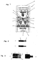
- Figure 1 shows a device 1 for welding the wires 2, a strand 3.
- the device 1 comprises a support 4 for a plurality of e.g. arranged one behind the other sub-electrodes 5.
- the various sub-electrodes 5 can optionally be clamped between the jaws 6, 6 'which are covered with ceramic plates.
- the jaws have drive devices 7, 7 ', by means of which the jaws 6, 6' can be moved horizontally against the flanks of the lower electrode 5.
- the lower part of a compression space 8 is formed, in which the wires 2 of a stranded wire 3 are inserted. It is quite possible here to introduce a multiplicity of strands 3, 3 ', 3 "into the compression space 8.
- an upper electrode 9 is shown, which by means of a drive 10 against the jaws 6, 6' can be adjusted.
- the jaws 6, 6 ' are by means of guides 16, 16' vertically adjustable, and are held by spring elements 11 in its upper position. Due to the force of the drive 10, the spring elements can be compressed to a predeterminable degree.
- the predeterminable dimension predetermines the height of the compression space 8.
- the lower electrode 5 and the upper electrode 9 are provided with electric terminals not shown. After the jaws 6, 6 'have moved together and the top electrode 9 have been pressed onto the wires 2 of the strand 3, the A are the compacted accordingly. If now the welding current is switched on, the copper electrode, if necessary also tinned copper wires, can be welded together.
- FIG. 2 a shows the stranded wire 3 with the wires 2 before insertion into the compression space 8.
- FIG. 2 b shows the stranded wire 3 with compacted and welded-together wires 2.
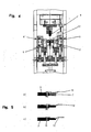
- FIG. 4 shows the device 1 according to FIG. 1, but in the region of the upwardly facing end faces of the jaws 6, 6 ', a connecting element 12 is held in a tool (not shown) located in front of the cutting plane.
- the upper electrode 9 is approached against the jaws 6, 6 '.
- the connecting element 12 is pressed down on the wires 2, which are compacted by the contact force of the drive 10. Now, when the welding current is turned on, the compacted wires are welded together and with the connecting element 2.
- FIG. 5a shows the initial situation as indicated in FIG. 4, while FIG. 5b shows the welded wires and the connecting element 12 welded to the wires.
- FIG. 6 behind the plane shown in FIGS. 1 and 4 there is a punch 13, 13 'according to the invention, whose tools 14, 14' rest on the jaws 6, 6 'and the connecting element 12 after welding of the ground connector , can be moved together. As a result, serve as a strain relief 15 flags around the Insulation of the strand 3 crimped.
- FIG. 5c shows the finished stranded wire 3, in which the wires 2 are compacted and welded and additionally welded to the connecting element 12 and in which the strain relief is crimped around the insulation of the stranded wire 3.
Landscapes
- Engineering & Computer Science (AREA)
- Manufacturing & Machinery (AREA)
- Mechanical Engineering (AREA)
- Manufacturing Of Electrical Connectors (AREA)
- Resistance Welding (AREA)
- Manufacture Of Motors, Generators (AREA)
Claims (6)
- Dispositif (1) pour souder les brins (2, 2', 2") d'un ou de plusieurs torons (3, 3', 3") consistant notamment en cuivre, également de torons étamés (3, 3', 3") en un noeud de jonction fixe et étanche au gaz, avec une chambre de compression (8), pour au moins un tronçon de toron inséré, les flancs de la chambre de compression (8) étant réalisés sous la forme de mâchoires (6, 6') doublées de plaques en céramique, susceptibles d'être mises en prise l'une contre l'autre dans leur direction, et la délimitation horizontale de la chambre de compression (8) étant formée par les surfaces frontales d'une électrode inférieure (5) et d'une électrode supérieure (9),
caractérisé en ce que les mâchoires (6, 6') sont susceptibles d'être mises en prise contre des flancs opposés de l'électrode inférieure (5) et sont capables de réceptionner entre elles par complémentarité de forme la surface frontale de l'électrode inférieure (5), en ce que respectivement des guidages verticaux (16, 16'), par l'intermédiaire desquels la hauteur de la chambre de compression (8) est réglable sont associés aux mâchoires et en ce que la surface frontale de l'électrode supérieure (9) est susceptible d'être mise en prise contre les mâchoires (6, 6') et est susceptible de s'appuyer sur les surfaces frontales dirigées vers le haut des mâchoires (6, 6'). - Dispositif selon la revendication 1, caractérisé en ce qu'on a prévu au moins deux électrodes inférieures (5) de dimensions différentes, qui sont positionnables au choix entre les mâchoires (6, 6').
- Dispositif selon la revendication 1 ou 2, caractérisé en ce que les mâchoires (6, 6') sont maintenues sous l'effet d'éléments à ressorts (11) dans la position supérieure du guidage vertical (16, 16') et en ce que le dispositif de mise en prise (10) de l'électrode supérieure (9) est capable d'amener les mâchoires (6, 6') dans la position active verticale souhaitée, à l'encontre de la force des éléments à ressorts (11).
- Dispositif selon l'une quelconque des revendications 1 à 3, caractérisé en ce qu'un outil capable de maintenir des éléments de liaison (12), tels que par exemple des bornes de mise à la masse, susceptibles d'être soudés avec le au moins un toron (3, 3', 3") est associé aux mâchoires (6,6').
- Dispositif selon la revendication 4, caractérisé en ce que le dispositif comporte un poinçon (13, 13') qui dans la région extérieure des brins (2) dénudés, insérés dans la chambre de compression (8) est susceptible d'être amené en action sur des éléments de liaison (12) maintenus dans l'outil.
- Dispositif selon l'une quelconque des revendications 1 à 5, caractérisé en ce qu'un dispositif de commande ou de réglage, par l'intermédiaire duquel, en fonction du toron à souder (3, 3', 3"), la dimension de l'électrode inférieure (5) et/ou la position de mise en prise verticale des mâchoires (6, 6') et ou le courant de soudage et/ou l'activation du poinçon (13, 13') sont prédéfinissables et/ou réglables est associé au dispositif (1).
Applications Claiming Priority (2)
| Application Number | Priority Date | Filing Date | Title |
|---|---|---|---|
| DE10352482 | 2003-11-07 | ||
| DE10352482A DE10352482A1 (de) | 2003-11-07 | 2003-11-07 | Vorrichtung zum Verschweißen der Adern von Litzen |
Publications (2)
| Publication Number | Publication Date |
|---|---|
| EP1530271A1 EP1530271A1 (fr) | 2005-05-11 |
| EP1530271B1 true EP1530271B1 (fr) | 2007-03-07 |
Family
ID=34428654
Family Applications (1)
| Application Number | Title | Priority Date | Filing Date |
|---|---|---|---|
| EP04026242A Not-in-force EP1530271B1 (fr) | 2003-11-07 | 2004-11-05 | Dispositif de soudage des brins de torons |
Country Status (3)
| Country | Link |
|---|---|
| EP (1) | EP1530271B1 (fr) |
| AT (1) | ATE356452T1 (fr) |
| DE (2) | DE10352482A1 (fr) |
Families Citing this family (8)
| Publication number | Priority date | Publication date | Assignee | Title |
|---|---|---|---|---|
| DE102007032584B4 (de) * | 2006-07-12 | 2008-11-13 | Maschinen- Und Apparatevertrieb Helmut Strunk | Vorrichtung zum Schweißen einer Litze an einen Kontakt |
| ATE522309T1 (de) | 2007-10-11 | 2011-09-15 | Resistronic Ag | Kompaktiervorrichtung zum kompaktieren von abschnitten von litzkabeln |
| DE102010035424A1 (de) | 2010-08-26 | 2012-03-01 | Audi Ag | Verfahren zum Verbinden eines elektrischen Leiters mit einem elektrischen Kontaktteil |
| DE102013010981B3 (de) * | 2013-07-01 | 2014-08-28 | Audi Ag | Verfahren und Vorrichtung zum Verbinden eines elektrischen Leiters mit einem elektrischen Kontaktteil |
| DE102016103039B3 (de) * | 2016-02-22 | 2017-08-03 | Lisa Dräxlmaier GmbH | Vorrichtung zum Formen eines Endes einer Leitung und Verfahren |
| DE102016105227B4 (de) | 2016-03-21 | 2021-10-28 | Lisa Dräxlmaier GmbH | Verbindungsvorrichtung, Verbindungsverfahren, Kontaktelement und Steckergehäuse |
| TWI648121B (zh) * | 2017-10-27 | 2019-01-21 | 萬旭電業股份有限公司 | 拉錫線銲接機控制方法 |
| CN113814545B (zh) * | 2021-09-18 | 2023-03-03 | 广州微点焊设备有限公司 | 显微电阻焊点焊机头及其对预设定电极力的自检测方法 |
Family Cites Families (3)
| Publication number | Priority date | Publication date | Assignee | Title |
|---|---|---|---|---|
| GB1511700A (en) * | 1975-12-23 | 1978-05-24 | Rosemount Eng Co Ltd | Apparatus and method for welding electrical wire or cable |
| DE4117696C1 (fr) * | 1991-05-30 | 1992-10-22 | Maschinen- Und Apparatevertrieb Helmut Strunk, 5242 Kirchen, De | |
| FR2680436B1 (fr) * | 1991-08-12 | 1995-05-19 | Technax | Procede de fabrication de tresses conductrices pour appareillages electro-mecaniques et dispositif de mise en óoeuvre. |
-
2003
- 2003-11-07 DE DE10352482A patent/DE10352482A1/de not_active Withdrawn
-
2004
- 2004-11-05 AT AT04026242T patent/ATE356452T1/de active
- 2004-11-05 DE DE502004003114T patent/DE502004003114D1/de active Active
- 2004-11-05 EP EP04026242A patent/EP1530271B1/fr not_active Not-in-force
Also Published As
| Publication number | Publication date |
|---|---|
| ATE356452T1 (de) | 2007-03-15 |
| DE502004003114D1 (de) | 2007-04-19 |
| EP1530271A1 (fr) | 2005-05-11 |
| DE10352482A1 (de) | 2005-06-23 |
Similar Documents
| Publication | Publication Date | Title |
|---|---|---|
| DE102005048368B3 (de) | Verfahren zum Herstellen einer Schweißverbindung zwischen elektrischen Leitern | |
| DE102008003961B4 (de) | Vorrichtung und Verfahren zum Crimpen eines Anschlussstücks | |
| EP1530271B1 (fr) | Dispositif de soudage des brins de torons | |
| DE19840214C2 (de) | Verfahren und Vorrichtung zum Preßschweißen eines Anschlußstücks | |
| EP3236544A1 (fr) | Dispositif et procédé de regroupement de conduites individuelles d'un faisceau de câbles | |
| DE1615659C3 (de) | Verfahren und Vorrichtung zum elektrischen Verbinden einzelner Leitungsdrähte einer Gruppe von Leitugsdrähten | |
| DE3942276C2 (fr) | ||
| DE102004044480A1 (de) | Verfahren zur Herstellung einer Schweißverbindung sowie Schweißverbindung | |
| DE102007032584B4 (de) | Vorrichtung zum Schweißen einer Litze an einen Kontakt | |
| DE3933316C2 (fr) | ||
| DE69711796T2 (de) | Verfahren zur Herstellung eines Kabelbaumes | |
| EP4188632A1 (fr) | Procédé de soudage en plusieurs étapes de noeuds au moyen d'un dispositif de soudage par ultrasons, et faisceau de conducteurs correspondant | |
| EP3520179B1 (fr) | Dispositif, procédé et système de sertissage inverse | |
| EP3474391A1 (fr) | Procédé de raccordement d'au moins deux fils à plusieurs brins au moyen d'ultrasons | |
| EP0474113A1 (fr) | Dispositif de connexion pour câbles multifilaires | |
| DE1615682B1 (de) | Elektrische Klemmverbindung fuer Doppeladern und ein Verfahren zur Herstellung einer derartigen Klemmverbindung | |
| DE10218214A1 (de) | Schraubklemme zum Klemmen von isolierten und abisolierten elektrischen Leitern | |
| DE9315914U1 (de) | Steckkontaktsatz für eine steckbare elektrische Anschlußeinrichtung für den Elektromotor einer Heizungspumpe | |
| DE4117697A1 (de) | Vorrichtung zum verschweissen der adern von litzen, insbesondere kupferlitzen | |
| DE2201883A1 (de) | Kontaktbuchse fuer elektrische installationsgeraete | |
| DE4241955C2 (de) | Werkzeugaufnahme | |
| DE10155924A1 (de) | Vorrichtung zum Verbinden für zwei elektrische Kabel | |
| DE4034950B4 (de) | Anschließvorrichtung zum Anschließen von elektrischen Leitungsdrähten | |
| DE19900137C2 (de) | Kabelstruktur aus Draht und Verkabelungsverfahren | |
| DE1615682C (de) | Elektrische Klemmverbindung für Doppeladern und ein Verfahren zur Herstellung einer derartigen Klemmverbindung |
Legal Events
| Date | Code | Title | Description |
|---|---|---|---|
| PUAI | Public reference made under article 153(3) epc to a published international application that has entered the european phase |
Free format text: ORIGINAL CODE: 0009012 |
|
| AK | Designated contracting states |
Kind code of ref document: A1 Designated state(s): AT BE BG CH CY CZ DE DK EE ES FI FR GB GR HU IE IS IT LI LU MC NL PL PT RO SE SI SK TR |
|
| AX | Request for extension of the european patent |
Extension state: AL HR LT LV MK YU |
|
| 17P | Request for examination filed |
Effective date: 20051024 |
|
| AKX | Designation fees paid |
Designated state(s): AT BE BG CH CY CZ DE DK EE ES FI FR GB GR HU IE IS IT LI LU MC NL PL PT RO SE SI SK TR |
|
| GRAP | Despatch of communication of intention to grant a patent |
Free format text: ORIGINAL CODE: EPIDOSNIGR1 |
|
| GRAS | Grant fee paid |
Free format text: ORIGINAL CODE: EPIDOSNIGR3 |
|
| GRAA | (expected) grant |
Free format text: ORIGINAL CODE: 0009210 |
|
| AK | Designated contracting states |
Kind code of ref document: B1 Designated state(s): AT BE BG CH CY CZ DE DK EE ES FI FR GB GR HU IE IS IT LI LU MC NL PL PT RO SE SI SK TR |
|
| PG25 | Lapsed in a contracting state [announced via postgrant information from national office to epo] |
Ref country code: PL Free format text: LAPSE BECAUSE OF FAILURE TO SUBMIT A TRANSLATION OF THE DESCRIPTION OR TO PAY THE FEE WITHIN THE PRESCRIBED TIME-LIMIT Effective date: 20070307 Ref country code: SI Free format text: LAPSE BECAUSE OF FAILURE TO SUBMIT A TRANSLATION OF THE DESCRIPTION OR TO PAY THE FEE WITHIN THE PRESCRIBED TIME-LIMIT Effective date: 20070307 Ref country code: IE Free format text: LAPSE BECAUSE OF FAILURE TO SUBMIT A TRANSLATION OF THE DESCRIPTION OR TO PAY THE FEE WITHIN THE PRESCRIBED TIME-LIMIT Effective date: 20070307 Ref country code: FI Free format text: LAPSE BECAUSE OF FAILURE TO SUBMIT A TRANSLATION OF THE DESCRIPTION OR TO PAY THE FEE WITHIN THE PRESCRIBED TIME-LIMIT Effective date: 20070307 Ref country code: NL Free format text: LAPSE BECAUSE OF FAILURE TO SUBMIT A TRANSLATION OF THE DESCRIPTION OR TO PAY THE FEE WITHIN THE PRESCRIBED TIME-LIMIT Effective date: 20070307 |
|
| REG | Reference to a national code |
Ref country code: GB Ref legal event code: FG4D Free format text: NOT ENGLISH |
|
| REG | Reference to a national code |
Ref country code: CH Ref legal event code: EP |
|
| REF | Corresponds to: |
Ref document number: 502004003114 Country of ref document: DE Date of ref document: 20070419 Kind code of ref document: P |
|
| REG | Reference to a national code |
Ref country code: IE Ref legal event code: FG4D Free format text: LANGUAGE OF EP DOCUMENT: GERMAN |
|
| PG25 | Lapsed in a contracting state [announced via postgrant information from national office to epo] |
Ref country code: SE Free format text: LAPSE BECAUSE OF FAILURE TO SUBMIT A TRANSLATION OF THE DESCRIPTION OR TO PAY THE FEE WITHIN THE PRESCRIBED TIME-LIMIT Effective date: 20070607 |
|
| REG | Reference to a national code |
Ref country code: CH Ref legal event code: NV Representative=s name: SCHMAUDER & PARTNER AG PATENTANWALTSBUERO |
|
| PG25 | Lapsed in a contracting state [announced via postgrant information from national office to epo] |
Ref country code: ES Free format text: LAPSE BECAUSE OF FAILURE TO SUBMIT A TRANSLATION OF THE DESCRIPTION OR TO PAY THE FEE WITHIN THE PRESCRIBED TIME-LIMIT Effective date: 20070618 |
|
| PG25 | Lapsed in a contracting state [announced via postgrant information from national office to epo] |
Ref country code: IS Free format text: LAPSE BECAUSE OF FAILURE TO SUBMIT A TRANSLATION OF THE DESCRIPTION OR TO PAY THE FEE WITHIN THE PRESCRIBED TIME-LIMIT Effective date: 20070707 |
|
| PG25 | Lapsed in a contracting state [announced via postgrant information from national office to epo] |
Ref country code: PT Free format text: LAPSE BECAUSE OF FAILURE TO SUBMIT A TRANSLATION OF THE DESCRIPTION OR TO PAY THE FEE WITHIN THE PRESCRIBED TIME-LIMIT Effective date: 20070807 |
|
| NLV1 | Nl: lapsed or annulled due to failure to fulfill the requirements of art. 29p and 29m of the patents act | ||
| GBV | Gb: ep patent (uk) treated as always having been void in accordance with gb section 77(7)/1977 [no translation filed] |
Effective date: 20070307 |
|
| REG | Reference to a national code |
Ref country code: IE Ref legal event code: FD4D |
|
| PG25 | Lapsed in a contracting state [announced via postgrant information from national office to epo] |
Ref country code: GB Free format text: LAPSE BECAUSE OF FAILURE TO SUBMIT A TRANSLATION OF THE DESCRIPTION OR TO PAY THE FEE WITHIN THE PRESCRIBED TIME-LIMIT Effective date: 20070307 Ref country code: SK Free format text: LAPSE BECAUSE OF FAILURE TO SUBMIT A TRANSLATION OF THE DESCRIPTION OR TO PAY THE FEE WITHIN THE PRESCRIBED TIME-LIMIT Effective date: 20070307 |
|
| PG25 | Lapsed in a contracting state [announced via postgrant information from national office to epo] |
Ref country code: RO Free format text: LAPSE BECAUSE OF FAILURE TO SUBMIT A TRANSLATION OF THE DESCRIPTION OR TO PAY THE FEE WITHIN THE PRESCRIBED TIME-LIMIT Effective date: 20070307 Ref country code: CZ Free format text: LAPSE BECAUSE OF FAILURE TO SUBMIT A TRANSLATION OF THE DESCRIPTION OR TO PAY THE FEE WITHIN THE PRESCRIBED TIME-LIMIT Effective date: 20070307 |
|
| PLBE | No opposition filed within time limit |
Free format text: ORIGINAL CODE: 0009261 |
|
| STAA | Information on the status of an ep patent application or granted ep patent |
Free format text: STATUS: NO OPPOSITION FILED WITHIN TIME LIMIT |
|
| PG25 | Lapsed in a contracting state [announced via postgrant information from national office to epo] |
Ref country code: DK Free format text: LAPSE BECAUSE OF FAILURE TO SUBMIT A TRANSLATION OF THE DESCRIPTION OR TO PAY THE FEE WITHIN THE PRESCRIBED TIME-LIMIT Effective date: 20070307 |
|
| 26N | No opposition filed |
Effective date: 20071210 |
|
| PG25 | Lapsed in a contracting state [announced via postgrant information from national office to epo] |
Ref country code: GR Free format text: LAPSE BECAUSE OF FAILURE TO SUBMIT A TRANSLATION OF THE DESCRIPTION OR TO PAY THE FEE WITHIN THE PRESCRIBED TIME-LIMIT Effective date: 20070608 |
|
| BERE | Be: lapsed |
Owner name: MASCHINEN- UND APPARATEVERTRIEB HELMUT STRUNK Effective date: 20071130 |
|
| PG25 | Lapsed in a contracting state [announced via postgrant information from national office to epo] |
Ref country code: MC Free format text: LAPSE BECAUSE OF NON-PAYMENT OF DUE FEES Effective date: 20071130 |
|
| PG25 | Lapsed in a contracting state [announced via postgrant information from national office to epo] |
Ref country code: BE Free format text: LAPSE BECAUSE OF NON-PAYMENT OF DUE FEES Effective date: 20071130 |
|
| PG25 | Lapsed in a contracting state [announced via postgrant information from national office to epo] |
Ref country code: EE Free format text: LAPSE BECAUSE OF FAILURE TO SUBMIT A TRANSLATION OF THE DESCRIPTION OR TO PAY THE FEE WITHIN THE PRESCRIBED TIME-LIMIT Effective date: 20070307 |
|
| PG25 | Lapsed in a contracting state [announced via postgrant information from national office to epo] |
Ref country code: CY Free format text: LAPSE BECAUSE OF FAILURE TO SUBMIT A TRANSLATION OF THE DESCRIPTION OR TO PAY THE FEE WITHIN THE PRESCRIBED TIME-LIMIT Effective date: 20070307 |
|
| REG | Reference to a national code |
Ref country code: CH Ref legal event code: PCAR Free format text: SCHMAUDER & PARTNER AG PATENT- UND MARKENANWAELTE VSP;ZWAENGIWEG 7;8038 ZUERICH (CH) |
|
| PG25 | Lapsed in a contracting state [announced via postgrant information from national office to epo] |
Ref country code: LU Free format text: LAPSE BECAUSE OF NON-PAYMENT OF DUE FEES Effective date: 20071105 Ref country code: BG Free format text: LAPSE BECAUSE OF FAILURE TO SUBMIT A TRANSLATION OF THE DESCRIPTION OR TO PAY THE FEE WITHIN THE PRESCRIBED TIME-LIMIT Effective date: 20070607 |
|
| PG25 | Lapsed in a contracting state [announced via postgrant information from national office to epo] |
Ref country code: TR Free format text: LAPSE BECAUSE OF FAILURE TO SUBMIT A TRANSLATION OF THE DESCRIPTION OR TO PAY THE FEE WITHIN THE PRESCRIBED TIME-LIMIT Effective date: 20070307 Ref country code: HU Free format text: LAPSE BECAUSE OF FAILURE TO SUBMIT A TRANSLATION OF THE DESCRIPTION OR TO PAY THE FEE WITHIN THE PRESCRIBED TIME-LIMIT Effective date: 20070908 |
|
| REG | Reference to a national code |
Ref country code: FR Ref legal event code: PLFP Year of fee payment: 12 |
|
| REG | Reference to a national code |
Ref country code: FR Ref legal event code: PLFP Year of fee payment: 13 |
|
| REG | Reference to a national code |
Ref country code: FR Ref legal event code: PLFP Year of fee payment: 14 |
|
| PGFP | Annual fee paid to national office [announced via postgrant information from national office to epo] |
Ref country code: DE Payment date: 20191121 Year of fee payment: 16 |
|
| PGFP | Annual fee paid to national office [announced via postgrant information from national office to epo] |
Ref country code: IT Payment date: 20191128 Year of fee payment: 16 Ref country code: FR Payment date: 20191120 Year of fee payment: 16 |
|
| PGFP | Annual fee paid to national office [announced via postgrant information from national office to epo] |
Ref country code: CH Payment date: 20191121 Year of fee payment: 16 Ref country code: AT Payment date: 20191121 Year of fee payment: 16 |
|
| REG | Reference to a national code |
Ref country code: DE Ref legal event code: R119 Ref document number: 502004003114 Country of ref document: DE |
|
| REG | Reference to a national code |
Ref country code: CH Ref legal event code: PL |
|
| REG | Reference to a national code |
Ref country code: AT Ref legal event code: MM01 Ref document number: 356452 Country of ref document: AT Kind code of ref document: T Effective date: 20201105 |
|
| PG25 | Lapsed in a contracting state [announced via postgrant information from national office to epo] |
Ref country code: CH Free format text: LAPSE BECAUSE OF NON-PAYMENT OF DUE FEES Effective date: 20201130 Ref country code: AT Free format text: LAPSE BECAUSE OF NON-PAYMENT OF DUE FEES Effective date: 20201105 Ref country code: LI Free format text: LAPSE BECAUSE OF NON-PAYMENT OF DUE FEES Effective date: 20201130 |
|
| PG25 | Lapsed in a contracting state [announced via postgrant information from national office to epo] |
Ref country code: FR Free format text: LAPSE BECAUSE OF NON-PAYMENT OF DUE FEES Effective date: 20201130 Ref country code: IT Free format text: LAPSE BECAUSE OF NON-PAYMENT OF DUE FEES Effective date: 20201105 |
|
| PG25 | Lapsed in a contracting state [announced via postgrant information from national office to epo] |
Ref country code: DE Free format text: LAPSE BECAUSE OF NON-PAYMENT OF DUE FEES Effective date: 20210601 |