EP1529595B1 - Drehtisch mit Tischklemmvorrichtung - Google Patents
Drehtisch mit Tischklemmvorrichtung Download PDFInfo
- Publication number
- EP1529595B1 EP1529595B1 EP04025663A EP04025663A EP1529595B1 EP 1529595 B1 EP1529595 B1 EP 1529595B1 EP 04025663 A EP04025663 A EP 04025663A EP 04025663 A EP04025663 A EP 04025663A EP 1529595 B1 EP1529595 B1 EP 1529595B1
- Authority
- EP
- European Patent Office
- Prior art keywords
- rotary table
- frame
- bearing
- rotational axis
- clamping
- Prior art date
- Legal status (The legal status is an assumption and is not a legal conclusion. Google has not performed a legal analysis and makes no representation as to the accuracy of the status listed.)
- Revoked
Links
- 238000003825 pressing Methods 0.000 claims description 16
- 239000012530 fluid Substances 0.000 description 82
- 230000006835 compression Effects 0.000 description 27
- 238000007906 compression Methods 0.000 description 27
- 238000005096 rolling process Methods 0.000 description 17
- 238000000034 method Methods 0.000 description 10
- 230000008569 process Effects 0.000 description 10
- 230000002093 peripheral effect Effects 0.000 description 9
- 230000004048 modification Effects 0.000 description 3
- 238000012986 modification Methods 0.000 description 3
- 230000000712 assembly Effects 0.000 description 2
- 238000000429 assembly Methods 0.000 description 2
- 230000008878 coupling Effects 0.000 description 2
- 238000010168 coupling process Methods 0.000 description 2
- 238000005859 coupling reaction Methods 0.000 description 2
- 239000002173 cutting fluid Substances 0.000 description 1
- 238000006073 displacement reaction Methods 0.000 description 1
- 230000005484 gravity Effects 0.000 description 1
- 230000009467 reduction Effects 0.000 description 1
Images


Classifications
-
- B—PERFORMING OPERATIONS; TRANSPORTING
- B23—MACHINE TOOLS; METAL-WORKING NOT OTHERWISE PROVIDED FOR
- B23Q—DETAILS, COMPONENTS, OR ACCESSORIES FOR MACHINE TOOLS, e.g. ARRANGEMENTS FOR COPYING OR CONTROLLING; MACHINE TOOLS IN GENERAL CHARACTERISED BY THE CONSTRUCTION OF PARTICULAR DETAILS OR COMPONENTS; COMBINATIONS OR ASSOCIATIONS OF METAL-WORKING MACHINES, NOT DIRECTED TO A PARTICULAR RESULT
- B23Q1/00—Members which are comprised in the general build-up of a form of machine, particularly relatively large fixed members
- B23Q1/25—Movable or adjustable work or tool supports
- B23Q1/26—Movable or adjustable work or tool supports characterised by constructional features relating to the co-operation of relatively movable members; Means for preventing relative movement of such members
- B23Q1/28—Means for securing sliding members in any desired position
-
- B—PERFORMING OPERATIONS; TRANSPORTING
- B23—MACHINE TOOLS; METAL-WORKING NOT OTHERWISE PROVIDED FOR
- B23Q—DETAILS, COMPONENTS, OR ACCESSORIES FOR MACHINE TOOLS, e.g. ARRANGEMENTS FOR COPYING OR CONTROLLING; MACHINE TOOLS IN GENERAL CHARACTERISED BY THE CONSTRUCTION OF PARTICULAR DETAILS OR COMPONENTS; COMBINATIONS OR ASSOCIATIONS OF METAL-WORKING MACHINES, NOT DIRECTED TO A PARTICULAR RESULT
- B23Q16/00—Equipment for precise positioning of tool or work into particular locations not otherwise provided for
- B23Q16/02—Indexing equipment
- B23Q16/08—Indexing equipment having means for clamping the relatively movable parts together in the indexed position
- B23Q16/10—Rotary indexing
- B23Q16/102—Rotary indexing with a continuous drive
-
- Y—GENERAL TAGGING OF NEW TECHNOLOGICAL DEVELOPMENTS; GENERAL TAGGING OF CROSS-SECTIONAL TECHNOLOGIES SPANNING OVER SEVERAL SECTIONS OF THE IPC; TECHNICAL SUBJECTS COVERED BY FORMER USPC CROSS-REFERENCE ART COLLECTIONS [XRACs] AND DIGESTS
- Y10—TECHNICAL SUBJECTS COVERED BY FORMER USPC
- Y10T—TECHNICAL SUBJECTS COVERED BY FORMER US CLASSIFICATION
- Y10T74/00—Machine element or mechanism
- Y10T74/14—Rotary member or shaft indexing, e.g., tool or work turret
- Y10T74/1494—Locking means
Definitions
- the present invention relates to index table assemblies.
- Index table assemblies including a clamping device for bringing a rotary table into contact with a frame by moving the rotary table along a rotational axis thereof are known in the art (refer to, for example, Japanese Examined Utility Model Registration Application Publication No. 7-50133, Fig. 1 on page 4).
- the rotary table is pressed against the frame over the entire circumference thereof when it is clamped, so that the rotary table is prevented from being tilted by an external force applied during workpiece processing. Accordingly, the workpiece-processing accuracy is maintained.
- a clamping device in an index table assembly shown in Fig. 9 , includes a plurality of hydraulic actuators arranged in a frame 1 along a circle centered on a rotational axis 15 at a constant interval.
- Each of the hydraulic actuators includes a piston 35 projecting from the frame 1, the piston 35 being fitted in a groove with a T-shaped cross section formed in a rotary table 2 such that a flange of the piston 35 engages with step in the groove.
- each of the pistons 35 receives hydraulic pressure and moves in a retracting direction. Accordingly, the rotary table 2 is pressed against the frame 1 by the flanges of the pistons 35 and comes into contact with the frame 1 over the entire circumference thereof.
- the hydraulic pressure is removed and the rotary table 2 is released from the frame 1 so that the rotary table 2 can rotate.
- the hydraulic pressure is removed and the rotary table 2 is released from the frame 1 so that the rotary table 2 can rotate.
- the rotary table 2 since the rotary table 2 receives the load of onboard components such as a workpiece, a process table, and a jig, the rotary table 2 comes into contact with the frame 1 due to the load of the onboard components and its own load and large rotational resistance is caused. Therefore, a large amount of power is required to rotate the rotary table 2.
- a driving device of the rotary table 2 that is, a divider is quickly worn and the workpiece-processing accuracy is degraded.
- the clamping surfaces 2b and 1b relative to the rotational axis 15 cannot be in even contact with each other over the entire circumference when the rotary table 2 is clamped and there is a risk that a gap will be generated in a certain region.
- the perpendicularity of a workpiece-receiving surface of the rotary table 2 relative to the rotational axis 15 is degraded and the workpiece-processing accuracy is reduced accordingly.
- the clamping force is reduced and the rotary table 2 is tilted due to the external force applied during processing. Accordingly, also in this case, the workpiece-processing accuracy is reduced.
- an index table assembly disclosed in the above-mentioned publication includes elastically deformable rolling elements disposed between a rotating ring fixed to a rotary table and a frame.
- this index table assembly when the rotary table is clamped, the rotating ring is urged toward the frame, moves along the rotational axis while deforming the rolling elements, and is pressed against the frame.
- the urging force applied to the rotating ring is removed so that the rotary table can rotate, and the rolling elements return to their original shapes to support the rotating ring above the frame. Accordingly, the rotational resistance of the rotary table is equal to the rolling resistance of the rolling elements, and therefore the rotary table can easily rotate.
- the rolling elements when the rotary table rotates, the rolling elements receive not only the load of the rotary table but also the load of onboard components such a workpiece, a process table, and a jig, and are therefore elastically deformed into a shape with an elliptical cross section. Accordingly, the rolling elements are constantly deformed into a shape with an elliptical cross section while they roll between the rotating ring and the frame. Since a large force is required for deforming the elastic elements, a large force is required for rolling the rolling elements. Therefore, the rotational resistance of the rotary table is also large in this index table assembly. In addition, since a large force is required for rolling the rolling elements while deforming them, sliding of the rolling elements relative to the rotating ring and the frame occurs.
- the rolling elements are unevenly worn with time and become harder to roll, which increases the degree of sliding of the rolling elements relative to the rotating ring and the frame.
- the rolling elements are quickly worn and the rotating ring comes into contact with the frame. Accordingly, the rotational resistance of the rotary table increases and the rotating ring and the frame are worn, which leads to a reduction in the workpiece-processing accuracy.
- US 5,735,514 discloses an indexing apparatus according to the preamble of claim 1 utilising a "HIRTH-type" coupling in which BELVILLE-washers keep one indexing ring coupled to a turn table with another indexing ring coupled to a frame in an engaged position.
- a locking cylinder against the force of the BELVILLE-washers, the arrangement is shifted into a disengaged position in which the turn table arrangement can be indexed or rotated.
- a bearing is arranged between the BELVILLE-washers and the turn table arrangement to facilitate rotation in the disengaged state.
- an object of the present invention is to provide an index table assembly in which a rotary table can easily rotate and the rotary table and a frame are prevented from being worn by coming into contact with each other, thereby maintaining the workpiece-processing accuracy.
- an index table assembly according to claim 1 is provided.
- the rotary table receives the load of onboard components such as a workpiece, a process table, and a jig and its own load. Therefore, in the index table assembly including the clamping device for bringing the rotary table into contact with the frame by moving the rotary table along the rotational axis, there is a risk that the rotary table will come into contact with the frame due to these loads when the rotary table is unclamped from the clamping device. In such a case, rotational resistance of the rotary table is caused.
- the urging device is disposed between the first bearing and one of the rotary table and the frame and presses the first bearing against the other one of the rotary table and the frame at least when the rotary table rotates.
- the rotary table and the frame are prevented from coming into contact with each other due to the loads and rotational resistance of the rotary table is not caused by contact between the rotary table and the frame.
- the urging device presses the first bearing against the other one of the rotary table and the frame by pressing, that is, since the urging device presses the other one of the rotary table and the frame by pressing with the first bearing, rotational resistance is not caused when the urging device and the other one of the rotary table and the frame rotate relative to each other. Therefore, rotational resistance of the rotary table is not caused by the urging device.
- the rotary table can easily rotate with low rotational resistance, so that the energy is saved and an indexing speed is increased.
- the rotary table, the frame, and a driving device for the rotary table are prevented from being worn and the workpiece-processing accuracy is maintained.
- the urging device may include a plurality of springs arranged along a circle centered on the rotational axis of the rotary table and the clamping device may bring the rotary table into contact with the frame against an urging force.
- the urging device may include a hydraulic actuator which is not activated when the rotary table is clamped.
- the clamping device can clamp the rotary table by bringing the rotary table into contact with the frame without being impeded by the urging device.
- the index table assembly includes a second bearing disposed between a surface of the rotary table on a side opposite to the side on which the first bearing and the urging device are provided and the frame facing the surface, and the urging device may press the rotary table against the second bearing at least when the rotary table rotates.
- the rotary table when the rotary table rotates, it is pressed against the second bearing and the second bearing is pressed against the frame by the rotary table. Accordingly, the rotary table is restrained from being moved along the rotational axis by the urging device and is positioned relative to the frame in the direction of the rotational axis without causing rotational resistance. Since the urging device presses the first bearing with a sufficient urging force while the rotary table rotates, the rotary table is prevented from being tilted.
- the urging device may press the first bearing against the other one of the rotary table and the frame with an annular component.
- the urging device presses the first bearing with the annular component, the first bearing is uniformly pressed over the entire circumference thereof. Accordingly, the rotary table is prevented from being tilted and the rotary table and the frame are prevented from coming into contact with each other when the rotary table rotates.
- the clamping device may include the annular component and press the rotary table against the frame with the annular component
- the urging device may be disposed between the first bearing and the frame and press the first bearing against the rotary table with the annular component
- the urging device presses the first bearing against the rotary table with the annular component, which is included in the clamping device. Accordingly, the overall structure of the index table assembly is simplified.
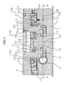
- Figs. 1 and 2 are a sectional elevation view and a sectional plan view, respectively, of an index table assembly 100 according to a first embodiment of the present invention in a state in which a rotary table 2 is unclamped.
- the sectional elevation view shown in Fig. 1 is taken along line B-B in Fig. 2
- the sectional plan view shown in Fig. 2 is taken along line A-A in Fig. 1 .
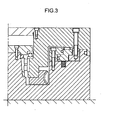
- Fig. 3 is a sectional view showing the main part of the index table assembly 100 in a state in which the rotary table 2 is clamped.
- the index table assembly 100 includes the rotary table 2, a frame 1 which supports the rotary table 2 such that the rotary table 2 can rotate, a worm wheel 4 fixed to the rotary table 2 with bolts (not shown), a worm 3 supported in the frame 1 by two tapered roller bearings 21 and a radial bearing 20 interposed between the worm 3 and the frame 1, and a drive motor 5 connected to the worm 3 with a coupling 6.
- the rotary table 2 has a workpiece-receiving surface 2a which is perpendicular to a rotational axis 15 and to which a process table, a jig, and the like (not shown) are attached and a clamping surface 2b.
- the clamping surface 2b is on the side opposite to the workpiece-receiving surface 2a, and is also perpendicular to the rotational axis 15.
- a cover 13 is attached to the rotary table 2 with bolts 25 to prevent foreign bodies such as cutting chips and cutting fluid from entering the inside of the index table assembly 100.
- the frame 1 has a base surface 1c which is fixed to a table surface of a machine tool (not shown) and a clamping surface 1b.
- the clamping surface 1b is on the side opposite to the base surface 1c, and is perpendicular to the rotational axis 15.
- the clamping surface 1b faces the clamping surface 2b of the rotary table 2.
- the frame 1 includes a shaft portion 1a centered on the rotational axis 15 at the central region of the frame 1, and a radial roller bearing 11 is provided on the shaft portion 1a.
- An inner race of the radial roller bearing 11 is fitted around the shaft portion 1a and an outer race of the radial roller bearing 11 is fitted to the rotary table 2, so that the rotary table 2 is rotatably supported by the radial roller bearing 11.
- the inner race of the radial roller bearing 11 is fixed to the shaft portion 1a with distance rings 26 and 27 and a bearing holder 14, which is detachably fixed to the shaft portion 1a with bolts 22 at an end of the shaft portion 1a.
- a clamping device 105 includes a fluid path 1d formed in the frame 1 and connected to a pressure fluid source (not shown), an annular cylinder 16 fixed to the frame 1 with bolts 23 and having a fluid path 16a communicating with the fluid path 1d, an annular piston 17 which is slidable along the rotational axis 15 while being guided by the outer peripheral surface of the cylinder 16, and a clamp ring 18 fixed to the rotary table 2 with bolts 24.
- a fluid pressure chamber 19 is provided between the outer peripheral surface of the cylinder 16 and the inner peripheral surface of the piston 17, and the fluid path 16a opens to the fluid pressure chamber 19 at one end thereof. Accordingly, the fluid pressure chamber 19 communicates with the fluid pressure source via the fluid paths 16a and 1d.
- a surface of the rotary table 2 on the side opposite to the workpiece-receiving surface 2a is separated from the frame 1 in the direction of the rotational axis 15, and an urging device 106 and a thrust needle bearing 9, which serves as a first bearing, are disposed between them.
- the urging device 106 includes a plurality of compression coil springs 28 inserted in spring holes formed in the frame 1 along a circle centered on the rotational axis 15 at a constant interval.
- the compression coil springs 28 are in contact with the piston 17 while applying an urging force to the piston 17, and thereby press the thrust needle bearing 9 against the rotary table 2 with the piston 17, which serves as an annular component, interposed therebetween.
- the rotary table 2 further has a surface on the side opposite to the side on which the thrust needle bearing 9 and the urging device 106 are provided, that is, on the same side as the workpiece-receiving surface 2a, and a thrust ball bearing 10, which serves as a second bearing, is placed between this surface and the bearing holder 14, that is, between this surface and the frame 1.
- the rotary table 2 When the rotary table 2 is unclamped, it is supported by the thrust needle bearing 9 and the thrust ball bearing 10 as described below and can easily rotate with low rotational resistance.
- the compression coil springs 28 are preferably designed by taking into account the load of onboard components such as a workpiece, a process table, and a jig and the load of the rotary table 2.
- the compression coil springs 28 generate an urging force sufficiently larger than the above-described loads placed thereon via the rotary table 2. Accordingly, when the pressure of the pressure fluid is reduced, the compression coil springs 28 press the piston 17, and the piston 17 presses the thrust needle bearing 9 against the rotary table 2.
- the piston 17, the thrust needle bearing 9, and the rotary table 2 move away from the base surface 1c, and the clamping surface 2b is separated from the clamping surface 1b.
- the rotary table 2 When the rotary table 2 moves away from the base surface 1c, it presses the thrust ball bearing 10 provided as the second bearing. More specifically, the rotary table 2 presses the thrust ball bearing 10 against the bearing holder 14, that is, against the frame 1, so that the rotary table 2 is positioned relative to the frame 1 in the direction of the rotational axis 15. In this state, the clamping surface 2b and the clamping surface 1b face each other with a predetermined gap provided therebetween.
- the compression coil springs 28 continuously generate an urging force sufficiently larger than the load of the onboard components such as a workpiece, a process table, and a jig and the load of the rotary table 2. Therefore, the rotary table 2 is prevented from being tilted due to these loads, particularly when the loads are placed unevenly. Accordingly, rotational resistance is not caused by contact between the clamping surface 2b and the clamping surface 1b.
- the rotary table 2 presses the bearing holder 14, that is, the frame 1 for positioning itself relative to the frame 1 in the direction of the rotational axis 15, the rotary table 2 presses the bearing holder 14 with the thrust ball bearing 10 interposed therebetween. Therefore, rotational resistance is not applied to the rotary table 2 by frictional force generated between the rotary table 2 and the frame 1.
- the rotary table 2 is prevented from coming into contact with the frame 1 at least when it rotates, that is, when it is unclamped in the present embodiment, so that rotational resistance of the rotary table 2 is not caused and the clamping surfaces 1b and 2b are prevented from being worn.
- the bearings that is, the thrust needle bearing 9 and the thrust ball bearing 10 are placed between the rotary table 2 and the frame 1, rotational resistance is not caused by engaging between the rotary table 2 and the frame 1 when the rotary table 2 is unclamped.
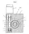
- Fig. 4 shows an index table assembly 110 according to a second embodiment of the present invention in a state in which a rotary table 2 is unclamped.
- the rotary table 2 includes a bearing support 60 and a workpiece receiver 61, and the bearing support 60 and the workpiece receiver 61 are fixed to each other with bolts 8.
- the workpiece receiver 61 has a workpiece-receiving surface 61a and a clamping surface 61b.
- a clamping device 115 includes an annular piston 17 and a frame 1 having a fluid path 1d connected to a pressure fluid source and a sliding surface along which the piston 17 slides on the inner periphery of the frame 1.
- a fluid pressure chamber 19 is formed between the inner peripheral surface of the frame 1 and the outer peripheral surface of the piston 17, and the fluid path 1d opens to the fluid pressure chamber 19 at one end thereof. Accordingly, the fluid pressure chamber 19 communicates with the fluid pressure source via the fluid path 1d.
- a surface of the rotary table 2 on the same side as the workpiece-receiving surface 61a is separated from the frame 1 in the direction of the rotational axis 15, and an urging device 116 and a thrust needle bearing 9, which serves as a first bearing, are disposed between them.
- the urging device 116 includes a plurality of compression coil springs 28 inserted in spring holes formed in a spring base 29, which is fixed to the frame 1 with bolts 57, along a circle centered on the rotational axis 15 at a constant interval.
- the compression coil springs 28 are in contact with the piston 17 while applying an urging force to the piston 17, and thereby press the thrust needle bearing 9 against the rotary table 2 with the piston 17, which serves as an annular component, interposed therebetween.
- the rotary table 2 further has a surface on the side opposite to the side on which the thrust needle bearing 9 and the urging device 116 are provided, that is, on the side opposite to the workpiece-receiving surface 61a, and a thrust ball bearing 10, which serves as a second bearing, is placed between this surface and the frame 1.
- Processes of clamping and unclamping the rotary table 2 by the clamping device 115 are performed similar to the first embodiment. More specifically, the piston 17 moves toward the workpiece-receiving surface 61a along the rotational axis 15 against the urging force applied by the compression coil springs 28. Accordingly, the rotary table 2, which engages with the piston 17, moves away from a base surface 1c until the clamping surface 61b of the rotary table 2 and a clamping surface 29a of the spring base 29 come into contact with each other. Thus, the rotary table 2 is fixed to the frame 1 by a frictional force and is clamped such that it cannot rotate.
- the rotary table 2 When the rotary table 2 is unclamped, it is released such that it can rotate, and is supported by the thrust needle bearing 9 and the thrust ball bearing 10 such that it can easily rotate with low rotational resistance.
- the rotary table 2 is positioned in the direction of the rotational axis 15 by the thrust ball bearing 10 such that the clamping surfaces 61b and 29a face each other with a predetermined gap provided therebetween.
- the rotary table 2 When the rotary table 2 moves toward the base surface 1c, it presses the thrust ball bearing 10, which is provided as the second bearing. More specifically, the rotary table 2 presses the thrust ball bearing 10 against the frame 1, so that the rotary table 2 is positioned relative to the frame 1 in the direction of the rotational axis 15. In this state, the clamping surface 61b and the clamping surface 29a face each other with a predetermined gap provided therebetween.
- the rotary table 2 is prevented from coming into contact with the frame 1 at least when it rotates, that is, when it is unclamped in the present embodiment, so that rotational resistance of the rotary table 2 is not caused and the clamping surfaces 29a and 61b are prevented from being worn.
- the bearings that is, the thrust needle bearing 9 and the thrust ball bearing 10 are placed between the rotary table 2 and the frame 1, rotational resistance is not caused by engaging between the rotary table 2 and the frame 1.
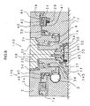
- Fig. 5 shows an index table assembly 120 according to a third embodiment of the present invention in a state in which a rotary table 2 is unclamped.
- the urging device 106 includes a plurality of springs.
- an urging device 126 of the index table assembly 120 includes a hydraulic actuator.
- the index table assembly 120 includes a tapered roller bearing 32 as a second bearing. The tapered roller bearing 32 serves the functions of both a radial bearing and a thrust bearing.
- a frame 1 includes a shaft portion 1a centered on a rotational axis 15 at the central region of the frame 1, and the tapered roller bearing 32 is provided on the shaft portion 1a.
- An inner race of the tapered roller bearing 32 is fitted around the shaft portion 1a and an outer race of the tapered roller bearing 32 is fitted to the rotary table 2, so that the rotary table 2 is rotatably supported by the tapered roller bearing 32.
- the inner race of the tapered roller bearing 32 is fixed to the shaft portion 1a with a distance ring 34 and a nut 33 which is screwed on a male thread formed in the shaft portion 1a at an end thereof.
- a clamping device 125 is identical to the clamping device 105 included in the index table assembly 100 according to the first embodiment is provided. Similar to the clamping device 105, the rotary table 2 is clamped by bringing a clamping surface 2b of the rotary table 2 and a clamping surface 1b of the frame 1 into contact with each other.
- a surface of the rotary table 2 on the side opposite to a workpiece-receiving surface 2a is separated from the frame 1 in the direction of a rotational axis 15, and the urging device 126 and a thrust needle bearing 9, which serves as a first bearing, are disposed between them.
- the urging device 126 includes a piston 17 and a cylinder 16 included in the clamping device 125, the frame 1, and a fluid path 1e formed in the frame 1 and connected to a pressure fluid source (not shown).
- a fluid pressure chamber 31 for urging is provided between the outer peripheral surface of the cylinder 16 and the inner peripheral surface of the frame 1, and the fluid path 1e opens to the fluid pressure chamber 31 at one end thereof. Accordingly, the fluid pressure chamber 31 communicates with the fluid pressure source via the fluid path 1e.
- a switching valve (not shown) changes the flow path to which pressure fluid from the pressure fluid source is supplied from a fluid path 1d to the fluid path 1e. Accordingly, the pressure of the pressure fluid in a fluid pressure chamber 30 is reduced and the rotary table 2 is unclamped.
- the pressure fluid flows into the fluid pressure chamber 31 and moves the piston 17 toward the workpiece-receiving surface 2a.
- the piston 17 presses the thrust needle bearing 9 against the rotary table 2
- the rotary table 2 presses the outer race of the tapered roller bearing 32.
- the outer race of the tapered roller bearing 32 presses rolling elements which are restrained from moving along the rotational axis 15 by the inner race. Accordingly, the rotary table 2 is positioned in the direction of the rotational axis 15, and the clamping surfaces 2b and 1b face each other with a predetermined gap provided therebetween.
- the switching valve when the rotary table 2 is unclamped, changes the flow path to which the pressure fluid from the pressure fluid source is supplied from the fluid path 1d to the fluid path 1e.
- supply of the pressure fluid may also be stopped when the rotary table 2 is unclamped. In such a case, the pressure fluid is supplied to the fluid path 1e when the rotary table 2 rotates.
- the rotary table 2 is prevented from coming into contact with the frame 1 at least when it rotates, so that rotational resistance of the rotary table 2 is not caused and the clamping surfaces 1b and 2b are prevented from being worn.
- the bearings that is, the thrust needle bearing 9 and the tapered roller bearing 32 are placed between the rotary table 2 and the frame 1, rotational resistance is not caused by engaging between the rotary table 2 and the frame 1.
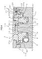
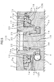
- Fig. 6 shows an index table assembly 130 according to a fourth embodiment of the present invention in a state in which a rotary table 2 is unclamped.
- a frame 1 includes a shaft portion 1a centered on a rotational axis 15 at the central region of the frame 1, and a radial roller bearing 11 is provided on the shaft portion 1a.
- An inner race of the radial roller bearing 11 is fitted around the shaft portion 1a and an outer race of the radial roller bearing 11 is fitted to the rotary table 2, so that the rotary table 2 is rotatably supported by the radial roller bearing 11.
- the inner race of the radial roller bearing 11 is fixed to the shaft portion 1a with distance rings 26 and 27 and a bearing holder 14 which is detachably fixed to the shaft portion 1a with bolts 22 at an end of the shaft portion 1a.
- a clamping device 135 includes a fluid path 1d formed in the frame 1 and connected to a pressure fluid source (not shown); a plurality of cylinder holes 1h formed in the frame 1 along a circle centered on the rotational axis 15 at a constant interval; pistons 35 inserted in the cylinder holes 1h and having flanges at an end thereof; piston holders 36 fixed to the frame 1 with bolts 43 and inserted into the cylinder holes 1h; a piston groove 37 with a T-shaped cross section formed in the rotary table 2 along a circle centered on the rotational axis 15 over the entire circumference thereof such that the piston groove 37 opens in a clamping surface 2b, the piston groove 37 accommodating the flanges of the pistons 35; and compression coil springs 45 inserted in spring holes formed in the pistons 35 at the end opposite to the flanges.
- Fluid pressure chambers 39 are formed between the cylinder holes 1h and the pistons 35, and the fluid path 1d opens to the fluid pressure chambers 39 at one end thereof.
- the compression coil springs 45 are in contact with the frame 1 at one end thereof and urge the pistons 35 toward a workpiece-receiving surface 2a.
- a surface of the rotary table 2 on the side opposite to the workpiece-receiving surface 2a is separated from the frame 1 in the direction of the rotational axis 15, and an urging device 136, a pressing ring 41, and a thrust ball bearing 40, which serves as a first bearing, are disposed between them.
- the urging device 136 includes a plurality of compression coil springs 28 inserted in spring holes formed in the frame 1 along a circle centered on the rotational axis 15 at a constant interval.
- the compression coil springs 28 are in contact with the pressing ring 41 while applying an urging force to the pressing ring 41, and thereby press the thrust ball bearing 40 against the rotary table 2 with the pressing ring 41 interposed therebetween.
- a guide ring 42 is fixed to the frame 1 with bolts 44, and the pressing ring 41 is guided by the guide ring 42.
- the rotary table 2 When the rotary table 2 is unclamped, the pressure of the pressure fluid is reduced and the pistons 35 are pressed against the rotary table 2 by the urging force applied by the compression coil springs 45, so that the clamping surfaces 1b and 2b are released from each other. Accordingly, the rotary table 2 is unclamped such that it can rotate.
- the rotary table 2 when the rotary table 2 unclamped, it is supported by two thrust bearings, that is, the thrust ball bearing 40 and a thrust ball bearing 10 and can easily rotate with low rotational resistance.
- the compression coil springs 28 press the pressing ring 41, and the pressing ring 41 presses the thrust ball bearing 40 against the rotary table 2.
- the pressing ring 41, the thrust ball bearing 40, and the rotary table 2 move away from the base surface 1c, and the clamping surface 2b is separated from the clamping surface 1b.
- the rotary table 2 presses the thrust ball bearing 10, which is provided as a second bearing, so that the rotary table 2 is positioned relative to the frame 1 in the direction of the rotational axis 15.
- the clamping surface 2b and the clamping surface 1b face each other with a predetermined gap provided therebetween.
- rotational resistance of the rotary table 2 is not caused and the rotary table 2 and the frame 1 are prevented from being worn by coming into contact with each other at least when the rotary table 2 rotates, that is, when it is unclamped in the present embodiment.
- a plurality of spring holes for receiving the compression coil springs 28 may also be formed in the rotary table 2 along a circle centered on the rotational axis 15 at a constant interval.
- the compression coil springs 28 press the thrust ball bearing 40 against the frame 1 with the pressing ring 41 interposed therebetween.
- the clamping surfaces 1b and 2b are separated from each other when the rotary table 2 is unclamped.
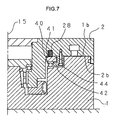
- Fig. 8 shows an index table assembly 140 according to a fifth embodiment of the present invention in a state in which a rotary table 2 is unclamped.
- a surface of the rotary table 2 on the side opposite to a workpiece-receiving surface 2a is separated from a frame 1 in the direction of a rotational axis 15, and an urging device identical to the urging device 136 included in the index table assembly 130 according to the fourth embodiment, a pressing ring 41, and a thrust ball bearing 40 are disposed between them.
- Two clamping devices 145 and 146 are provided, the clamping device 145 being used for bringing the rotary table 2 into contact with the frame 1 by moving the rotary table 2 along the rotational axis 15 and the clamping device 146 being used for bringing a component fixed to the frame 1 into contact with the rotary table 2 by deforming the component.
- the frame 1 has a shaft portion 1a centered on the rotational axis 15 at the central region of the frame 1, and a tapered roller bearing 32 is provided on the shaft portion 1a.
- An inner race of the tapered roller bearing 32 is fitted around the shaft portion 1a and an outer race of the tapered roller bearing 32 is fitted to the rotary table 2, so that the rotary table 2 is rotatably supported by the tapered roller bearing 32.
- the inner race of the tapered roller bearing 32 is fixed to the shaft portion 1a with a distance ring 34 and a nut 33 which is screwed on a male thread formed in the shaft portion 1a at an end thereof.
- the frame 1 has a through hole centered on the rotational axis 15, and a center shaft 48 fixed to the rotary table 2 with bolts 54 is inserted into the through hole.
- the through hole is provided with a cylinder in which a piston 50 is inserted.
- a fluid pressure chamber 51 is formed in the cylinder, and a fluid path 1f formed in the frame 1 and connected to a pressure fluid source opens to the fluid pressure chamber 51.
- a piston holder 49 is fixed on an end surface of the center shaft 48 with bolts 55 such that the piston holder 49 extends through a through hole formed in the piston 50 and is engaged with the piston 50.
- a spring holder 52 having a plurality of spring holes arranged along a circle centered on the rotational axis 15 is fixed to the frame 1 with bolts 56.
- the spring holes formed in the spring holder 52 accommodate compression coil springs 45 which are in contact with the piston 50 at one end thereof, and the compression coil springs 45 urge the piston 50 toward the workpiece-receiving surface 2a.
- the clamping device 145 includes the cylinder formed in the through hole of the frame 1, the piston 50, the compression coil springs 45, the spring holder 52, the piston holder 49, and the fluid path 1f.
- the rotary table 2 moves along the rotational axis 15 and comes into contact with the frame 1.
- a clamp ring 46 is fixed to the frame 1 with bolts 53.
- the clamp ring 46 extends along the rotational axis 15, and the inner peripheral surface of the clamp ring 46 is fitted around a shaft portion 2c of the rotary table 2.
- the clamp ring 46 has a groove with a certain width along the rotational axis 15 in the outer peripheral surface thereof, the groove extending over the entire circumference of the clamp ring 46. Accordingly, a fluid pressure chamber 47 is formed between the clamp ring 46 and the frame 1 such that a thin portion of the clamp ring 46 is provided between the fluid pressure chamber 47 and the shaft portion 2c.
- the frame 1 has a fluid path 1g connected to the pressure fluid source, and the fluid path 1g opens to the fluid pressure chamber 47 at one end thereof.
- the clamping device 146 includes the clamp ring 46 and the fluid path 1g.
- the pressure fluid is supplied to the fluid pressure chamber 47, the thin portion of the clamp ring 46 fixed to the frame 1 is deformed and comes into contact with the rotary table 2.
- the pressure fluid is supplied to the fluid path 1f, and the piston 50 moves toward a base surface 1c of the frame 1 against the urging force applied by the compression coil springs 28 and 45 and press the piston holder 49, which is engaged with the piston 50. Accordingly, the piston holder 49 and the rotary table 2 moves together until a clamping surface 1b of the frame 1 and a clamping surface 2b of the rotary table 2 come into contact with each other. Thus, the rotary table 2 is clamped. Next, the pressure fluid is supplied to the fluid path 1g so that it flows into the fluid pressure chamber 47.
- the thin portion of the clamp ring 46 is deformed such that it swells inward and comes into contact with the shaft portion 2c of the rotary table 2.
- the clamp ring 46 which is fixed to the frame 1, comes into contact with the rotary table 2 and the rotary table 2 is strongly clamped.
- the rotary table 2 When the rotary table 2 is unclamped, the pressure of the pressure fluid is reduced, so that the clamping surfaces 1b and 2b are released from each other and the thin portion of the clamp ring 46 and the shaft portion 2c of the rotary table 2 are also released from each other. Accordingly, the rotary table 2 is unclamped such that it can rotate.
- the compression coil springs 28 press the pressing ring 41, and the pressing ring 41 presses the thrust ball bearing 40 against the rotary table 2. Accordingly, the rotary table 2 presses the outer race of the tapered roller bearing 32.
- the outer race of the tapered roller bearing 32 presses rolling elements which are restrained from moving along the rotational axis 15 by the inner race. Accordingly, the rotary table 2 is positioned in the direction of the rotational axis 15, and the clamping surfaces 2b and 1b face each other with a predetermined gap provided therebetween.
- a plurality of spring holes for receiving the compression coil springs 28 may also be formed in the rotary table 2 along a circle centered on the rotational axis 15 at a constant interval.
- the compression coil springs 28 presses the thrust ball bearing 40 against the frame 1 with the pressing ring 41 interposed therebetween.
- the clamping surfaces 1b and 2b are separated from each other when the rotary table 2 is unclamped.
Landscapes
- Engineering & Computer Science (AREA)
- Mechanical Engineering (AREA)
- Machine Tool Units (AREA)
- Machine Tool Positioning Apparatuses (AREA)
- Automobile Manufacture Line, Endless Track Vehicle, Trailer (AREA)
Claims (5)
- Drehtischanordnung (100, 110, 120, 130, 140) mit einer Klemmvorrichtung (105, 115, 125, 235, 135), um einen Drehtisch (2) in Kontakt mit einem Rahmen (1) zu bringen, indem der Drehtisch (2) entlang einer Rotationsachse (14) des Drehtischs (2) bewegt wird, aufweisend:ein erstes Lager (9, 40), das zwischen dem Drehtisch (2) und dem Rahmen (1) angeordnet ist, welcher vom Drehtisch (2) in Richtung der Rotationsachse (15) separiert ist, undeine Stelleinrichtung (106, 116, 126, 136), welche zwischen dem ersten Lager (9, 40) und entweder dem Drehtisch (2) oder dem Rahmen (1) angeordnet ist und welche das erste Lager (9, 40) entsprechend entweder gegen den Drehtisch (2) oder das Lager (1) drückt, wenigstens wenn sich der Drehtisch (2) dreht, dadurch gekennzeichnet, dass Folgendes vorgesehen ist:ein zweites Lager (10, 32), welches zwischen einer Fläche des Drehtischs (2) und dem Rahmen (1), welcher der Fläche zugewandt ist, an einer Seite angeordnet ist, die der Seite gegenüberliegt, an welcher das erste Lager (9, 40) und die Stelleinrichtung (106, 116, 126, 136) vorgesehen sind, wobeidie Stelleinrichtung (106, 116, 126, 136) den Drehtisch (2) gegen das zweite Lager (10, 32) drückt, wenigstens wenn sich der Drehtisch (2) dreht.
- Drehtischanordnung (100, 110, 130, 140) nach Anspruch 1, bei welcher die Stelleinrichtung (106, 116, 136) mehrere Federn (28) aufweist, welche entlang eines Kreises angeordnet ist, welcher in der Rotationsachse (14) des Drehtischs zentriert ist, und die Klemmvorrichtung (105, 115, 135, 145) den Drehtisch (2) gegen die Stellkraft in Kontakt mit dem Rahmen (1) bringt.
- Drehtischanordnung (120) nach Anspruch 1, bei welcher die Stelleinrichtung (126) ein hydraulisches Stellelement aufweist, welches nicht aktiviert ist, wenn der Drehtisch (2) festgeklemmt ist.
- Drehtischanordnung (100, 110, 120, 130, 140) nach einem der Ansprüche 1 bis 3, bei welcher die Stelleinrichtung (106, 116, 126, 136) das erste Lager (9, 40) über ein ringförmiges Bauteil (17, 41) entsprechend gegen das Gegenstück zum Drehtisch (2) bzw. zum Rahmen (1) drückt.
- Drehtischanordnung (100, 120) gemäß Anspruch 4, bei welcher die Klemmvorrichtung (105, 125) das ringförmige Bauteil (17) umfasst und den Drehtisch (2) mit dem ringförmigen Bauteil (17) gegen den Rahmen (1) drückt, und die Stelleinrichtung (106, 126) zwischen dem ersten Lager (9) und dem Rahmen (1) angeordnet ist und das erste Lager (9) mit dem ringförmigen Bauteil (17) gegen den Drehtisch (2) drückt.
Applications Claiming Priority (2)
| Application Number | Priority Date | Filing Date | Title |
|---|---|---|---|
| JP2003376465 | 2003-11-06 | ||
| JP2003376465A JP4727917B2 (ja) | 2003-11-06 | 2003-11-06 | インデックステーブル |
Publications (3)
| Publication Number | Publication Date |
|---|---|
| EP1529595A2 EP1529595A2 (de) | 2005-05-11 |
| EP1529595A3 EP1529595A3 (de) | 2006-02-15 |
| EP1529595B1 true EP1529595B1 (de) | 2008-09-17 |
Family
ID=34431295
Family Applications (1)
| Application Number | Title | Priority Date | Filing Date |
|---|---|---|---|
| EP04025663A Revoked EP1529595B1 (de) | 2003-11-06 | 2004-10-28 | Drehtisch mit Tischklemmvorrichtung |
Country Status (5)
| Country | Link |
|---|---|
| US (2) | US7418889B2 (de) |
| EP (1) | EP1529595B1 (de) |
| JP (1) | JP4727917B2 (de) |
| CN (1) | CN100429041C (de) |
| DE (1) | DE602004016608D1 (de) |
Families Citing this family (30)
| Publication number | Priority date | Publication date | Assignee | Title |
|---|---|---|---|---|
| JP4320241B2 (ja) * | 2003-11-07 | 2009-08-26 | 津田駒工業株式会社 | インデックステーブル |
| JP4883815B2 (ja) * | 2007-01-15 | 2012-02-22 | 津田駒工業株式会社 | 工作機械用の割出装置 |
| JP4993723B2 (ja) * | 2007-07-12 | 2012-08-08 | 津田駒工業株式会社 | 割出装置 |
| JP5152896B2 (ja) * | 2007-10-10 | 2013-02-27 | 津田駒工業株式会社 | 工作機械における回転割出し装置 |
| US8028605B2 (en) * | 2008-03-21 | 2011-10-04 | Mori Seiki Co., Ltd. | Circular dividing table for machine tool |
| JP2009248230A (ja) * | 2008-04-04 | 2009-10-29 | Toshiba Mach Co Ltd | 割出しテーブル装置 |
| DE102008053163A1 (de) | 2008-10-24 | 2010-04-29 | Thyssenkrupp Drauz Nothelfer Gmbh | Vorrichtung zur Werkstückpositionierung |
| DE102008021653B3 (de) * | 2008-04-30 | 2010-01-07 | Thyssenkrupp Drauz Nothelfer Gmbh | Vorrichtung zur Werkstückpositionierung |
| JP5286047B2 (ja) * | 2008-11-19 | 2013-09-11 | 津田駒工業株式会社 | 工作機械用の主軸駆動装置におけるクランプ装置 |
| JP5277057B2 (ja) * | 2009-04-14 | 2013-08-28 | 津田駒工業株式会社 | 工作機械用の主軸駆動装置における回転抵抗付与装置 |
| JP5347782B2 (ja) * | 2009-07-09 | 2013-11-20 | 村田機械株式会社 | カップリング装置 |
| WO2011033164A1 (en) * | 2009-09-17 | 2011-03-24 | Kinshofer Gmbh | Rotation device |
| CN102712068B (zh) | 2009-10-16 | 2015-01-07 | 韦斯有限公司 | 圆分度工作台 |
| US20120180584A1 (en) * | 2011-01-13 | 2012-07-19 | Weiss Gmbh Sondermaschinentechnik | Pivotal drive |
| CN102133711A (zh) * | 2011-01-20 | 2011-07-27 | 长沙哈量凯帅精密机械有限公司 | 一种控制回转工作台角位移的装置 |
| CN102990507B (zh) * | 2011-09-09 | 2015-09-16 | 新乡日升数控轴承装备股份有限公司 | 立式磨床磨头上的分度支撑机构 |
| KR101407527B1 (ko) * | 2012-05-18 | 2014-06-13 | 한국기계연구원 | 테이블 업다운 회전오차 방지 장치 |
| JP6505472B2 (ja) * | 2015-03-03 | 2019-04-24 | 津田駒工業株式会社 | 回転テーブル装置 |
| JP6207568B2 (ja) * | 2015-10-20 | 2017-10-04 | 株式会社オーエム製作所 | 偏心量調整機構を備えた旋盤 |
| JP6285402B2 (ja) * | 2015-11-12 | 2018-02-28 | ファナック株式会社 | 回転テーブル装置のクランプ機構 |
| JP6686554B2 (ja) * | 2016-03-09 | 2020-04-22 | 株式会社ジェイテクト | 回転テーブル装置、及び当該装置を備えた工作機械 |
| US20170326702A1 (en) * | 2016-05-12 | 2017-11-16 | Tsudakoma Kogyo Kabushiki Kaisha | Rotary table device for machine tool |
| WO2017195956A1 (ko) * | 2016-05-12 | 2017-11-16 | 주식회사 에코텍 | 공작물 가공용 회전 테이블 |
| KR20180028095A (ko) * | 2016-09-07 | 2018-03-16 | 한국산업기술대학교산학협력단 | 홀 가공 장치 |
| CN107283221A (zh) * | 2017-06-20 | 2017-10-24 | 衢州职业技术学院 | 一种加工用分度定位装置 |
| CN108247430B (zh) * | 2018-01-31 | 2019-07-12 | 重庆九源机械有限公司 | 一种双工作台双主轴加工中心 |
| CN108453519A (zh) * | 2018-04-03 | 2018-08-28 | 环球工业机械(东莞)有限公司 | 一种静压回转工作台精密定心防倾斜装置 |
| KR102675800B1 (ko) * | 2019-04-09 | 2024-06-17 | 주식회사 디엔솔루션즈 | 공작기계의 테이블 |
| JP7569266B2 (ja) * | 2021-05-19 | 2024-10-17 | 津田駒工業株式会社 | 回転テーブル装置 |
| JP7680739B2 (ja) * | 2021-07-19 | 2025-05-21 | テクノダイナミックス株式会社 | バレルカム装置 |
Family Cites Families (15)
| Publication number | Priority date | Publication date | Assignee | Title |
|---|---|---|---|---|
| JPS5384279A (en) * | 1976-12-29 | 1978-07-25 | Fanuc Ltd | Indexing table |
| US4159658A (en) * | 1977-04-04 | 1979-07-03 | Bridgeport Machines Division Of Textron Inc. | Rotary index tables |
| DE3134969C2 (de) * | 1981-09-04 | 1984-05-17 | Sauter Feinmechanik GmbH, 7430 Metzingen | Werkzeugrevolver |
| CN85106747A (zh) * | 1985-09-05 | 1987-03-25 | 卡尼特雷克公司 | 机床的旋转往复送件机构 |
| CN2054392U (zh) * | 1989-01-31 | 1990-03-14 | 山东菏泽油泵油嘴厂 | 新型机床回转换位装置 |
| JPH0750133Y2 (ja) * | 1989-08-01 | 1995-11-15 | 株式会社森精機製作所 | 工作機械のインデックステーブルの割出し装置 |
| JPH0329249A (ja) * | 1990-06-12 | 1991-02-07 | Seiko Instr Inc | 集束イオンビーム装置 |
| JP3141635B2 (ja) | 1993-08-05 | 2001-03-05 | 富士電機株式会社 | マイクロ真空管 |
| JPH1029125A (ja) * | 1996-07-15 | 1998-02-03 | Toyoda Mach Works Ltd | 回転割出し装置 |
| US5735514A (en) * | 1996-09-03 | 1998-04-07 | Chick Machine Tool, Inc. | Indexing apparatus |
| NL1004362C2 (nl) | 1996-10-25 | 1998-04-28 | Stichting Vakraad Voor De Meub | Inrichting voor het voor bewerking beweegbaar opstellen van een werkstuk. |
| JPH1177489A (ja) | 1997-09-01 | 1999-03-23 | Mori Seiki Co Ltd | 工作機械の割り出し機構 |
| DE60112128T2 (de) | 2001-04-30 | 2006-04-20 | Duplomatic Automazione S.P.A., Busto Arsizio | Multifunktionaler positionsmechanismus als träger für werkzeughalter |
| JP2003194156A (ja) * | 2001-12-27 | 2003-07-09 | Mori Seiki Co Ltd | 工作機械の旋回割り出し装置 |
| JP3720298B2 (ja) * | 2001-12-28 | 2005-11-24 | 株式会社森精機製作所 | 工作機械の回転割り出し装置 |
-
2003
- 2003-11-06 JP JP2003376465A patent/JP4727917B2/ja not_active Expired - Fee Related
-
2004
- 2004-08-09 US US10/913,547 patent/US7418889B2/en not_active Expired - Lifetime
- 2004-10-28 EP EP04025663A patent/EP1529595B1/de not_active Revoked
- 2004-10-28 DE DE602004016608T patent/DE602004016608D1/de not_active Expired - Lifetime
- 2004-11-05 CN CNB2004100922674A patent/CN100429041C/zh not_active Expired - Fee Related
-
2008
- 2008-02-13 US US12/068,933 patent/US7942080B2/en not_active Expired - Fee Related
Also Published As
| Publication number | Publication date |
|---|---|
| CN100429041C (zh) | 2008-10-29 |
| US20080148901A1 (en) | 2008-06-26 |
| EP1529595A2 (de) | 2005-05-11 |
| DE602004016608D1 (de) | 2008-10-30 |
| JP2005138216A (ja) | 2005-06-02 |
| US20050151048A1 (en) | 2005-07-14 |
| US7418889B2 (en) | 2008-09-02 |
| JP4727917B2 (ja) | 2011-07-20 |
| CN1628932A (zh) | 2005-06-22 |
| EP1529595A3 (de) | 2006-02-15 |
| US7942080B2 (en) | 2011-05-17 |
Similar Documents
| Publication | Publication Date | Title |
|---|---|---|
| EP1529595B1 (de) | Drehtisch mit Tischklemmvorrichtung | |
| EP2168719B1 (de) | Klemmvorrichtung für rundtaktvorrichtung einer werkzeugmaschine | |
| US8028605B2 (en) | Circular dividing table for machine tool | |
| US8505895B2 (en) | Clamping device in main shaft driving device for machine tool | |
| US7931131B2 (en) | Rotational resistance applying device in main shaft driving device for machine tool | |
| US5177905A (en) | Tool attaching/detaching device | |
| KR20090032956A (ko) | 공작기계용의 회전분할장치를 위한 클램프장치 | |
| EP1529596B1 (de) | Drehtisch mit zwei Lagern | |
| CN107695877B (zh) | 尾座 | |
| KR20100125401A (ko) | 공작기계에 있어서의 주축 구동 장치의 회전 저항 장치 | |
| JP2006095668A (ja) | 回転テーブル装置 | |
| JP2009248230A (ja) | 割出しテーブル装置 | |
| JPH0567829U (ja) | 回動軸部のクランプ装置 | |
| JP4470399B2 (ja) | 油圧クランプ装置 | |
| US12409524B2 (en) | Barrel cam device | |
| JP4358560B2 (ja) | 刃物台の工具旋回装置 | |
| JP5412944B2 (ja) | 回転体のクランプ装置 | |
| JP2003340705A (ja) | 研削装置 | |
| JPH1190782A (ja) | 回転割出装置 | |
| CN118513615A (zh) | 内齿轮磨齿工装及其使用方法 | |
| JPS62228304A (ja) | 心押装置 |
Legal Events
| Date | Code | Title | Description |
|---|---|---|---|
| PUAI | Public reference made under article 153(3) epc to a published international application that has entered the european phase |
Free format text: ORIGINAL CODE: 0009012 |
|
| AK | Designated contracting states |
Kind code of ref document: A2 Designated state(s): AT BE BG CH CY CZ DE DK EE ES FI FR GB GR HU IE IT LI LU MC NL PL PT RO SE SI SK TR |
|
| AX | Request for extension of the european patent |
Extension state: AL HR LT LV MK |
|
| PUAL | Search report despatched |
Free format text: ORIGINAL CODE: 0009013 |
|
| AK | Designated contracting states |
Kind code of ref document: A3 Designated state(s): AT BE BG CH CY CZ DE DK EE ES FI FR GB GR HU IE IT LI LU MC NL PL PT RO SE SI SK TR |
|
| AX | Request for extension of the european patent |
Extension state: AL HR LT LV MK |
|
| RIC1 | Information provided on ipc code assigned before grant |
Ipc: B23Q 1/28 20060101AFI20051223BHEP Ipc: B23Q 16/10 20060101ALI20051223BHEP |
|
| 17P | Request for examination filed |
Effective date: 20060331 |
|
| 17Q | First examination report despatched |
Effective date: 20060719 |
|
| AKX | Designation fees paid |
Designated state(s): CH DE FR IT LI |
|
| GRAP | Despatch of communication of intention to grant a patent |
Free format text: ORIGINAL CODE: EPIDOSNIGR1 |
|
| GRAS | Grant fee paid |
Free format text: ORIGINAL CODE: EPIDOSNIGR3 |
|
| GRAA | (expected) grant |
Free format text: ORIGINAL CODE: 0009210 |
|
| AK | Designated contracting states |
Kind code of ref document: B1 Designated state(s): CH DE FR IT LI |
|
| REG | Reference to a national code |
Ref country code: CH Ref legal event code: NV Representative=s name: E. BLUM & CO. AG PATENT- UND MARKENANWAELTE VSP Ref country code: CH Ref legal event code: EP |
|
| REF | Corresponds to: |
Ref document number: 602004016608 Country of ref document: DE Date of ref document: 20081030 Kind code of ref document: P |
|
| PLBI | Opposition filed |
Free format text: ORIGINAL CODE: 0009260 |
|
| PLAX | Notice of opposition and request to file observation + time limit sent |
Free format text: ORIGINAL CODE: EPIDOSNOBS2 |
|
| 26 | Opposition filed |
Opponent name: FIBRO GMBH Effective date: 20090617 |
|
| PGFP | Annual fee paid to national office [announced via postgrant information from national office to epo] |
Ref country code: FR Payment date: 20101020 Year of fee payment: 7 |
|
| PLAY | Examination report in opposition despatched + time limit |
Free format text: ORIGINAL CODE: EPIDOSNORE2 |
|
| PGFP | Annual fee paid to national office [announced via postgrant information from national office to epo] |
Ref country code: CH Payment date: 20101012 Year of fee payment: 7 Ref country code: DE Payment date: 20101020 Year of fee payment: 7 |
|
| PGFP | Annual fee paid to national office [announced via postgrant information from national office to epo] |
Ref country code: IT Payment date: 20101022 Year of fee payment: 7 |
|
| RDAF | Communication despatched that patent is revoked |
Free format text: ORIGINAL CODE: EPIDOSNREV1 |
|
| REG | Reference to a national code |
Ref country code: DE Ref legal event code: R103 Ref document number: 602004016608 Country of ref document: DE Ref country code: DE Ref legal event code: R064 Ref document number: 602004016608 Country of ref document: DE |
|
| RDAG | Patent revoked |
Free format text: ORIGINAL CODE: 0009271 |
|
| STAA | Information on the status of an ep patent application or granted ep patent |
Free format text: STATUS: PATENT REVOKED |
|
| REG | Reference to a national code |
Ref country code: CH Ref legal event code: PL |
|
| 27W | Patent revoked |
Effective date: 20110826 |
|
| PG25 | Lapsed in a contracting state [announced via postgrant information from national office to epo] |
Ref country code: CH Free format text: LAPSE BECAUSE OF THE APPLICANT RENOUNCES Effective date: 20080917 Ref country code: LI Free format text: LAPSE BECAUSE OF THE APPLICANT RENOUNCES Effective date: 20080917 |
|
| REG | Reference to a national code |
Ref country code: DE Ref legal event code: R107 Ref document number: 602004016608 Country of ref document: DE Effective date: 20120301 |