EP1529470B2 - Module de chauffage avec surface chauffante et chaudière instantanée et procédé pour sa fabrication - Google Patents
Module de chauffage avec surface chauffante et chaudière instantanée et procédé pour sa fabrication Download PDFInfo
- Publication number
- EP1529470B2 EP1529470B2 EP03025226A EP03025226A EP1529470B2 EP 1529470 B2 EP1529470 B2 EP 1529470B2 EP 03025226 A EP03025226 A EP 03025226A EP 03025226 A EP03025226 A EP 03025226A EP 1529470 B2 EP1529470 B2 EP 1529470B2
- Authority
- EP
- European Patent Office
- Prior art keywords
- heating
- heating unit
- channel
- extruded profile
- conduit
- Prior art date
- Legal status (The legal status is an assumption and is not a legal conclusion. Google has not performed a legal analysis and makes no representation as to the accuracy of the status listed.)
- Expired - Lifetime
Links
Images


Classifications
-
- A—HUMAN NECESSITIES
- A47—FURNITURE; DOMESTIC ARTICLES OR APPLIANCES; COFFEE MILLS; SPICE MILLS; SUCTION CLEANERS IN GENERAL
- A47J—KITCHEN EQUIPMENT; COFFEE MILLS; SPICE MILLS; APPARATUS FOR MAKING BEVERAGES
- A47J31/00—Apparatus for making beverages
- A47J31/44—Parts or details or accessories of beverage-making apparatus
- A47J31/54—Water boiling vessels in beverage making machines
- A47J31/542—Continuous-flow heaters
-
- Y—GENERAL TAGGING OF NEW TECHNOLOGICAL DEVELOPMENTS; GENERAL TAGGING OF CROSS-SECTIONAL TECHNOLOGIES SPANNING OVER SEVERAL SECTIONS OF THE IPC; TECHNICAL SUBJECTS COVERED BY FORMER USPC CROSS-REFERENCE ART COLLECTIONS [XRACs] AND DIGESTS
- Y10—TECHNICAL SUBJECTS COVERED BY FORMER USPC
- Y10T—TECHNICAL SUBJECTS COVERED BY FORMER US CLASSIFICATION
- Y10T29/00—Metal working
- Y10T29/49—Method of mechanical manufacture
- Y10T29/49826—Assembling or joining
Definitions
- the invention relates to a heating module according to the preamble of claim 1.
- Heating modules are used as a heat source in household or laboratory appliances, such as coffee machines.
- a heating coil is used to heat with the heating surface a cover plate with a keep-warm function.
- a disadvantage of the device DE 25 37 769 A1 is, however, that an additional power control of the heating coil by a protective thermostat is necessary to prevent overheating of the heating coil. This increases the production costs of the electrical appliance in which the heating module of DE 25 37 769 A1 is used, at the same time increases its error rate.
- a PTC element Pulsitive Temperature Coefficient
- the PTC element Due to its material properties, the PTC element only heats up to a predetermined limit temperature, above the limit temperature the PTC element switches off the heat production automatically.
- This advantage of the PTC element is, however, outweighed by the fact that its attachment in the heating module is structurally complex and can only be realized with a high manufacturing outlay. So are the heating modules of the DE 28 04 818 C2 and the DE 29 48 591 C2 provided additional devices in the form of Klammem and springs through which the PTC heating element is pressed against a radiator to achieve a good heat transfer.
- EP 0 573 691 B1 another approach: a PTC element is pressed in an extruded profile, which has a heatable base plate as a heating surface.
- a disadvantage of the heating module of EP 0 573 691 B1 is, however, that due to its limited functionality, the area of use in home and laboratory equipment compared to the devices of the DE 28 04 818 C2 and the DE 29 48 591 C2 remains limited.
- a liquid heating tube in which a PTC heating element is clamped in a cavity of a radiator.
- longitudinal ribs are arranged for a good heat transfer to a through-flow through the liquid.
- the present invention has for its object to provide a heating module that is easy to assemble, has a broader range of applications and is easy and inexpensive to manufacture.
- the heating module according to the invention improved insofar as now the water heater is integrated in the extruded profile in the form of channels.
- Heating modules with water heaters known, but in these heating modules neither the heating element is pressed, nor is an extruded profile with molded channels for the water heater provided.
- a direct flow through the channel is to be understood below as an embodiment in which the channel itself serves as a conduit; in an indirect flow, a separate conduit is received in the channel, in which case the separate conduit is flowed through by the fluid.
- At least one pipeline is inserted in the channel. This has the advantage that it is not necessary to pay attention to the tightness and pressure resistance of the channel when designing the extruded profile.
- the at least one pipe is pressed in the extruded profile.
- the heating module according to the invention can be further developed by different, mutually independent, each advantageous embodiments. These refinements and the advantages associated with the respective embodiments will be briefly discussed below.
- the extruded profile having a separate from the at least one channel, another cavity, and the heating element can be pressed in the other cavity.
- the cavities extend channel-like in the longitudinal direction through the entire extruded profile.
- at least two, but preferably at least three, such cavities may be provided, wherein two of these cavities may each serve as a flow and a return passage of the water heater.
- the channel may be formed in an advantageous development is substantially rectilinear. Further, the main flow direction of the fluid through the channel may be substantially rectilinear. By a uniform flow uniform heating of the fluid is achieved.
- the extruded profile is executed in an advantageous development of a thermally conductive material.
- the extruded profile can be made of a metal, preferably aluminum.
- metals and especially aluminum are also particularly suitable for extrusion, they are resistant to corrosion and aging and have a high surface quality.
- the extruded profile may be configured at least on one side of the receptacle as a substantially U-shaped pressing bead.
- the Presswulst is a substantially U-shaped protruding and thus accessible for a pressing tool, pre-monitored material area which is plastically deformable by a predetermined gap.
- the at least one Presswulst be compressed during the assembly process of the heating module, whereby the extruded profile plastically deformed in this pre-weakened area and the receptacle is reduced.
- the heating element is pressed and biased in the receptacle, which ensures good heat transfer to the extruded profile and also prevents displacement of the heating element within the extruded profile.
- the heat transfer surface of the heating element and the heating surface formed by the extruded profile can be substantially equal. This has the advantage that a large-area, straight-line heat flow from the heating element to the extruded profile is achieved and heat accumulation is prevented.
- the channel can be designed with a substantially circular cross-sectional area.
- the at least one heating surface and the heating element in the heating module according to the invention in the direction substantially perpendicular to the heating surface to be arranged one above the other. This is advantageous because it ensures good heat flow from the heating element to the at least one channel and the at least one heating surface. Furthermore, the extruded profile between the at least one channel, the heating element and the at least one heating surface may be arranged so as to allow an optimal heat flow from the heating element in both directions.
- connection means In order to be able to fasten inlets and outlets for the medium to be heated to the heating module, the at least one channel, or an inserted line, be provided at the end with connection means.
- This can be, for example, short pipe ends that are at least partially inserted into the channel.
- the pipe outlet ends can be glued or pressed into the channel, so that a connecting cable can be plugged.
- the connection line may be made of a flexible material, for example a plastic, and be attached at its end elastically expandable to the connection pipes. This may be due to an additional attachment of the inlet or outlet at the tube ends, e.g. are omitted by hose clamps, which is also possible.
- connection means are possible, which are designed as part of a plug connection.
- the at least one pipeline may protrude out of the channel at at least one end and thus form a connection means for the supply and / or discharge of the fluid.
- the inlet and outlet can be plugged and fixed on the protruding part of the pipeline.
- the at least one pipeline can be glued in the channel. As a result, a displacement of the pipe is prevented within the channel.
- a heat-resistant adhesive with good thermal conduction properties can be used.
- the pipeline can be made in an advantageous development of a heat-conducting material, preferably aluminum.
- a heat-conducting material preferably aluminum.
- the heat energy is transported well within the pipeline to the medium to be heated.
- the at least one pipeline can also be made of corrosion-resistant material. This is advantageous because the liquid to be heated flows through the pipeline, which leads to deposits and increases corrosion.
- At least one channel extending substantially transversely to its longitudinal extent from the channel in a further advantageous refinement, can be configured on the at least one channel, essentially in the form of a U-shaped pressed bead extending from the channel extends outside.
- the Presswulst represents a pre-warmed and preferably preformed material area of the extruded profile, in which the deformation is concentrated during the pressing of the pipe. This has the advantage that the pipe can be pressed evenly in the channel and thereby a good heat transfer is ensured without thermally insulating acting air gaps.
- the Presswulst provides an attack surface for a pressing tool, for. As a pair of pliers guaranteed to effect the compression.
- the inlet side and an outlet side of the channel and / or the pipeline can be arranged on the same front side of the heating module.
- This has the advantage that the connection lines of the fluid lead to the heating module only at one end face, so that only one end face of the heating module has to be accessible for the connection of the channel or the pipeline.
- the electrical connection lines of the heating element can also run on that end face of the heating module, on which the inlet side and the outlet side of the pipeline are also located.
- the assembly of the heating module can be done in a simple manner of only one side.
- the heating element can be arranged in a further advantageous embodiment between the at least one channel and the at least one heating surface.
- the heating element may comprise two electrode bodies which form a stack with the at least one PTC element arranged therebetween.
- the electrode body can each have a contact element, by which the electrode body can be connected to a voltage source.
- the heating element may comprise at least one insulating element, which encloses the at least one PTC element and the two electrode body.
- the insulating element may be made of a plastic film, preferably a polyimide film.
- the plastic film may be a bag-shaped Kapton film enclosing the at least one PTC element and the two electrode bodies.
- the heating element can be electrically insulated from the extruded profile even with the interposition of an insulating element. As a result, the heating element with respect to the extruded profile is isolated in the simplest way.
- the invention relates not only to the above-described heating module and its configuration but also an electrical appliance, in particular a coffee machine or a laboratory appliance, with a liquid storage, a hot plate and a pipe.
- the electrical appliance includes a heating module of one of the above-mentioned embodiments, wherein the heating surface of the heating module is heat-transmitting connected to the hot plate.
- the electrical device may comprise in an advantageous development of a spring element by which a heating surface of the heating module is pressed against the hot plate.
- the invention also relates to a method having the features of claim 22.
- the fluid to be heated can be passed directly through the heating module, whereby a good heat transfer from the extruded profile is ensured to the fluid.
- connection means to which connecting cables can be connected.
- the tube body can be bent into a substantially U-shaped shape prior to insertion into two further cavities. Further, the two legs of the U-shaped bent tubular body can be introduced into separate cavities of the extruded profile before producing the channels.
- the heating element can be preassembled by forming a stack comprising at least one PTC element, two electrode bodies and at least one insulating element prior to insertion into the extruded profile. This has the advantage that in this way the assembly of the heating module according to the invention is simplified.
- the Fig. 1 to 3 and 5 show an exemplary embodiment of the heating module 1 according to the invention with an extruded profile 2 and a heating element 3.
- the extruded profile 2 forms a cavity 4 'designed as a receptacle 4, in which the heating element 3 is arranged.
- the heating element 3 is in the in Fig. 1 illustrated embodiment of at least one PTC element 5, two Elektrodenkörpem 6 and an insulating 7.
- the plate-shaped PTC element 5 and the electrode body 6 are arranged one above the other.
- the electrode bodies 6 have a contact area which is substantially the same as a heat discharge area W of the PTC element 5.
- the heat discharge area W of the plurality of PTC elements 5 together is substantially equal to the contact area of the electrode body 6.
- the sandwiched structure of the PTC element 5 and the electrode body 6 is enclosed by the foil-shaped insulating member 7.
- the insulating element 7 electrically isolates the sandwich of the two Elektrodenkörpem 6 and the PTC element 5 with respect to the extruded profile. 2
- the insulating element 7 is made of a thermally conductive material.
- the insulating element 7 is made of a polyimide film, in particular of a Kapton film.
- the Kapton film has the advantage that it is very thermally conductive, but still electrically insulating and also pressure-resistant. Due to the compressive strength of the insulating element, a biasing force applied to the heating element 3 can be transmitted without restriction to the electrode body 6 and the PTC element 5.
- the electrode bodies 6 are each connected via contact elements 6 'and contact lines 8 to a voltage source (not shown).
- the contact elements 6 ' may comprise plug connectors, for example a standardized plug, so that a simple attachment of the contact leads 8 to the contact elements 6' is possible.
- the heating element 3 is pressed in the extruded profile 2.
- pressing beads 9 are formed in the form of substantially U-shaped material areas adjoining the receptacle 4.
- the Presswülste have an inner air gap with a predetermined size P 2 .
- the Presswülste can be compressed by the size P 2 of the air gap.
- two opposing pressing tools such as a pair of pliers, the pressing beads 9 compress in a pressing direction P.
- the extruded profile 2 is plastically deformed and the receptacle 4 reduced in the pressing direction P.
- the heating element 3 is set by the extruded profile 2 under a bias, whereby the packet-shaped heating element 3 of insulating 7, electrode body 6 and PTC element 5 is compressed. Due to the bias possible gaps or gaps between PTC element 5, Elektrodenkörpem 6, insulating 7 or extruded profile 2, which hinder the heat transfer, permanently pushed away.
- the extruded profile 2 further forms a heating surface 10, with an additional heating function is executable.
- a plate (not shown) of a thermally conductive material, which is heatable as a hot plate.
- This in Fig. 1 Extruded profile shown by way of example of the heating module 1 according to the invention consists of an extruded aluminum profile. Below the substantially flat heating surface 10, the extruded profile 2 is made reinforced in order to prevent deformation of the heating surface 10 during pressing of the heating element 3. Due to the high surface quality of the extruded aluminum profile, the surface of the heating surface 10 can remain unprocessed and yet ensures good heat transfer due to their good surface. For a good heat flow within the in Fig. 1-3 and 5 illustrated heating module 1, the heating surface 10 and a heat transfer surface W of the heating element 3 are substantially equal.
- a high heating power can be delivered through the at least one PTC element 5, without the PTC element 5 itself strongly heated and thereby reaches its limit temperature before the desired heating power is provided.
- Opposite of the heating surface 10 forms the extruded profile 2 in the in the Fig. 1 to 3 and 5 embodiment illustrated two channels 11 from.
- a liquid medium for example water
- the fluid flows in a main flow direction H substantially straight through the channels 11 directly or through.
- they are designed with a substantially circular cross-section.
- the substantially circular cross-section provides a low flow resistance and results in a uniform flow in which the fluid is heated substantially uniformly.
- a pipe 12 is used for indirect flow through the fluid.
- the pipe 12 is bent outside of the extruded profile 2 by about 180 °, hairpin-shaped. As a result, the one pipe 12 pass through both channels 11.
- the outer diameter of the pipe 12 in this case corresponds substantially to the inner diameter of the channels 11. This avoids that a larger air gap between the pipe 12 and the channels 11 forms, which would constitute a hindrance to the heat flow.
- the pipes 12 are in the in the Fig. 1 to 3 embodiment shown in the extruded profile 2 pressed.
- the channels 11 are each provided laterally with U-shaped extending Presswülste 13.
- the pressing beads 13 are configured similarly to the pressing beads 9 described above.
- the pressing beads 13 are compressed in a pressing direction P by a pressing tool (not shown), for example a pair of pliers, acting from above and below.
- a pressing tool for example a pair of pliers, acting from above and below.
- Heating module 1 shown by way of example, the heating element 3 between the heating surface 10 and the two n of the heating surface 10 and the channels 11 is ensured.
- Ends 14 of the pipeline 12 which project out from an end face of the extruded profile 2 serve as connection means for the supply and discharge lines (not shown) of the liquid medium, which is heated by the heating module 1.
- the ends 14 of the pipe 12 can also be designed as part of a plug-in connection for easy insertion of the supply and discharge lines.
- the supply and discharge lines are pushed onto the pipe ends 14.
- the inlet and outlet lines are fastened to the pipe ends 14 with a fastening means, eg a pipe clamp.
- the inlets and outlets which are made of, for example, an elastic tubular material, can be held by a widening through the pipe ends 14 by a radially acting retracting force.
- heating module according to the invention is designed with two channels 11.
- the heating module according to the invention may also have more than two channels 11.
- the medium to be heated may also flow through these multiple channels either directly or indirectly, both in parallel and in series.
- the inventive heating module 1 shown by way of example can heat the fluid passed through the channels 11 at a heating power of approximately 600 W.
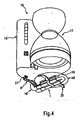
- Fig. 4 shows an exemplary embodiment of an electrical appliance according to the invention, which represents an electrical appliance, in particular a coffee machine 15.
- the coffee machine 15 has a liquid supply 16, a liquid storage 17, a holding surface 18, a line 19 and a heating module 1.
- a cold liquid for. As water, from the liquid supply 16 through the line 19 to the heating module 1. While the liquid flows through the heating module 1, it is heated.
- the liquid heated by the heating module 1 flows from the heating module 1 through the conduit 19 to the hot-liquid reservoir 17.
- Below the hot-fluid reservoir 17 is disposed a hot plate 18 by which the liquid in the hot-liquid reservoir 17 is kept warm. Under the hot plate 18, the heating module 1 is mounted with a spring element 20.
- a heating surface 10 of the heating module 1 is pressed against the hot plate 18 and outputs heat energy to them.
- the heating module 1 is connected via contact lines 8 to a voltage source.
- the contact lines 8 can for easy connection to the voltage source with Connection elements 21, for example, a standard connector, be executed.
- the liquid supply system 16 shown by way of example can also be connected to the line 19 of the coffee machine 15 directly to a liquid source (not shown), eg a water supply line.
- the heating module 1 assumes both the function of heating a continuous liquid and the function of heat energy supply of a hot plate 18.
- the heat output to be applied by the heating module 1 is very different, when heating the liquid about 600 W and heating the hot plate 18 in about 60 W.
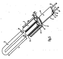
- Fig. 5 shows an exploded view of an embodiment of the heating module according to the invention 1. Based on Fig. 5 In the following, a manufacturing method for the heating module 1 according to the invention will be described.
- Extruded profile 2 shown by way of example is made with three cavities 4 ', 11'.
- the heating element 3 is inserted.
- the heating element 3 has been pre-assembled prior to insertion into the extruded profile 2 by forming a stack comprising the at least one PTC element 5, two electrode body 6 and an insulating member 7.
- the heating element 3 is pressed in the cavity 4 '.
- a suitable tool eg. As a pair of pliers, the extruded profile 2 in the pre-weakened area of a Presswulstes 9 in a pressing direction P together.
- the air gap P 2 of the Presswulstes 9 is thereby reduced.
- the plastic deformation of the pre-weakened extruded profile 2 in the region of the press bead 9 is continued until the heating element 3 is pressed into the cavity 4 '.
- a pipe 12 has been bent prior to assembly of the heating module according to the invention in a U-shaped form.
- the two legs of the U-shaped pipe 12 are inserted into the other two cavities 11 'of the extruded profile 2.
- the length L 1 of the pipe 12 is greater than the length L 2 of the extruded profile 2, whereby the pipe ends 14 of the pipe 12 protrude after insertion from the extruded profile 2 and thereby form connection means for the supply and discharge of the fluid.
- the pipe 12 is pressed in the extruded profile 2.
- the upper Presswülste 13 with a suitable tool, for. As a pair of pliers, compressed on both sides in a pressing direction P.
- the heating element 3 and the pipes 12 can also be pressed in one step in the extruded profile.
- the various Presswülste 9, 13 are compressed in the pressing direction P.
Landscapes
- Engineering & Computer Science (AREA)
- Food Science & Technology (AREA)
- Resistance Heating (AREA)
- Instantaneous Water Boilers, Portable Hot-Water Supply Apparatuses, And Control Of Portable Hot-Water Supply Apparatuses (AREA)
- Pipe Accessories (AREA)
Claims (25)
- Module de chauffage (1) à intégrer dans un appareil électrique, par exemple dans un appareil électroménager tel qu'une cafetière électrique ou un appareil de laboratoire, comprenant au moins une surface de chauffe (10) formée par un profilé (2) et un élément chauffant (3), qui comprend au moins un élément CTP (5) et qui est maintenu par compression dans le profilé (2), ainsi qu'un chauffe-eau instantané intégré dans le module de chauffage (1), qui présente au moins un canal (11) formé dans le profilé (2) et réalisé de manière à pouvoir être traversé par un fluide, caractérisé en ce que le profilé (2) est réalisé sous forme de profilé extrudé (2) et en ce qu'une conduite (12) pouvant être traversée par le fluide est maintenue par compression dans le canal (11) sans espace d'air, le canal (11) étant pressé autour de la conduite (12).
- Module de chauffage (1) selon la revendication 1, caractérisé en ce que le profilé extrudé (2) présente un autre espace creux (4') séparé du au moins un canal (11) et en ce que l'élément chauffant (3) est maintenu par compression dans l'autre espace creux (4').
- Module de chauffage (1) selon la revendication 1 ou 2, caractérisé en ce que le canal (11) est essentiellement rectiligne.
- Module de chauffage (1) selon l'une quelconque des revendications précédentes, caractérisé en ce que le sens d'écoulement principal (H) du fluide à travers le canal (11) est essentiellement rectiligne.
- Module de chauffage (1) selon l'une quelconque des revendications précédentes, caractérisé en ce que le profilé extrudé (2) est fabriqué à partir d'un métal, de préférence l'aluminium.
- Module de chauffage (1) selon l'une quelconque des revendications précédentes, caractérisé en ce que le profilé extrudé (2) est réalisé, au moins sur un côté du logement (4), sous la forme d'un bourrelet de compression (13) essentiellement en forme de U.
- Module de chauffage (1) selon l'une quelconque des revendications précédentes, caractérisé en ce que la surface rayonnante (W) de l'élément chauffant (3) et la surface de chauffe (10) formée par le profilé extrudé (2) ont essentiellement la même taille.
- Module de chauffage (1) selon l'une quelconque des revendications précédentes, caractérisé en ce que le au moins un canal (11), la au moins une surface de chauffe (10) et l'élément chauffant (3) sont disposés les uns sur les autres essentiellement verticalement par rapport à la surface de chauffe (10).
- Module de chauffage (1) selon l'une quelconque des revendications précédentes, caractérisé en ce que la conduite (12) est essentiellement plus longue que le canal (11).
- Module de chauffage (1) selon l'une quelconque des revendications précédentes, caractérisé en ce que la conduite (12) est fabriquée à partir d'un matériau thermoconducteur, de préférence l'aluminium.
- Module de chauffage (1) selon l'une quelconque des revendications précédentes, caractérisé en ce que la conduite (12) est fabriquée à partir d'un matériau résistant à la corrosion.
- Module de chauffage (1) selon l'une quelconque des revendications précédentes, caractérisé en ce que le canal (11) présente un côté entrée et un côté sortie, et le côté entrée et le côté sortie sont disposés du même côté du module de chauffage (1).
- Module de chauffage (1) selon l'une quelconque des revendications précédentes, caractérisé en ce que l'élément chauffant (3) est disposé entre le au moins un canal (11) et la au moins une surface de chauffe (10).
- Module de chauffage (1) selon l'une quelconque des revendications précédentes, caractérisé en ce qu'un bourrelet de compression (13) essentiellement en forme de U est formé sur le au moins un canal (11).
- Module de chauffage (1) selon l'une quelconque des revendications précédentes, caractérisé en ce que l'élément chauffant (3) comprend deux corps d'électrode (6) qui forment un empilement conjointement avec le au moins un élément CTP (5) intercalé.
- Module de chauffage (1) selon la revendication 15, caractérisé en ce que les corps d'électrode (6) présentent chacun un élément de contact (6') par l'intermédiaire duquel les corps d'électrode (6) peuvent être raccordés à une source de tension.
- Module de chauffage (1) selon l'une quelconque des revendications précédentes, caractérisé en ce que l'élément chauffant (3) comprend au moins un élément isolant (7) qui entoure l'empilement formé par le au moins un élément CTP (5) et les deux corps d'électrode (6) en l'isolant électriquement.
- Module de chauffage (1) selon l'une quelconque des revendications précédentes, caractérisé en ce que l'élément chauffant (3) est isolé électriquement du profilé extrudé (2) grâce à l'intercalage d'un élément isolant (7).
- Module de chauffage (1) selon la revendication 17 ou 18, caractérisé en ce que l'élément isolant (7) est fabriqué à partir d'une feuille de matière plastique thermoconductrice, de préférence une feuille de polyimide.
- Appareil électrique, en particulier cafetière électrique (15) ou appareil de laboratoire, comprenant un réservoir de liquide (17), une plaque chauffante (18) et une tuyauterie (19), caractérisé en ce que l'appareil électrique contient un module de chauffage (1) selon l'une quelconque des revendications 1 à 19, dans lequel la surface de chauffe (10) du module de chauffage (1) est reliée de manière thermoconductrice à la plaque chauffante (18).
- Appareil électrique selon la revendication 20, caractérisé en ce que l'appareil électrique comprend un élément de ressort (20) sous l'action duquel le module de chauffage (1) est pressé contre la plaque chauffante (18).
- Procédé de fabrication d'un module de chauffage (1) permettant de chauffer des liquides en circulation et de chauffer en même temps une surface de chauffe (10) intégrée, comprenant les étapes de procédé suivantes :- fournir un profilé extrudé (2) comprenant au moins deux espaces creux (4', 11') séparés l'un de l'autre et une surface de chauffe (10),- introduire un élément chauffant (3) comprenant un élément CTP dans l'un des espaces creux (4') du profilé extrudé (2),- maintenir par compression l'élément chauffant (3) dans l'espace creux (4') par déformation plastique du profilé extrudé (2),- introduire au moins une conduite (12) pouvant être traversée par un fluide dans au moins un autre des espaces creux (11'),- former un canal (11) par déformation plastique de la section de l'autre espace creux (11') autour de la conduite (12).
- Procédé selon la revendication 22, caractérisé par l'étape de procédé suivante :- plier la conduite (12) selon une forme essentiellement en U avant de l'introduire dans deux autres espaces creux.
- Procédé selon la revendication 23, caractérisé par l'étape de procédé suivante :- introduire les deux branches de la conduite (12) pliée en forme de U dans d'autres espaces creux du profilé extrudé (2) séparés les uns des autres avant de former les canaux (11).
- Procédé selon les revendications 22 à 24, caractérisé par l'étape de procédé suivante :- monter au préalable l'élément chauffant (3) en formant un empilement comprenant au moins un élément CTP (5), deux corps d'électrode (6) et au moins un élément isolant (7) avant de l'introduire dans le profilé extrudé (2).
Priority Applications (5)
| Application Number | Priority Date | Filing Date | Title |
|---|---|---|---|
| AT03025226T ATE317238T1 (de) | 2003-11-05 | 2003-11-05 | Heizmodul mit heizfläche und durchlauferhitzer und verfahren zu seiner herstellung |
| EP03025226A EP1529470B2 (fr) | 2003-11-05 | 2003-11-05 | Module de chauffage avec surface chauffante et chaudière instantanée et procédé pour sa fabrication |
| DE50302373T DE50302373D1 (de) | 2003-11-05 | 2003-11-05 | Heizmodul mit Heizfläche und Durchlauferhitzer und Verfahren zu seiner Herstellung |
| PCT/EP2004/011664 WO2005046410A1 (fr) | 2003-11-05 | 2004-10-15 | Module de chauffage comprenant une surface chauffante et un dispositif de chauffage en continu, et procede de realisation |
| US10/578,307 US7865073B2 (en) | 2003-11-05 | 2004-10-15 | Heating module comprising a heating surface, flow heater, and method for the production thereof |
Applications Claiming Priority (1)
| Application Number | Priority Date | Filing Date | Title |
|---|---|---|---|
| EP03025226A EP1529470B2 (fr) | 2003-11-05 | 2003-11-05 | Module de chauffage avec surface chauffante et chaudière instantanée et procédé pour sa fabrication |
Publications (3)
| Publication Number | Publication Date |
|---|---|
| EP1529470A1 EP1529470A1 (fr) | 2005-05-11 |
| EP1529470B1 EP1529470B1 (fr) | 2006-02-08 |
| EP1529470B2 true EP1529470B2 (fr) | 2010-12-29 |
Family
ID=34429258
Family Applications (1)
| Application Number | Title | Priority Date | Filing Date |
|---|---|---|---|
| EP03025226A Expired - Lifetime EP1529470B2 (fr) | 2003-11-05 | 2003-11-05 | Module de chauffage avec surface chauffante et chaudière instantanée et procédé pour sa fabrication |
Country Status (5)
| Country | Link |
|---|---|
| US (1) | US7865073B2 (fr) |
| EP (1) | EP1529470B2 (fr) |
| AT (1) | ATE317238T1 (fr) |
| DE (1) | DE50302373D1 (fr) |
| WO (1) | WO2005046410A1 (fr) |
Cited By (1)
| Publication number | Priority date | Publication date | Assignee | Title |
|---|---|---|---|---|
| US10775075B2 (en) | 2014-12-22 | 2020-09-15 | Horiba Stec, Co., Ltd. | Fluid heater |
Families Citing this family (15)
| Publication number | Priority date | Publication date | Assignee | Title |
|---|---|---|---|---|
| DE102005050203B4 (de) * | 2005-10-18 | 2018-05-24 | Eichenauer Heizelemente Gmbh & Co. Kg | Verfahren zur Herstellung eines Durchflusserhitzers und Durchflusserhitzer |
| US7456374B2 (en) | 2006-07-27 | 2008-11-25 | Air Products And Chemicals, Inc. | Component heater |
| IT1397383B1 (it) * | 2010-01-11 | 2013-01-10 | Swiss Caffe Asia Ltd | Scambiatore di calore per macchine per infusi e simili, particolarmente per il riscaldamento dell'acqua per la preparazione di caffe' espresso. |
| DE202010010779U1 (de) | 2010-07-28 | 2010-11-11 | Dbk David + Baader Gmbh | Durchlauferhitzer |
| DE102011007542B4 (de) * | 2011-04-15 | 2023-01-12 | Eichenauer Heizelemente Gmbh & Co. Kg | Durchlauferhitzer |
| US8822892B2 (en) * | 2011-10-20 | 2014-09-02 | Shanghai Huazu Industry Co., Ltd. | Combined metal PTC rapid electric heater |
| BE1020669A5 (fr) | 2012-01-04 | 2014-03-04 | Zelitec Group S A R L | Dispositif de prechauffage de fluide notamment de fluide refroidissement de moteur a combustion. |
| WO2014087272A1 (fr) * | 2012-10-26 | 2014-06-12 | Koninklijke Philips N.V. | Appareil de fabrication de boisson comprenant au moins un tube pour transporter un liquide |
| US11002465B2 (en) * | 2014-09-24 | 2021-05-11 | Bestway Inflatables & Materials Corp. | PTC heater |
| CN204119542U (zh) | 2014-09-24 | 2015-01-21 | 上海荣威塑胶工业有限公司 | 一种ptc加热器 |
| CN110301826B (zh) * | 2018-03-20 | 2025-01-10 | 广州胜维电器制造有限公司 | 发热部 |
| ES2880292T5 (en) | 2018-08-16 | 2025-12-03 | Cup&Cino Kaffeesystem Vertrieb Gmbh & Co Kg | Coffee machine for preparing a hot drink |
| KR102055678B1 (ko) * | 2018-10-11 | 2019-12-13 | 엘지전자 주식회사 | 정수기 |
| IT202000031001A1 (it) * | 2020-12-16 | 2022-06-16 | Irca Spa | Riscaldatore elettrico per macchina per la preparazione di bevande calde |
| DE102021104680A1 (de) * | 2021-02-26 | 2022-09-01 | Eberspächer Catem Gmbh & Co. Kg | Elektrische Heizvorrichtung |
Citations (3)
| Publication number | Priority date | Publication date | Assignee | Title |
|---|---|---|---|---|
| DE7909979U1 (de) † | 1979-04-05 | 1979-07-05 | Siemens Ag, 1000 Berlin Und 8000 Muenchen | Elektrischer durchlauferhitzer mit aus kaltleitendem keramischem material bestehenden heizelementen |
| DE7912211U1 (de) † | 1979-04-26 | 1979-07-26 | Siemens Ag, 1000 Berlin Und 8000 Muenchen | Heizeinrichtung zum erwaermen von heizoel |
| DE4240840A1 (de) † | 1992-12-04 | 1994-06-09 | Tuerk & Hillinger Gmbh | Elektrischer Durchlauferhitzer für Flüssigkeiten |
Family Cites Families (11)
| Publication number | Priority date | Publication date | Assignee | Title |
|---|---|---|---|---|
| DE2537769A1 (de) | 1975-08-25 | 1977-03-10 | Elpag Ag Chur | Durchlauferhitzer |
| DE2804818C2 (de) | 1978-02-04 | 1986-12-11 | Fritz Eichenauer GmbH & Co KG, 6744 Kandel | Elektrische Heizeinrichtung |
| DE2804784A1 (de) * | 1978-02-04 | 1979-08-09 | Eichenauer Fa Fritz | Elektrische widerstandsheizeinrichtung |
| DE2948591A1 (de) * | 1979-12-03 | 1981-06-11 | Fa. Fritz Eichenauer, 6744 Kandel | Durchlauferhitzer |
| US4870249A (en) * | 1987-05-26 | 1989-09-26 | Texas Instruments Incorporated | Electric fuel heating device |
| EP0573691B1 (fr) * | 1992-06-11 | 1997-01-08 | David & Baader DBK Spezialfabrik elektrischer Apparate und Heizwiderstände GmbH | Méthode pour produire une résistance chauffante à coefficient de température positif |
| US5724478A (en) * | 1996-05-14 | 1998-03-03 | Truheat Corporation | Liquid heater assembly |
| US6442341B1 (en) | 2000-11-27 | 2002-08-27 | Chia-Hsiung Wu | Simple-type fluid heating tube structural arrangement |
| US20020185867A1 (en) * | 2001-06-08 | 2002-12-12 | Stachowiak Robert S. | Water heater connection system |
| US6817279B2 (en) * | 2002-09-27 | 2004-11-16 | Simatelex Manufactory Co., Ltd. | Method of making coffee and coffee maker |
| JP4029092B2 (ja) * | 2004-10-26 | 2008-01-09 | 日本ピラー工業株式会社 | 流体用ヒータ及び流体加熱装置 |
-
2003
- 2003-11-05 AT AT03025226T patent/ATE317238T1/de not_active IP Right Cessation
- 2003-11-05 EP EP03025226A patent/EP1529470B2/fr not_active Expired - Lifetime
- 2003-11-05 DE DE50302373T patent/DE50302373D1/de not_active Expired - Lifetime
-
2004
- 2004-10-15 US US10/578,307 patent/US7865073B2/en not_active Expired - Fee Related
- 2004-10-15 WO PCT/EP2004/011664 patent/WO2005046410A1/fr not_active Ceased
Patent Citations (3)
| Publication number | Priority date | Publication date | Assignee | Title |
|---|---|---|---|---|
| DE7909979U1 (de) † | 1979-04-05 | 1979-07-05 | Siemens Ag, 1000 Berlin Und 8000 Muenchen | Elektrischer durchlauferhitzer mit aus kaltleitendem keramischem material bestehenden heizelementen |
| DE7912211U1 (de) † | 1979-04-26 | 1979-07-26 | Siemens Ag, 1000 Berlin Und 8000 Muenchen | Heizeinrichtung zum erwaermen von heizoel |
| DE4240840A1 (de) † | 1992-12-04 | 1994-06-09 | Tuerk & Hillinger Gmbh | Elektrischer Durchlauferhitzer für Flüssigkeiten |
Cited By (1)
| Publication number | Priority date | Publication date | Assignee | Title |
|---|---|---|---|---|
| US10775075B2 (en) | 2014-12-22 | 2020-09-15 | Horiba Stec, Co., Ltd. | Fluid heater |
Also Published As
| Publication number | Publication date |
|---|---|
| EP1529470A1 (fr) | 2005-05-11 |
| US7865073B2 (en) | 2011-01-04 |
| EP1529470B1 (fr) | 2006-02-08 |
| WO2005046410A1 (fr) | 2005-05-26 |
| ATE317238T1 (de) | 2006-02-15 |
| DE50302373D1 (de) | 2006-04-20 |
| US20080037969A1 (en) | 2008-02-14 |
Similar Documents
| Publication | Publication Date | Title |
|---|---|---|
| EP1529470B2 (fr) | Module de chauffage avec surface chauffante et chaudière instantanée et procédé pour sa fabrication | |
| DE2948591C2 (fr) | ||
| DE4433814B4 (de) | Kraftfahrzeug | |
| DE102012107600B4 (de) | Elektrische Heizvorrichtung zum Beheizen von Fluiden | |
| EP2592982B1 (fr) | Dispositif de chauffe instantané dynamique | |
| EP3273177B1 (fr) | Dispositif de chauffage électrique | |
| DE2804749C3 (de) | Durchlauferhitzer | |
| EP2295886A2 (fr) | Dispositif de chauffage de liquides | |
| EP2410813B1 (fr) | Radiateur électrique et chauffe-eau instantané | |
| EP1777452B1 (fr) | Connecteur chauffable | |
| EP1847786A1 (fr) | Appareil de chauffage | |
| EP1557601B1 (fr) | Clip de chauffage pour une conduite de fluide | |
| DE102022125856A1 (de) | Elektrischer Heizer zur Erwärmung eines Fluids | |
| DE102011007542A1 (de) | Durchlauferhitzer | |
| EP2145783A2 (fr) | Chauffage de véhicule | |
| DE102006055216A1 (de) | Heizeinrichtung für Dieselkraftstoff und beheizbares Dieselfiltersystem | |
| EP3557155A1 (fr) | Dispositif de chauffage électrique | |
| EP2092863B1 (fr) | Chauffe-eau instantané | |
| EP1715175B1 (fr) | Dispositif de chauffage pour un élément gazeux ou un élément liquide à chauffer | |
| DE102009033988A1 (de) | Heizvorrichtung | |
| DE102019202045A1 (de) | Elektrische Heizvorrichtung | |
| DE102011013972A1 (de) | Elektrisches Haustechnik-Heizgerät | |
| WO2012080417A1 (fr) | Module thermoélectrique et utilisation d'un module thermoélectrique | |
| EP1947908A1 (fr) | Agencement de filament chauffant destiné au chauffage de matières gazeuses s'écoulant | |
| DE2521863A1 (de) | Waermetauscher fuer kuehlmoebel |
Legal Events
| Date | Code | Title | Description |
|---|---|---|---|
| PUAI | Public reference made under article 153(3) epc to a published international application that has entered the european phase |
Free format text: ORIGINAL CODE: 0009012 |
|
| 17P | Request for examination filed |
Effective date: 20040618 |
|
| AK | Designated contracting states |
Kind code of ref document: A1 Designated state(s): AT BE BG CH CY CZ DE DK EE ES FI FR GB GR HU IE IT LI LU MC NL PT RO SE SI SK TR |
|
| AX | Request for extension of the european patent |
Extension state: AL LT LV MK |
|
| GRAP | Despatch of communication of intention to grant a patent |
Free format text: ORIGINAL CODE: EPIDOSNIGR1 |
|
| GRAS | Grant fee paid |
Free format text: ORIGINAL CODE: EPIDOSNIGR3 |
|
| GRAA | (expected) grant |
Free format text: ORIGINAL CODE: 0009210 |
|
| AKX | Designation fees paid |
Designated state(s): AT BE BG CH CY CZ DE DK EE ES FI FR GB GR HU IE IT LI LU MC NL PT RO SE SI SK TR |
|
| AK | Designated contracting states |
Kind code of ref document: B1 Designated state(s): AT BE BG CH CY CZ DE DK EE ES FI FR GB GR HU IE IT LI LU MC NL PT RO SE SI SK TR |
|
| PG25 | Lapsed in a contracting state [announced via postgrant information from national office to epo] |
Ref country code: IT Free format text: LAPSE BECAUSE OF FAILURE TO SUBMIT A TRANSLATION OF THE DESCRIPTION OR TO PAY THE FEE WITHIN THE PRESCRIBED TIME-LIMIT;WARNING: LAPSES OF ITALIAN PATENTS WITH EFFECTIVE DATE BEFORE 2007 MAY HAVE OCCURRED AT ANY TIME BEFORE 2007. THE CORRECT EFFECTIVE DATE MAY BE DIFFERENT FROM THE ONE RECORDED. Effective date: 20060208 Ref country code: SI Free format text: LAPSE BECAUSE OF FAILURE TO SUBMIT A TRANSLATION OF THE DESCRIPTION OR TO PAY THE FEE WITHIN THE PRESCRIBED TIME-LIMIT Effective date: 20060208 Ref country code: FI Free format text: LAPSE BECAUSE OF FAILURE TO SUBMIT A TRANSLATION OF THE DESCRIPTION OR TO PAY THE FEE WITHIN THE PRESCRIBED TIME-LIMIT Effective date: 20060208 Ref country code: NL Free format text: LAPSE BECAUSE OF FAILURE TO SUBMIT A TRANSLATION OF THE DESCRIPTION OR TO PAY THE FEE WITHIN THE PRESCRIBED TIME-LIMIT Effective date: 20060208 Ref country code: RO Free format text: LAPSE BECAUSE OF FAILURE TO SUBMIT A TRANSLATION OF THE DESCRIPTION OR TO PAY THE FEE WITHIN THE PRESCRIBED TIME-LIMIT Effective date: 20060208 Ref country code: SK Free format text: LAPSE BECAUSE OF FAILURE TO SUBMIT A TRANSLATION OF THE DESCRIPTION OR TO PAY THE FEE WITHIN THE PRESCRIBED TIME-LIMIT Effective date: 20060208 Ref country code: IE Free format text: LAPSE BECAUSE OF FAILURE TO SUBMIT A TRANSLATION OF THE DESCRIPTION OR TO PAY THE FEE WITHIN THE PRESCRIBED TIME-LIMIT Effective date: 20060208 |
|
| REG | Reference to a national code |
Ref country code: GB Ref legal event code: FG4D Free format text: NOT ENGLISH |
|
| REG | Reference to a national code |
Ref country code: CH Ref legal event code: EP |
|
| REG | Reference to a national code |
Ref country code: IE Ref legal event code: FG4D Free format text: LANGUAGE OF EP DOCUMENT: GERMAN |
|
| REF | Corresponds to: |
Ref document number: 50302373 Country of ref document: DE Date of ref document: 20060420 Kind code of ref document: P |
|
| PG25 | Lapsed in a contracting state [announced via postgrant information from national office to epo] |
Ref country code: DK Free format text: LAPSE BECAUSE OF FAILURE TO SUBMIT A TRANSLATION OF THE DESCRIPTION OR TO PAY THE FEE WITHIN THE PRESCRIBED TIME-LIMIT Effective date: 20060508 Ref country code: BG Free format text: LAPSE BECAUSE OF FAILURE TO SUBMIT A TRANSLATION OF THE DESCRIPTION OR TO PAY THE FEE WITHIN THE PRESCRIBED TIME-LIMIT Effective date: 20060508 Ref country code: SE Free format text: LAPSE BECAUSE OF FAILURE TO SUBMIT A TRANSLATION OF THE DESCRIPTION OR TO PAY THE FEE WITHIN THE PRESCRIBED TIME-LIMIT Effective date: 20060508 |
|
| PG25 | Lapsed in a contracting state [announced via postgrant information from national office to epo] |
Ref country code: ES Free format text: LAPSE BECAUSE OF FAILURE TO SUBMIT A TRANSLATION OF THE DESCRIPTION OR TO PAY THE FEE WITHIN THE PRESCRIBED TIME-LIMIT Effective date: 20060519 |
|
| GBT | Gb: translation of ep patent filed (gb section 77(6)(a)/1977) |
Effective date: 20060524 |
|
| NLV1 | Nl: lapsed or annulled due to failure to fulfill the requirements of art. 29p and 29m of the patents act | ||
| PG25 | Lapsed in a contracting state [announced via postgrant information from national office to epo] |
Ref country code: PT Free format text: LAPSE BECAUSE OF FAILURE TO SUBMIT A TRANSLATION OF THE DESCRIPTION OR TO PAY THE FEE WITHIN THE PRESCRIBED TIME-LIMIT Effective date: 20060710 |
|
| REG | Reference to a national code |
Ref country code: IE Ref legal event code: FD4D |
|
| ET | Fr: translation filed | ||
| PLBI | Opposition filed |
Free format text: ORIGINAL CODE: 0009260 |
|
| 26 | Opposition filed |
Opponent name: EICHENAUER HEIZELEMENTE GMBH & CO. KG Effective date: 20061020 |
|
| PG25 | Lapsed in a contracting state [announced via postgrant information from national office to epo] |
Ref country code: BE Free format text: LAPSE BECAUSE OF NON-PAYMENT OF DUE FEES Effective date: 20061130 Ref country code: MC Free format text: LAPSE BECAUSE OF NON-PAYMENT OF DUE FEES Effective date: 20061130 |
|
| PLAX | Notice of opposition and request to file observation + time limit sent |
Free format text: ORIGINAL CODE: EPIDOSNOBS2 |
|
| PLAB | Opposition data, opponent's data or that of the opponent's representative modified |
Free format text: ORIGINAL CODE: 0009299OPPO |
|
| R26 | Opposition filed (corrected) |
Opponent name: EICHENAUER HEIZELEMENTE GMBH & CO. KG Effective date: 20061020 |
|
| PLAF | Information modified related to communication of a notice of opposition and request to file observations + time limit |
Free format text: ORIGINAL CODE: EPIDOSCOBS2 |
|
| PLBB | Reply of patent proprietor to notice(s) of opposition received |
Free format text: ORIGINAL CODE: EPIDOSNOBS3 |
|
| BERE | Be: lapsed |
Owner name: DBK DAVID + BAADER G.M.B.H. Effective date: 20061130 |
|
| PLAY | Examination report in opposition despatched + time limit |
Free format text: ORIGINAL CODE: EPIDOSNORE2 |
|
| PG25 | Lapsed in a contracting state [announced via postgrant information from national office to epo] |
Ref country code: AT Free format text: LAPSE BECAUSE OF NON-PAYMENT OF DUE FEES Effective date: 20061105 |
|
| PLBC | Reply to examination report in opposition received |
Free format text: ORIGINAL CODE: EPIDOSNORE3 |
|
| PG25 | Lapsed in a contracting state [announced via postgrant information from national office to epo] |
Ref country code: CZ Free format text: LAPSE BECAUSE OF FAILURE TO SUBMIT A TRANSLATION OF THE DESCRIPTION OR TO PAY THE FEE WITHIN THE PRESCRIBED TIME-LIMIT Effective date: 20060208 Ref country code: GR Free format text: LAPSE BECAUSE OF FAILURE TO SUBMIT A TRANSLATION OF THE DESCRIPTION OR TO PAY THE FEE WITHIN THE PRESCRIBED TIME-LIMIT Effective date: 20060509 |
|
| RIN2 | Information on inventor provided after grant (corrected) |
Inventor name: MUIRHEAD, WILLIAM Inventor name: VON DER LUEHE, FRIEDRICH |
|
| PG25 | Lapsed in a contracting state [announced via postgrant information from national office to epo] |
Ref country code: EE Free format text: LAPSE BECAUSE OF FAILURE TO SUBMIT A TRANSLATION OF THE DESCRIPTION OR TO PAY THE FEE WITHIN THE PRESCRIBED TIME-LIMIT Effective date: 20060208 |
|
| PG25 | Lapsed in a contracting state [announced via postgrant information from national office to epo] |
Ref country code: LI Free format text: LAPSE BECAUSE OF NON-PAYMENT OF DUE FEES Effective date: 20071130 Ref country code: LU Free format text: LAPSE BECAUSE OF NON-PAYMENT OF DUE FEES Effective date: 20061105 Ref country code: CH Free format text: LAPSE BECAUSE OF NON-PAYMENT OF DUE FEES Effective date: 20071130 Ref country code: TR Free format text: LAPSE BECAUSE OF FAILURE TO SUBMIT A TRANSLATION OF THE DESCRIPTION OR TO PAY THE FEE WITHIN THE PRESCRIBED TIME-LIMIT Effective date: 20060208 Ref country code: HU Free format text: LAPSE BECAUSE OF FAILURE TO SUBMIT A TRANSLATION OF THE DESCRIPTION OR TO PAY THE FEE WITHIN THE PRESCRIBED TIME-LIMIT Effective date: 20060809 |
|
| REG | Reference to a national code |
Ref country code: CH Ref legal event code: PL |
|
| PG25 | Lapsed in a contracting state [announced via postgrant information from national office to epo] |
Ref country code: CY Free format text: LAPSE BECAUSE OF FAILURE TO SUBMIT A TRANSLATION OF THE DESCRIPTION OR TO PAY THE FEE WITHIN THE PRESCRIBED TIME-LIMIT Effective date: 20060208 |
|
| APBM | Appeal reference recorded |
Free format text: ORIGINAL CODE: EPIDOSNREFNO |
|
| APBP | Date of receipt of notice of appeal recorded |
Free format text: ORIGINAL CODE: EPIDOSNNOA2O |
|
| APAH | Appeal reference modified |
Free format text: ORIGINAL CODE: EPIDOSCREFNO |
|
| APBQ | Date of receipt of statement of grounds of appeal recorded |
Free format text: ORIGINAL CODE: EPIDOSNNOA3O |
|
| APBU | Appeal procedure closed |
Free format text: ORIGINAL CODE: EPIDOSNNOA9O |
|
| PUAH | Patent maintained in amended form |
Free format text: ORIGINAL CODE: 0009272 |
|
| STAA | Information on the status of an ep patent application or granted ep patent |
Free format text: STATUS: PATENT MAINTAINED AS AMENDED |
|
| 27A | Patent maintained in amended form |
Effective date: 20101229 |
|
| AK | Designated contracting states |
Kind code of ref document: B2 Designated state(s): AT BE BG CH CY CZ DE DK EE ES FI FR GB GR HU IE IT LI LU MC NL PT RO SE SI SK TR |
|
| PGFP | Annual fee paid to national office [announced via postgrant information from national office to epo] |
Ref country code: DE Payment date: 20101029 Year of fee payment: 8 |
|
| PGFP | Annual fee paid to national office [announced via postgrant information from national office to epo] |
Ref country code: IT Payment date: 20101126 Year of fee payment: 8 Ref country code: GB Payment date: 20101123 Year of fee payment: 8 |
|
| PGFP | Annual fee paid to national office [announced via postgrant information from national office to epo] |
Ref country code: FR Payment date: 20111125 Year of fee payment: 9 |
|
| GBPC | Gb: european patent ceased through non-payment of renewal fee |
Effective date: 20121105 |
|
| REG | Reference to a national code |
Ref country code: FR Ref legal event code: ST Effective date: 20130731 |
|
| PG25 | Lapsed in a contracting state [announced via postgrant information from national office to epo] |
Ref country code: IT Free format text: LAPSE BECAUSE OF NON-PAYMENT OF DUE FEES Effective date: 20121105 |
|
| REG | Reference to a national code |
Ref country code: DE Ref legal event code: R119 Ref document number: 50302373 Country of ref document: DE Effective date: 20130601 |
|
| PG25 | Lapsed in a contracting state [announced via postgrant information from national office to epo] |
Ref country code: DE Free format text: LAPSE BECAUSE OF NON-PAYMENT OF DUE FEES Effective date: 20130601 |
|
| PG25 | Lapsed in a contracting state [announced via postgrant information from national office to epo] |
Ref country code: FR Free format text: LAPSE BECAUSE OF NON-PAYMENT OF DUE FEES Effective date: 20121130 Ref country code: GB Free format text: LAPSE BECAUSE OF NON-PAYMENT OF DUE FEES Effective date: 20121105 |