EP2145783A2 - Chauffage de véhicule - Google Patents
Chauffage de véhicule Download PDFInfo
- Publication number
- EP2145783A2 EP2145783A2 EP09009245A EP09009245A EP2145783A2 EP 2145783 A2 EP2145783 A2 EP 2145783A2 EP 09009245 A EP09009245 A EP 09009245A EP 09009245 A EP09009245 A EP 09009245A EP 2145783 A2 EP2145783 A2 EP 2145783A2
- Authority
- EP
- European Patent Office
- Prior art keywords
- heating
- contact plates
- heat exchanger
- heater according
- vehicle
- Prior art date
- Legal status (The legal status is an assumption and is not a legal conclusion. Google has not performed a legal analysis and makes no representation as to the accuracy of the status listed.)
- Granted
Links
- 238000010438 heat treatment Methods 0.000 claims abstract description 63
- 238000004519 manufacturing process Methods 0.000 description 5
- 239000000919 ceramic Substances 0.000 description 4
- 238000001125 extrusion Methods 0.000 description 4
- 238000009413 insulation Methods 0.000 description 4
- 238000011161 development Methods 0.000 description 3
- 230000018109 developmental process Effects 0.000 description 3
- 239000000463 material Substances 0.000 description 3
- 239000004033 plastic Substances 0.000 description 3
- 229920003223 poly(pyromellitimide-1,4-diphenyl ether) Polymers 0.000 description 3
- 230000008878 coupling Effects 0.000 description 2
- 238000010168 coupling process Methods 0.000 description 2
- 238000005859 coupling reaction Methods 0.000 description 2
- 238000010292 electrical insulation Methods 0.000 description 2
- 239000012530 fluid Substances 0.000 description 2
- 239000011888 foil Substances 0.000 description 2
- 239000002184 metal Substances 0.000 description 2
- 229910052751 metal Inorganic materials 0.000 description 2
- 239000004952 Polyamide Substances 0.000 description 1
- 238000004026 adhesive bonding Methods 0.000 description 1
- 229910052782 aluminium Inorganic materials 0.000 description 1
- XAGFODPZIPBFFR-UHFFFAOYSA-N aluminium Chemical compound [Al] XAGFODPZIPBFFR-UHFFFAOYSA-N 0.000 description 1
- 230000009286 beneficial effect Effects 0.000 description 1
- 238000010276 construction Methods 0.000 description 1
- 230000007547 defect Effects 0.000 description 1
- 230000001419 dependent effect Effects 0.000 description 1
- 230000005611 electricity Effects 0.000 description 1
- 230000017525 heat dissipation Effects 0.000 description 1
- 238000002347 injection Methods 0.000 description 1
- 239000007924 injection Substances 0.000 description 1
- 238000003475 lamination Methods 0.000 description 1
- 238000000034 method Methods 0.000 description 1
- 210000001331 nose Anatomy 0.000 description 1
- 238000005192 partition Methods 0.000 description 1
- 239000002985 plastic film Substances 0.000 description 1
- 229920006255 plastic film Polymers 0.000 description 1
- 229920002647 polyamide Polymers 0.000 description 1
- 229920000642 polymer Polymers 0.000 description 1
- 238000004080 punching Methods 0.000 description 1
- 238000005476 soldering Methods 0.000 description 1
- 238000011144 upstream manufacturing Methods 0.000 description 1
Images


Classifications
-
- B—PERFORMING OPERATIONS; TRANSPORTING
- B60—VEHICLES IN GENERAL
- B60H—ARRANGEMENTS OF HEATING, COOLING, VENTILATING OR OTHER AIR-TREATING DEVICES SPECIALLY ADAPTED FOR PASSENGER OR GOODS SPACES OF VEHICLES
- B60H1/00—Heating, cooling or ventilating [HVAC] devices
- B60H1/22—Heating, cooling or ventilating [HVAC] devices the heat being derived otherwise than from the propulsion plant
- B60H1/2215—Heating, cooling or ventilating [HVAC] devices the heat being derived otherwise than from the propulsion plant the heat being derived from electric heaters
- B60H1/2225—Heating, cooling or ventilating [HVAC] devices the heat being derived otherwise than from the propulsion plant the heat being derived from electric heaters arrangements of electric heaters for heating air
-
- F—MECHANICAL ENGINEERING; LIGHTING; HEATING; WEAPONS; BLASTING
- F24—HEATING; RANGES; VENTILATING
- F24H—FLUID HEATERS, e.g. WATER OR AIR HEATERS, HAVING HEAT-GENERATING MEANS, e.g. HEAT PUMPS, IN GENERAL
- F24H3/00—Air heaters
- F24H3/02—Air heaters with forced circulation
- F24H3/04—Air heaters with forced circulation the air being in direct contact with the heating medium, e.g. electric heating element
- F24H3/0405—Air heaters with forced circulation the air being in direct contact with the heating medium, e.g. electric heating element using electric energy supply, e.g. the heating medium being a resistive element; Heating by direct contact, i.e. with resistive elements, electrodes and fins being bonded together without additional element in-between
- F24H3/0429—For vehicles
-
- F—MECHANICAL ENGINEERING; LIGHTING; HEATING; WEAPONS; BLASTING
- F24—HEATING; RANGES; VENTILATING
- F24H—FLUID HEATERS, e.g. WATER OR AIR HEATERS, HAVING HEAT-GENERATING MEANS, e.g. HEAT PUMPS, IN GENERAL
- F24H9/00—Details
- F24H9/18—Arrangement or mounting of grates or heating means
- F24H9/1854—Arrangement or mounting of grates or heating means for air heaters
- F24H9/1863—Arrangement or mounting of electric heating means
- F24H9/1872—PTC
-
- H—ELECTRICITY
- H05—ELECTRIC TECHNIQUES NOT OTHERWISE PROVIDED FOR
- H05B—ELECTRIC HEATING; ELECTRIC LIGHT SOURCES NOT OTHERWISE PROVIDED FOR; CIRCUIT ARRANGEMENTS FOR ELECTRIC LIGHT SOURCES, IN GENERAL
- H05B3/00—Ohmic-resistance heating
- H05B3/40—Heating elements having the shape of rods or tubes
- H05B3/42—Heating elements having the shape of rods or tubes non-flexible
- H05B3/48—Heating elements having the shape of rods or tubes non-flexible heating conductor embedded in insulating material
- H05B3/50—Heating elements having the shape of rods or tubes non-flexible heating conductor embedded in insulating material heating conductor arranged in metal tubes, the radiating surface having heat-conducting fins
-
- B—PERFORMING OPERATIONS; TRANSPORTING
- B60—VEHICLES IN GENERAL
- B60H—ARRANGEMENTS OF HEATING, COOLING, VENTILATING OR OTHER AIR-TREATING DEVICES SPECIALLY ADAPTED FOR PASSENGER OR GOODS SPACES OF VEHICLES
- B60H1/00—Heating, cooling or ventilating [HVAC] devices
- B60H1/22—Heating, cooling or ventilating [HVAC] devices the heat being derived otherwise than from the propulsion plant
- B60H2001/2268—Constructional features
- B60H2001/2278—Connectors, water supply, housing, mounting brackets
-
- H—ELECTRICITY
- H05—ELECTRIC TECHNIQUES NOT OTHERWISE PROVIDED FOR
- H05B—ELECTRIC HEATING; ELECTRIC LIGHT SOURCES NOT OTHERWISE PROVIDED FOR; CIRCUIT ARRANGEMENTS FOR ELECTRIC LIGHT SOURCES, IN GENERAL
- H05B2203/00—Aspects relating to Ohmic resistive heating covered by group H05B3/00
- H05B2203/022—Heaters specially adapted for heating gaseous material
- H05B2203/023—Heaters of the type used for electrically heating the air blown in a vehicle compartment by the vehicle heating system
Definitions
- the invention relates to a vehicle heating with the features specified in the preamble of claim 1.
- a vehicle heater is for example from the EP 1 768 457 A1 known.
- the from the EP 1 768 457 A1 known vehicle heating has two contact plates between which a positioning frame is arranged with PTC heating elements. The positioning frame is locked with the contact plates.
- Object of the present invention is to show a way how to simplify the production of such a vehicle heating.
- a vehicle device has not only one but two positioning frame that hold the at least one heating element.
- the contact plates can therefore be provided in an upstream production step with the positioning frame.
- the positioning frames engage around the longitudinal edges of the contact plates, for example, by the positioning frames are splashed around the contact plates or the positioning frames are pushed or snapped onto the contact plates.
- the assembly of the vehicle heating can be simplified because it involves fewer components to handle.
- PTC elements, two positioning frames and two contact plates can be preassembled into one unit.
- the contact plates and the positioning frame attached to them can advantageously be of the same design, so that fewer different components are required. This simplifies stock keeping and enables cost savings.
- the positioning frames may form a receptacle for the heating element or the heating elements.
- the heating elements preferably rectangular PTC elements
- a second contact plate which carries a preferably identically formed positioning frame.
- the depth of the positioning frame should be half the thickness of the heating elements or slightly less.
- the positioning frames preferably have clamping noses for clamping the PTC elements.
- Suitable positioning frame can be made of plastic or polymer ceramic and can be snapped onto the contact plates, postponed or sprayed around the contact plates.
- the positioning frame leaves a rear side of the contact plates facing away from the heating elements.
- This back of the contact plates is preferred covered with an electrically insulating pad, for example a strip of Kapton foil or an electrically insulating ceramic.
- an electrically insulating pad for example a strip of Kapton foil or an electrically insulating ceramic.
- several strips of the same or different material can be placed on top of each other.
- contact plates can also be achieved by the material of a positioning frame covering the rear side, for example polyamide. Injection moldable materials, however, usually have the disadvantage of always causing a significant thermal insulation.
- the contact plates are electrically isolated by a separate support, the electrical insulation can be combined with a beneficial higher thermal conductivity and thus better thermal coupling of the heater to the heat exchanger.
- the positioning frames preferably surround the heating elements in a fluid-tight manner.
- the positioning frames can advantageously prevent contact between the fluid to be heated and the heating elements.
- the two positioning of a heater sealingly abut each other. It is also possible that a seal is arranged between the insulating frame.
- the heat exchanger or heat exchangers have heating device receptacles in which the heating devices are arranged.
- the heating device receptacles can be designed, for example, as open channels into which the heating devices or their components are inserted. Such channels may for example have a U-shaped cross-section.
- the heater receptacles preferably have openings in which the heaters are stuck.
- heater receivers By means provided on the heat exchangers heater receivers can be realized a particularly simple and cost-effective production.
- the fixing of the heaters to the heat exchanger can be made in this way namely with little effort.
- the heat exchangers can be used to advantage, the individual elements of the heating devices, namely to keep their contact plates with interposed heating elements together.
- the structure of the heating devices can be simplified, in particular can be dispensed with a costly soldering or gluing the contact plates of the heaters with the heating elements.
- the heaters can be clamped in the Schuetzseaun the heat exchanger, so that in this regard, a simplification of the production can be achieved.
- a vehicle heater according to the invention has a plurality of heat exchangers, which are arranged one behind the other in the flow direction of the fluid to be heated.
- the heating devices of adjacent heat exchangers are preferably arranged offset in relation to the flow direction.
- an offset arrangement of the heaters can be achieved in that adjacent heat exchangers are arranged differently with respect to the flow direction.
- adjacent heat exchangers may be arranged laterally offset with respect to the flow direction.
- Another possibility for a staggered arrangement of the heaters is to arrange adjacent heat exchangers with respect to the flow direction with inverted orientation; in other words, in the case of a heat exchanger, its front side is flown, while a heat exchanger arranged behind it in the flow direction faces the air flow with its rear side.
- the heat exchanger tubes stuck in the openings of the heaters.
- a particularly good heat coupling of the heat exchanger to the heaters cause, in particular by the tubes are pressed after the introduction of the heaters.
- a tight connection of the positioning frame has no advantages. But it is advantageous to seal the ends of the tubes.
- the heat exchangers are extruded profiles. Preferably, they have openings which can be traversed by an air flow transversely to the extrusion direction. Suitable breakthroughs can be produced in an extruded profile, for example by a punching process with little effort.
- the use of extruded profiles as a heat exchanger allows cost-effective production, since a tedious assembling of the heat exchanger can be avoided from a larger number of items. In contrast to conventional heat exchangers, which are composed of laminations, can therefore achieve a significant simplification.
- extruded profiles can be produced without additional effort with tubes running in the extrusion direction, in the openings of which the heating devices can be inserted.
- the extruded profiles preferably used as heat exchangers preferably have a base plate, in which the through-flow openings are. From such a base plate may emanate on one or both sides of the heat release ribs.
- the extruded profile has only a single plate.
- Each heat exchanger of a vehicle heater according to the invention preferably has a plurality of heater receptacles. However, it is also possible to provide a heat exchanger with only a single heater reception. It is possible to arrange heat exchangers of a vehicle heater according to the invention in rows next to one another and to arrange a plurality of such rows one behind the other in the flow direction.
- a further advantageous development of the invention provides that a plurality of contact rails extend side by side transversely to the flow direction, wherein the two contact plates of the heating devices are each connected to one of two adjacent contact rails.
- These contact rails can be connected alternately in the flow direction to the plus or the minus pole of a voltage source be, so that there is a simple and clear circuit arrangement.
- a further advantageous embodiment of the invention provides that both contact plates of the heaters are electrically isolated from the heat exchangers. In this way, an increase in security can be achieved, which is advantageous in particular for higher supply voltages of, for example, 400 volts. Because both contact plates are electrically insulated from the heat exchangers, the heat exchangers can be grounded, so that in the event of a defect it is prevented that the heat exchangers are at potential.
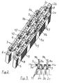
- FIG. 1 shows an exemplary embodiment of a vehicle heater 1 with a plurality of heat exchangers 2 which can be flowed through by an air flow to be heated and are arranged one behind the other in the flow direction.
- the heat exchanger 2 have heater receptacles with openings in which heaters 10, their construction in FIG. 4 is shown stuck.
- the heating devices 10 are connected to contact rails 3, which extend perpendicular to the flow direction and are connected as intended to the poles of a voltage source.
- the heat exchanger 2 with the heaters 10 attached to them are connected by a holder 4 to form an assembly.
- the holder 4 may for example be made of plastic or metal, in particular aluminum.
- the holder 4 is made of metal and can therefore be used advantageously for electrical grounding of the heat exchanger 2.
- the holder 4 is connected by clamping with the heat exchangers 2.
- a positive fastening of the heat exchanger 2 to the holder 4 is possible, for example by screwing or latching.
- FIG. 2 is the in FIG. 1 shown vehicle heater shown without the bracket.
- the vehicle heater has three identical heat exchangers 2a, 2b, 2c, which are arranged one behind the other in the flow direction. Adjacent heat exchangers 2a, 2b, 2c are arranged offset transversely to the flow direction. It is advantageous in this way that the heating devices 10 of adjacent heat exchangers 2a, 2b, 2c are arranged offset in relation to the flow direction and therefore results in an improved heat transfer to the air flow.
- the heat exchangers 2a, 2b, 2c are in the illustrated embodiment extruded profiles having openings 5, which can be traversed by an air flow transverse to the extrusion direction. These openings 5 are shown only schematically by strip-shaped areas of the extruded profile in the illustrated embodiment. In the strip-shaped areas a plurality of openings 5 is arranged. The apertures 5 can be punched, for example, in the extruded profile and formed almost arbitrarily. In particular, circular or slot-shaped holes are suitable.
- the extruded profiles 2a, 2b, 2c each have a plurality, in the illustrated embodiment, four tubes 6, in which the heating devices 10 stuck.
- the Tubes 6 and the openings of these rectangular tubes 6 thus form receptacles for the heaters 10.
- the extruded profiles 2 a, 2 b, 2 c have heat release ribs 7, which emanate from a base plate 8, in which the openings 5 through which the heating air flow can flow. In the illustrated embodiment, only from one side of this plate 8 heat release ribs 7 go out. However, it can emanate from both sides of the plate 8 heat release ribs 7.
- FIG. 3 shows a detail of a side view FIG. 2 with viewing direction perpendicular to the flow direction and perpendicular to the extrusion direction of the heat exchanger 2a, 2b, 2c.
- the already mentioned contact rails 3 are in the FIGS. 1 and 2 to recognize more clearly.
- heaters 10 of two adjacent heat exchangers 2a, 2b, 2c are connected to each contact rail.
- electrical connections 9a, 9b are attached.
- the terminals 9a are connected as intended to the negative terminal and the terminals 9b to the positive terminal of a voltage source. In this way it follows that the heating means 10 of adjacent heat exchangers 2a, 2b, 2c are each traversed by electricity in the reverse direction.
- Each of the heating devices 10 has two identical contact plates 11 between which a plurality of block-shaped heating elements 12 of a PTC ceramic (p ositiver T emperature ostory c) are arranged.
- the contact plates 11 each carry a positioning frame 13 which defines receptacles 14 for the heating elements 12.
- the positioning frame 13 is preferably made of plastic and may be pushed onto the contact plates 11. However, the positioning frame 13 can also be molded around the contact plates 11 around.
- the positioning frame 13 has clamping lugs 18, which are arranged on the receptacles 14 surrounding inner sides and fix the inserted heating elements by clamping.
- the contact plates 11, positioning frame 13 and the heating elements 12 can be pre-assembled into a unit that can be handled well.
- the positioning frame 13 leaves in the illustrated embodiment, facing away from the heating elements 12 back of the contact plates 11 free.
- the contact plates 11 carry on their side facing away from the heating elements 12 side an electrically insulating support 15, in the illustrated embodiment, a strip of Kapton or ceramic.
- the insulation can also be formed by the positioning frame 13 or by wrapping with plastic film, such as Kapton film.
- a support 15 is used and wrapped as additional insulation with foil.
- the components of a preassembled heating device 10 can be held together by a film, so that they can be handled better.
- ends 11a of the contact plates 11 are bent. These ends 11a can be fixed to the contact rails 3, for example, by rivets 3a or screws. In a corresponding manner, the bent ends 11a of the contact plates are also fastened to the contact rails 3 by rivets 3a.
- FIGS. 5 and 6 show the holder 4 with a view of the bottom, which faces the heat exchangers 2a, 2b, 2c in the assembled state.
- FIG. 5 is the holder 4 without heat exchanger 2a, 2b, 2c
- FIG. 6 shown with heat exchanger 2a, 2b, 2c.
- the holder 4 is connected by clamping with the heat exchangers 2a, 2b, 2c.
- the holder has 4 positioning and clamping elements 16, 17, between which the heat exchangers 2a, 2b, 2c are clamped.
- the positioning and clamping elements 16, 17 are arranged in several rows on the underside of the holder 4. These rows are transverse to the flow direction and are arranged offset to one another.
- a heat exchanger 2a, 2b, 2c is thus clamped between two rows of positioning and clamping elements 16, 17.
- An element 16, 17 of the one row is a gap hiss elements 16, 17 of the other row opposite.
- the clamping elements 16 engage between the heat discharge ribs 7.
- the clamping elements 16 are formed in the illustrated embodiment, approximately as rectangular pins or ribs, which are clamped between adjacent heat-dissipating ribs 7. At the same time serve the clamping elements 16 as a stop for the adjacent heat exchanger 2a, or 2b.
- the elements 17 may also have a clamping function or merely serve as stops for positioning the heat exchangers 2a, 2b, 2c.
Landscapes
- Engineering & Computer Science (AREA)
- Physics & Mathematics (AREA)
- Thermal Sciences (AREA)
- Mechanical Engineering (AREA)
- Chemical & Material Sciences (AREA)
- Combustion & Propulsion (AREA)
- General Engineering & Computer Science (AREA)
- Air-Conditioning For Vehicles (AREA)
- Heat-Exchange Devices With Radiators And Conduit Assemblies (AREA)
- Resistance Heating (AREA)
Applications Claiming Priority (1)
| Application Number | Priority Date | Filing Date | Title |
|---|---|---|---|
| DE102008033142A DE102008033142A1 (de) | 2008-07-15 | 2008-07-15 | Fahrzeugheizung |
Publications (3)
| Publication Number | Publication Date |
|---|---|
| EP2145783A2 true EP2145783A2 (fr) | 2010-01-20 |
| EP2145783A3 EP2145783A3 (fr) | 2010-05-05 |
| EP2145783B1 EP2145783B1 (fr) | 2011-09-07 |
Family
ID=40984781
Family Applications (1)
| Application Number | Title | Priority Date | Filing Date |
|---|---|---|---|
| EP09009245A Active EP2145783B1 (fr) | 2008-07-15 | 2009-07-15 | Chauffage de véhicule |
Country Status (4)
| Country | Link |
|---|---|
| US (1) | US9827828B2 (fr) |
| EP (1) | EP2145783B1 (fr) |
| AT (1) | ATE523363T1 (fr) |
| DE (1) | DE102008033142A1 (fr) |
Cited By (1)
| Publication number | Priority date | Publication date | Assignee | Title |
|---|---|---|---|---|
| EP2797382A1 (fr) * | 2013-04-26 | 2014-10-29 | Eberspächer catem GmbH & Co. KG | Chauffe-eau et système de chauffage pour un véhicule électrique avec chauffe-eau |
Families Citing this family (6)
| Publication number | Priority date | Publication date | Assignee | Title |
|---|---|---|---|---|
| KR101218877B1 (ko) * | 2010-09-01 | 2013-01-07 | 갑을오토텍(주) | 고전압 고전류용 피티씨 로드 조립체가 구비된 히터 |
| DE102013106060B4 (de) * | 2013-06-11 | 2016-08-18 | Jui-Chien Kao | Positionierrahmen for buchseneinsätze |
| DE102013114471A1 (de) * | 2013-10-31 | 2015-04-30 | Borgwarner Ludwigsburg Gmbh | Heizvorrichtung |
| KR101961290B1 (ko) * | 2013-12-31 | 2019-03-25 | 한온시스템 주식회사 | Ptc 히터 |
| EP3141842B1 (fr) | 2015-09-11 | 2019-11-06 | Mahle International GmbH | Chauffage ptc pour un système de conditionnement d'air, en particulier d'un véhicule automobile |
| KR101913121B1 (ko) * | 2016-01-28 | 2018-10-31 | 자화전자(주) | 독립제어 피티씨히터 및 장치 |
Citations (1)
| Publication number | Priority date | Publication date | Assignee | Title |
|---|---|---|---|---|
| EP1768457A1 (fr) | 2005-09-23 | 2007-03-28 | Catem GmbH & Co.KG | Element chauffant d'un dispositif de chauffage |
Family Cites Families (23)
| Publication number | Priority date | Publication date | Assignee | Title |
|---|---|---|---|---|
| GB8411591D0 (en) | 1984-05-05 | 1984-06-13 | Davison G W | Pipe-laying apparatus |
| US4939349A (en) * | 1989-06-23 | 1990-07-03 | Uppermost Electronic Industries Co., Ltd. | Ceramic thermistor heating element |
| US5239163A (en) | 1991-06-19 | 1993-08-24 | Texas Instruments Incorporated | Automobile air heater utilizing PTC tablets adhesively fixed to tubular heat sinks |
| FR2701757B1 (fr) | 1993-02-18 | 1995-04-21 | Valeo Thermique Habitacle | Radiateur de chauffage électrique, notamment pour l'habitacle d'un véhicule automobile. |
| US5471034A (en) * | 1993-03-17 | 1995-11-28 | Texas Instruments Incorporated | Heater apparatus and process for heating a fluid stream with PTC heating elements electrically connected in series |
| DE19706199B4 (de) | 1997-02-18 | 2005-11-10 | Behr Gmbh & Co. Kg | Elektrische Heizeinrichtung, insbesondere für ein Kraftfahrzeug |
| DE19846169A1 (de) | 1998-10-07 | 2000-04-13 | Alcatel Sa | Verfahren zur Signalisierung verkehrsrelevanter Zustandsinformationen |
| US6180930B1 (en) * | 1999-12-29 | 2001-01-30 | Chia-Hsiung Wu | Heater with enclosing envelope |
| EP1429084A1 (fr) | 2002-12-10 | 2004-06-16 | Behr France S.A.R.L. | Radiateur avec élément chauffant électrique supplémentaire |
| EP1432287B1 (fr) | 2002-12-19 | 2006-06-21 | Catem GmbH & Co.KG | Dispositif de chauffage électrique avec boîtier |
| ATE295281T1 (de) | 2003-02-28 | 2005-05-15 | Catem Gmbh & Co Kg | Elektrische heizvorrichtung mit heizzonen |
| FR2855933B1 (fr) * | 2003-06-06 | 2006-06-09 | Valeo Climatisation | Dispositif de chauffage electrique, notamment pour un vehicule automobile |
| EP1503153B1 (fr) | 2003-07-31 | 2011-03-30 | Behr France Rouffach SAS | Dispositif d'échange de chaleur |
| EP1515587B1 (fr) * | 2003-09-11 | 2006-12-13 | Catem GmbH & Co. KG | Dispositif de chauffage électrique muni d'un élément chauffant scellé |
| KR100445723B1 (ko) * | 2003-11-18 | 2004-08-26 | 우리산업 주식회사 | Ptc 소자 모듈 및 이를 포함하는 차량용 프리히터 |
| ATE340977T1 (de) * | 2004-03-09 | 2006-10-15 | Cebi Spa | Elektrische heizvorrichtung für kraftfahrzeugventilationsanordnung |
| JP4006711B2 (ja) | 2004-03-22 | 2007-11-14 | 漢拏空調株式会社 | 電熱ヒーター |
| SI21932A (sl) | 2004-12-02 | 2006-06-30 | Aet Druzba Za Proizvodnjo Vzignih Sistemov In Elektronike D.O.O. | Elektricni grelnik zraka |
| DE502005005348D1 (de) | 2005-10-26 | 2008-10-23 | Behr France Rouffach Sas | Heizungsanordnung mit elektrischen Heizelementen für ein Kraftfahrzeug |
| DE102006018784B4 (de) * | 2005-12-20 | 2007-12-20 | Beru Ag | Elektrische Heizvorrichtung, insbesondere für Automobile |
| WO2007071335A1 (fr) | 2005-12-20 | 2007-06-28 | Beru Aktiengesellschaft | Systeme de chauffage electrique, notamment pour automobiles |
| ES2376387T3 (es) | 2006-06-28 | 2012-03-13 | Eberspächer Catem Gmbh & Co. Kg | Dispositivo calefactor eléctrico. |
| US7576305B2 (en) | 2006-09-22 | 2009-08-18 | Catem Gmbh & Co. Kg | Heat-generating element of a heating device |
-
2008
- 2008-07-15 DE DE102008033142A patent/DE102008033142A1/de not_active Withdrawn
-
2009
- 2009-07-10 US US12/459,955 patent/US9827828B2/en active Active
- 2009-07-15 AT AT09009245T patent/ATE523363T1/de active
- 2009-07-15 EP EP09009245A patent/EP2145783B1/fr active Active
Patent Citations (1)
| Publication number | Priority date | Publication date | Assignee | Title |
|---|---|---|---|---|
| EP1768457A1 (fr) | 2005-09-23 | 2007-03-28 | Catem GmbH & Co.KG | Element chauffant d'un dispositif de chauffage |
Cited By (1)
| Publication number | Priority date | Publication date | Assignee | Title |
|---|---|---|---|---|
| EP2797382A1 (fr) * | 2013-04-26 | 2014-10-29 | Eberspächer catem GmbH & Co. KG | Chauffe-eau et système de chauffage pour un véhicule électrique avec chauffe-eau |
Also Published As
| Publication number | Publication date |
|---|---|
| EP2145783A3 (fr) | 2010-05-05 |
| DE102008033142A1 (de) | 2010-01-21 |
| EP2145783B1 (fr) | 2011-09-07 |
| US9827828B2 (en) | 2017-11-28 |
| US20100012640A1 (en) | 2010-01-21 |
| ATE523363T1 (de) | 2011-09-15 |
Similar Documents
| Publication | Publication Date | Title |
|---|---|---|
| EP2145783B1 (fr) | Chauffage de véhicule | |
| EP2608632B1 (fr) | Dispositif de chauffage électrique et cadre associé | |
| EP1318694B1 (fr) | Dispositif de chauffage électrique | |
| EP1963753B1 (fr) | Systeme de chauffage electrique, notamment pour automobiles | |
| DE102006018784B4 (de) | Elektrische Heizvorrichtung, insbesondere für Automobile | |
| EP3273177B1 (fr) | Dispositif de chauffage électrique | |
| DE102006055216B4 (de) | Heizeinrichtung für Dieselkraftstoff und beheizbares Dieselfiltersystem | |
| EP2137468A1 (fr) | Appareil de chauffage électrique, notamment pour une automobile | |
| EP2608631A1 (fr) | Elément générateur de chaleur | |
| WO2006012963A1 (fr) | Dispositif de chauffage comportant un element chauffant, destine notamment a un vehicule a moteur | |
| EP2607808A1 (fr) | Elément générateur de chaleur | |
| EP2145782B1 (fr) | Chauffage de véhicule | |
| DE19706199A1 (de) | Elektrische Heizeinrichtung, insbesondere für ein Kraftfahrzeug | |
| WO2016005205A1 (fr) | Dispositif de commande pour dispositif de chauffage électrique et procédé pour sa production | |
| WO2004080738A1 (fr) | Dispositif de chauffage electrique, utilise en particulier pour des vehicules | |
| EP1522439B1 (fr) | Dispositif de chauffage avec élément à coefficient positif, en particulier pour un véhicule automobile | |
| EP2282605A1 (fr) | Dispositif de chauffage | |
| DE102015120183A1 (de) | Radiatoranordnung für einen elektrischen Heizer und elektrischer Heizer | |
| DE102009033988A1 (de) | Heizvorrichtung | |
| EP1457368B1 (fr) | Echangeur de chaleur avec chauffage électrique supplémentaire intégré | |
| EP3557155B1 (fr) | Dispositif de chauffage électrique | |
| DE102012112837A1 (de) | Fahrzeugheizung und Verfahren zum Herstellen einer Fahrzeugheizung | |
| DE102008033143B4 (de) | Heizvorrichtung | |
| DE102009033987B4 (de) | Heizvorrichtung | |
| DE19712178C2 (de) | Elektrische Heizeinrichtung, insbesondere für ein Kraftfahrzeug |
Legal Events
| Date | Code | Title | Description |
|---|---|---|---|
| PUAI | Public reference made under article 153(3) epc to a published international application that has entered the european phase |
Free format text: ORIGINAL CODE: 0009012 |
|
| AK | Designated contracting states |
Kind code of ref document: A2 Designated state(s): AT BE BG CH CY CZ DE DK EE ES FI FR GB GR HR HU IE IS IT LI LT LU LV MC MK MT NL NO PL PT RO SE SI SK SM TR |
|
| AX | Request for extension of the european patent |
Extension state: AL BA RS |
|
| PUAL | Search report despatched |
Free format text: ORIGINAL CODE: 0009013 |
|
| AK | Designated contracting states |
Kind code of ref document: A3 Designated state(s): AT BE BG CH CY CZ DE DK EE ES FI FR GB GR HR HU IE IS IT LI LT LU LV MC MK MT NL NO PL PT RO SE SI SK SM TR |
|
| AX | Request for extension of the european patent |
Extension state: AL BA RS |
|
| RAP1 | Party data changed (applicant data changed or rights of an application transferred) |
Owner name: BORGWARNER BERU SYSTEMS GMBH Owner name: EICHENAUER HEIZELEMENTE GMBH & CO. KG |
|
| 17P | Request for examination filed |
Effective date: 20100624 |
|
| RAP1 | Party data changed (applicant data changed or rights of an application transferred) |
Owner name: BORGWARNER BERU SYSTEMS GMBH |
|
| RIC1 | Information provided on ipc code assigned before grant |
Ipc: B60H 1/00 20060101AFI20110401BHEP |
|
| GRAP | Despatch of communication of intention to grant a patent |
Free format text: ORIGINAL CODE: EPIDOSNIGR1 |
|
| GRAS | Grant fee paid |
Free format text: ORIGINAL CODE: EPIDOSNIGR3 |
|
| GRAA | (expected) grant |
Free format text: ORIGINAL CODE: 0009210 |
|
| REG | Reference to a national code |
Ref country code: GB Ref legal event code: FG4D Free format text: NOT ENGLISH |
|
| REG | Reference to a national code |
Ref country code: CH Ref legal event code: EP |
|
| REG | Reference to a national code |
Ref country code: IE Ref legal event code: FG4D Free format text: LANGUAGE OF EP DOCUMENT: GERMAN |
|
| REG | Reference to a national code |
Ref country code: DE Ref legal event code: R096 Ref document number: 502009001282 Country of ref document: DE Effective date: 20111110 |
|
| REG | Reference to a national code |
Ref country code: NL Ref legal event code: VDEP Effective date: 20110907 |
|
| PG25 | Lapsed in a contracting state [announced via postgrant information from national office to epo] |
Ref country code: FI Free format text: LAPSE BECAUSE OF FAILURE TO SUBMIT A TRANSLATION OF THE DESCRIPTION OR TO PAY THE FEE WITHIN THE PRESCRIBED TIME-LIMIT Effective date: 20110907 Ref country code: NO Free format text: LAPSE BECAUSE OF FAILURE TO SUBMIT A TRANSLATION OF THE DESCRIPTION OR TO PAY THE FEE WITHIN THE PRESCRIBED TIME-LIMIT Effective date: 20111207 Ref country code: HR Free format text: LAPSE BECAUSE OF FAILURE TO SUBMIT A TRANSLATION OF THE DESCRIPTION OR TO PAY THE FEE WITHIN THE PRESCRIBED TIME-LIMIT Effective date: 20110907 Ref country code: LT Free format text: LAPSE BECAUSE OF FAILURE TO SUBMIT A TRANSLATION OF THE DESCRIPTION OR TO PAY THE FEE WITHIN THE PRESCRIBED TIME-LIMIT Effective date: 20110907 Ref country code: SE Free format text: LAPSE BECAUSE OF FAILURE TO SUBMIT A TRANSLATION OF THE DESCRIPTION OR TO PAY THE FEE WITHIN THE PRESCRIBED TIME-LIMIT Effective date: 20110907 |
|
| LTIE | Lt: invalidation of european patent or patent extension |
Effective date: 20110907 |
|
| PG25 | Lapsed in a contracting state [announced via postgrant information from national office to epo] |
Ref country code: LV Free format text: LAPSE BECAUSE OF FAILURE TO SUBMIT A TRANSLATION OF THE DESCRIPTION OR TO PAY THE FEE WITHIN THE PRESCRIBED TIME-LIMIT Effective date: 20110907 Ref country code: CY Free format text: LAPSE BECAUSE OF FAILURE TO SUBMIT A TRANSLATION OF THE DESCRIPTION OR TO PAY THE FEE WITHIN THE PRESCRIBED TIME-LIMIT Effective date: 20110907 Ref country code: SI Free format text: LAPSE BECAUSE OF FAILURE TO SUBMIT A TRANSLATION OF THE DESCRIPTION OR TO PAY THE FEE WITHIN THE PRESCRIBED TIME-LIMIT Effective date: 20110907 Ref country code: GR Free format text: LAPSE BECAUSE OF FAILURE TO SUBMIT A TRANSLATION OF THE DESCRIPTION OR TO PAY THE FEE WITHIN THE PRESCRIBED TIME-LIMIT Effective date: 20111208 |
|
| REG | Reference to a national code |
Ref country code: IE Ref legal event code: FD4D |
|
| PG25 | Lapsed in a contracting state [announced via postgrant information from national office to epo] |
Ref country code: IE Free format text: LAPSE BECAUSE OF FAILURE TO SUBMIT A TRANSLATION OF THE DESCRIPTION OR TO PAY THE FEE WITHIN THE PRESCRIBED TIME-LIMIT Effective date: 20110907 Ref country code: SK Free format text: LAPSE BECAUSE OF FAILURE TO SUBMIT A TRANSLATION OF THE DESCRIPTION OR TO PAY THE FEE WITHIN THE PRESCRIBED TIME-LIMIT Effective date: 20110907 Ref country code: IS Free format text: LAPSE BECAUSE OF FAILURE TO SUBMIT A TRANSLATION OF THE DESCRIPTION OR TO PAY THE FEE WITHIN THE PRESCRIBED TIME-LIMIT Effective date: 20120107 Ref country code: CZ Free format text: LAPSE BECAUSE OF FAILURE TO SUBMIT A TRANSLATION OF THE DESCRIPTION OR TO PAY THE FEE WITHIN THE PRESCRIBED TIME-LIMIT Effective date: 20110907 |
|
| PG25 | Lapsed in a contracting state [announced via postgrant information from national office to epo] |
Ref country code: NL Free format text: LAPSE BECAUSE OF FAILURE TO SUBMIT A TRANSLATION OF THE DESCRIPTION OR TO PAY THE FEE WITHIN THE PRESCRIBED TIME-LIMIT Effective date: 20110907 Ref country code: PT Free format text: LAPSE BECAUSE OF FAILURE TO SUBMIT A TRANSLATION OF THE DESCRIPTION OR TO PAY THE FEE WITHIN THE PRESCRIBED TIME-LIMIT Effective date: 20120109 Ref country code: EE Free format text: LAPSE BECAUSE OF FAILURE TO SUBMIT A TRANSLATION OF THE DESCRIPTION OR TO PAY THE FEE WITHIN THE PRESCRIBED TIME-LIMIT Effective date: 20110907 Ref country code: PL Free format text: LAPSE BECAUSE OF FAILURE TO SUBMIT A TRANSLATION OF THE DESCRIPTION OR TO PAY THE FEE WITHIN THE PRESCRIBED TIME-LIMIT Effective date: 20110907 Ref country code: IT Free format text: LAPSE BECAUSE OF FAILURE TO SUBMIT A TRANSLATION OF THE DESCRIPTION OR TO PAY THE FEE WITHIN THE PRESCRIBED TIME-LIMIT Effective date: 20110907 Ref country code: RO Free format text: LAPSE BECAUSE OF FAILURE TO SUBMIT A TRANSLATION OF THE DESCRIPTION OR TO PAY THE FEE WITHIN THE PRESCRIBED TIME-LIMIT Effective date: 20110907 |
|
| PLBE | No opposition filed within time limit |
Free format text: ORIGINAL CODE: 0009261 |
|
| STAA | Information on the status of an ep patent application or granted ep patent |
Free format text: STATUS: NO OPPOSITION FILED WITHIN TIME LIMIT |
|
| PG25 | Lapsed in a contracting state [announced via postgrant information from national office to epo] |
Ref country code: DK Free format text: LAPSE BECAUSE OF FAILURE TO SUBMIT A TRANSLATION OF THE DESCRIPTION OR TO PAY THE FEE WITHIN THE PRESCRIBED TIME-LIMIT Effective date: 20110907 |
|
| 26N | No opposition filed |
Effective date: 20120611 |
|
| REG | Reference to a national code |
Ref country code: DE Ref legal event code: R097 Ref document number: 502009001282 Country of ref document: DE Effective date: 20120611 |
|
| BERE | Be: lapsed |
Owner name: BORGWARNER BERU SYSTEMS G.M.B.H. Effective date: 20120731 |
|
| PG25 | Lapsed in a contracting state [announced via postgrant information from national office to epo] |
Ref country code: MK Free format text: LAPSE BECAUSE OF FAILURE TO SUBMIT A TRANSLATION OF THE DESCRIPTION OR TO PAY THE FEE WITHIN THE PRESCRIBED TIME-LIMIT Effective date: 20110907 Ref country code: MC Free format text: LAPSE BECAUSE OF NON-PAYMENT OF DUE FEES Effective date: 20120731 |
|
| REG | Reference to a national code |
Ref country code: FR Ref legal event code: ST Effective date: 20130329 |
|
| PG25 | Lapsed in a contracting state [announced via postgrant information from national office to epo] |
Ref country code: ES Free format text: LAPSE BECAUSE OF FAILURE TO SUBMIT A TRANSLATION OF THE DESCRIPTION OR TO PAY THE FEE WITHIN THE PRESCRIBED TIME-LIMIT Effective date: 20111218 Ref country code: FR Free format text: LAPSE BECAUSE OF NON-PAYMENT OF DUE FEES Effective date: 20120731 |
|
| PG25 | Lapsed in a contracting state [announced via postgrant information from national office to epo] |
Ref country code: BE Free format text: LAPSE BECAUSE OF NON-PAYMENT OF DUE FEES Effective date: 20120731 |
|
| PG25 | Lapsed in a contracting state [announced via postgrant information from national office to epo] |
Ref country code: BG Free format text: LAPSE BECAUSE OF FAILURE TO SUBMIT A TRANSLATION OF THE DESCRIPTION OR TO PAY THE FEE WITHIN THE PRESCRIBED TIME-LIMIT Effective date: 20111207 |
|
| PG25 | Lapsed in a contracting state [announced via postgrant information from national office to epo] |
Ref country code: MT Free format text: LAPSE BECAUSE OF FAILURE TO SUBMIT A TRANSLATION OF THE DESCRIPTION OR TO PAY THE FEE WITHIN THE PRESCRIBED TIME-LIMIT Effective date: 20110907 |
|
| REG | Reference to a national code |
Ref country code: CH Ref legal event code: PL |
|
| GBPC | Gb: european patent ceased through non-payment of renewal fee |
Effective date: 20130715 |
|
| PG25 | Lapsed in a contracting state [announced via postgrant information from national office to epo] |
Ref country code: LI Free format text: LAPSE BECAUSE OF NON-PAYMENT OF DUE FEES Effective date: 20130731 Ref country code: TR Free format text: LAPSE BECAUSE OF FAILURE TO SUBMIT A TRANSLATION OF THE DESCRIPTION OR TO PAY THE FEE WITHIN THE PRESCRIBED TIME-LIMIT Effective date: 20110907 Ref country code: GB Free format text: LAPSE BECAUSE OF NON-PAYMENT OF DUE FEES Effective date: 20130715 Ref country code: CH Free format text: LAPSE BECAUSE OF NON-PAYMENT OF DUE FEES Effective date: 20130731 |
|
| PG25 | Lapsed in a contracting state [announced via postgrant information from national office to epo] |
Ref country code: LU Free format text: LAPSE BECAUSE OF NON-PAYMENT OF DUE FEES Effective date: 20120715 Ref country code: SM Free format text: LAPSE BECAUSE OF FAILURE TO SUBMIT A TRANSLATION OF THE DESCRIPTION OR TO PAY THE FEE WITHIN THE PRESCRIBED TIME-LIMIT Effective date: 20110907 |
|
| PG25 | Lapsed in a contracting state [announced via postgrant information from national office to epo] |
Ref country code: HU Free format text: LAPSE BECAUSE OF FAILURE TO SUBMIT A TRANSLATION OF THE DESCRIPTION OR TO PAY THE FEE WITHIN THE PRESCRIBED TIME-LIMIT Effective date: 20090715 |
|
| REG | Reference to a national code |
Ref country code: DE Ref legal event code: R082 Ref document number: 502009001282 Country of ref document: DE Representative=s name: TWELMEIER MOMMER & PARTNER PATENT- UND RECHTSA, DE |
|
| REG | Reference to a national code |
Ref country code: DE Ref legal event code: R082 Ref document number: 502009001282 Country of ref document: DE Representative=s name: TWELMEIER MOMMER & PARTNER PATENT- UND RECHTSA, DE Effective date: 20150225 Ref country code: DE Ref legal event code: R081 Ref document number: 502009001282 Country of ref document: DE Owner name: BORGWARNER LUDWIGSBURG GMBH, DE Free format text: FORMER OWNER: BORGWARNER BERU SYSTEMS GMBH, 71636 LUDWIGSBURG, DE Effective date: 20150225 |
|
| REG | Reference to a national code |
Ref country code: AT Ref legal event code: MM01 Ref document number: 523363 Country of ref document: AT Kind code of ref document: T Effective date: 20140715 |
|
| PG25 | Lapsed in a contracting state [announced via postgrant information from national office to epo] |
Ref country code: AT Free format text: LAPSE BECAUSE OF NON-PAYMENT OF DUE FEES Effective date: 20140715 |
|
| P01 | Opt-out of the competence of the unified patent court (upc) registered |
Effective date: 20230327 |
|
| PGFP | Annual fee paid to national office [announced via postgrant information from national office to epo] |
Ref country code: DE Payment date: 20230912 Year of fee payment: 15 |