EP2592982B1 - Dispositif de chauffe instantané dynamique - Google Patents
Dispositif de chauffe instantané dynamique Download PDFInfo
- Publication number
- EP2592982B1 EP2592982B1 EP11732379.0A EP11732379A EP2592982B1 EP 2592982 B1 EP2592982 B1 EP 2592982B1 EP 11732379 A EP11732379 A EP 11732379A EP 2592982 B1 EP2592982 B1 EP 2592982B1
- Authority
- EP
- European Patent Office
- Prior art keywords
- fluid
- heater
- section
- connection
- metal tube
- Prior art date
- Legal status (The legal status is an assumption and is not a legal conclusion. Google has not performed a legal analysis and makes no representation as to the accuracy of the status listed.)
- Active
Links
- 239000012530 fluid Substances 0.000 claims description 680
- 229910052751 metal Inorganic materials 0.000 claims description 159
- 239000002184 metal Substances 0.000 claims description 159
- 238000010438 heat treatment Methods 0.000 claims description 47
- 239000004033 plastic Substances 0.000 claims description 26
- 229920003023 plastic Polymers 0.000 claims description 26
- 239000010935 stainless steel Substances 0.000 claims description 18
- 229910001220 stainless steel Inorganic materials 0.000 claims description 18
- 230000007704 transition Effects 0.000 claims description 17
- 229920001971 elastomer Polymers 0.000 claims description 6
- 239000000806 elastomer Substances 0.000 claims description 5
- 229910000831 Steel Inorganic materials 0.000 claims description 3
- 239000010959 steel Substances 0.000 claims description 3
- 238000007789 sealing Methods 0.000 description 21
- 230000002829 reductive effect Effects 0.000 description 12
- 238000011161 development Methods 0.000 description 11
- 230000018109 developmental process Effects 0.000 description 11
- 239000000463 material Substances 0.000 description 11
- 235000008733 Citrus aurantifolia Nutrition 0.000 description 10
- 235000011941 Tilia x europaea Nutrition 0.000 description 10
- 230000008901 benefit Effects 0.000 description 10
- 239000004571 lime Substances 0.000 description 10
- 238000004519 manufacturing process Methods 0.000 description 8
- 230000000712 assembly Effects 0.000 description 7
- 238000000429 assembly Methods 0.000 description 7
- 238000013461 design Methods 0.000 description 7
- 230000036961 partial effect Effects 0.000 description 7
- 230000006870 function Effects 0.000 description 6
- 125000006850 spacer group Chemical group 0.000 description 6
- 238000012546 transfer Methods 0.000 description 6
- 229910052782 aluminium Inorganic materials 0.000 description 5
- XAGFODPZIPBFFR-UHFFFAOYSA-N aluminium Chemical compound [Al] XAGFODPZIPBFFR-UHFFFAOYSA-N 0.000 description 5
- 230000008859 change Effects 0.000 description 5
- 235000013353 coffee beverage Nutrition 0.000 description 5
- 239000004020 conductor Substances 0.000 description 5
- 230000007423 decrease Effects 0.000 description 5
- 239000011295 pitch Substances 0.000 description 5
- 238000005476 soldering Methods 0.000 description 5
- 239000004954 Polyphthalamide Substances 0.000 description 4
- 230000013011 mating Effects 0.000 description 4
- 238000013021 overheating Methods 0.000 description 4
- 230000002093 peripheral effect Effects 0.000 description 4
- 229920006375 polyphtalamide Polymers 0.000 description 4
- 239000000565 sealant Substances 0.000 description 4
- 229920002725 thermoplastic elastomer Polymers 0.000 description 4
- RYGMFSIKBFXOCR-UHFFFAOYSA-N Copper Chemical compound [Cu] RYGMFSIKBFXOCR-UHFFFAOYSA-N 0.000 description 3
- 239000004697 Polyetherimide Substances 0.000 description 3
- 230000002308 calcification Effects 0.000 description 3
- 229910052802 copper Inorganic materials 0.000 description 3
- 239000010949 copper Substances 0.000 description 3
- 238000002788 crimping Methods 0.000 description 3
- 238000009826 distribution Methods 0.000 description 3
- 238000005516 engineering process Methods 0.000 description 3
- 230000002349 favourable effect Effects 0.000 description 3
- 230000004907 flux Effects 0.000 description 3
- 238000009434 installation Methods 0.000 description 3
- 229920001601 polyetherimide Polymers 0.000 description 3
- 229920001296 polysiloxane Polymers 0.000 description 3
- 229910000679 solder Inorganic materials 0.000 description 3
- KAKZBPTYRLMSJV-UHFFFAOYSA-N Butadiene Chemical compound C=CC=C KAKZBPTYRLMSJV-UHFFFAOYSA-N 0.000 description 2
- 229920002943 EPDM rubber Polymers 0.000 description 2
- 229920000181 Ethylene propylene rubber Polymers 0.000 description 2
- 229920006169 Perfluoroelastomer Polymers 0.000 description 2
- UCKMPCXJQFINFW-UHFFFAOYSA-N Sulphide Chemical compound [S-2] UCKMPCXJQFINFW-UHFFFAOYSA-N 0.000 description 2
- 229910045601 alloy Inorganic materials 0.000 description 2
- 239000000956 alloy Substances 0.000 description 2
- 238000006243 chemical reaction Methods 0.000 description 2
- 238000004891 communication Methods 0.000 description 2
- 230000000295 complement effect Effects 0.000 description 2
- 230000008021 deposition Effects 0.000 description 2
- 229920001973 fluoroelastomer Polymers 0.000 description 2
- NBVXSUQYWXRMNV-UHFFFAOYSA-N fluoromethane Chemical compound FC NBVXSUQYWXRMNV-UHFFFAOYSA-N 0.000 description 2
- 235000013305 food Nutrition 0.000 description 2
- 238000009413 insulation Methods 0.000 description 2
- 230000003993 interaction Effects 0.000 description 2
- 239000007788 liquid Substances 0.000 description 2
- 238000000034 method Methods 0.000 description 2
- 229920006389 polyphenyl polymer Polymers 0.000 description 2
- 230000008569 process Effects 0.000 description 2
- 230000009467 reduction Effects 0.000 description 2
- XLYOFNOQVPJJNP-UHFFFAOYSA-N water Substances O XLYOFNOQVPJJNP-UHFFFAOYSA-N 0.000 description 2
- 241000219470 Mirabilis Species 0.000 description 1
- 229910000639 Spring steel Inorganic materials 0.000 description 1
- 230000001133 acceleration Effects 0.000 description 1
- 230000009471 action Effects 0.000 description 1
- 230000006978 adaptation Effects 0.000 description 1
- 230000004323 axial length Effects 0.000 description 1
- 239000011324 bead Substances 0.000 description 1
- 239000000919 ceramic Substances 0.000 description 1
- 239000004927 clay Substances 0.000 description 1
- 150000001875 compounds Chemical class 0.000 description 1
- 238000010276 construction Methods 0.000 description 1
- 238000005520 cutting process Methods 0.000 description 1
- 230000003247 decreasing effect Effects 0.000 description 1
- 230000001066 destructive effect Effects 0.000 description 1
- 238000001514 detection method Methods 0.000 description 1
- 230000000694 effects Effects 0.000 description 1
- 238000005485 electric heating Methods 0.000 description 1
- 235000015114 espresso Nutrition 0.000 description 1
- 235000012171 hot beverage Nutrition 0.000 description 1
- 230000006872 improvement Effects 0.000 description 1
- 238000001746 injection moulding Methods 0.000 description 1
- 230000010354 integration Effects 0.000 description 1
- 235000000396 iron Nutrition 0.000 description 1
- 238000002386 leaching Methods 0.000 description 1
- CPLXHLVBOLITMK-UHFFFAOYSA-N magnesium oxide Inorganic materials [Mg]=O CPLXHLVBOLITMK-UHFFFAOYSA-N 0.000 description 1
- 239000000395 magnesium oxide Substances 0.000 description 1
- AXZKOIWUVFPNLO-UHFFFAOYSA-N magnesium;oxygen(2-) Chemical compound [O-2].[Mg+2] AXZKOIWUVFPNLO-UHFFFAOYSA-N 0.000 description 1
- 238000007726 management method Methods 0.000 description 1
- 229910001092 metal group alloy Inorganic materials 0.000 description 1
- 150000002739 metals Chemical class 0.000 description 1
- 238000005555 metalworking Methods 0.000 description 1
- 239000008267 milk Substances 0.000 description 1
- 210000004080 milk Anatomy 0.000 description 1
- 235000013336 milk Nutrition 0.000 description 1
- 150000002825 nitriles Chemical class 0.000 description 1
- 239000002245 particle Substances 0.000 description 1
- 238000002360 preparation method Methods 0.000 description 1
- 238000003825 pressing Methods 0.000 description 1
- 230000002265 prevention Effects 0.000 description 1
- 230000009993 protective function Effects 0.000 description 1
- 239000004575 stone Substances 0.000 description 1
- 210000002105 tongue Anatomy 0.000 description 1
- 230000003313 weakening effect Effects 0.000 description 1
- 238000003466 welding Methods 0.000 description 1
Images


Classifications
-
- F—MECHANICAL ENGINEERING; LIGHTING; HEATING; WEAPONS; BLASTING
- F24—HEATING; RANGES; VENTILATING
- F24H—FLUID HEATERS, e.g. WATER OR AIR HEATERS, HAVING HEAT-GENERATING MEANS, e.g. HEAT PUMPS, IN GENERAL
- F24H1/00—Water heaters, e.g. boilers, continuous-flow heaters or water-storage heaters
- F24H1/10—Continuous-flow heaters, i.e. heaters in which heat is generated only while the water is flowing, e.g. with direct contact of the water with the heating medium
- F24H1/12—Continuous-flow heaters, i.e. heaters in which heat is generated only while the water is flowing, e.g. with direct contact of the water with the heating medium in which the water is kept separate from the heating medium
- F24H1/14—Continuous-flow heaters, i.e. heaters in which heat is generated only while the water is flowing, e.g. with direct contact of the water with the heating medium in which the water is kept separate from the heating medium by tubes, e.g. bent in serpentine form
- F24H1/142—Continuous-flow heaters, i.e. heaters in which heat is generated only while the water is flowing, e.g. with direct contact of the water with the heating medium in which the water is kept separate from the heating medium by tubes, e.g. bent in serpentine form using electric energy supply
-
- A—HUMAN NECESSITIES
- A47—FURNITURE; DOMESTIC ARTICLES OR APPLIANCES; COFFEE MILLS; SPICE MILLS; SUCTION CLEANERS IN GENERAL
- A47J—KITCHEN EQUIPMENT; COFFEE MILLS; SPICE MILLS; APPARATUS FOR MAKING BEVERAGES
- A47J31/00—Apparatus for making beverages
- A47J31/44—Parts or details or accessories of beverage-making apparatus
- A47J31/54—Water boiling vessels in beverage making machines
- A47J31/542—Continuous-flow heaters
Definitions
- the invention relates generally to fluid heaters, especially those of the type continuous flow heater, for household appliances.
- the invention relates to a particularly compact fluid heater with high heating power in small dimensions.
- fluid heaters In particular hot water or steam, a variety of different types and types of fluid heaters are known in the art. Domestic appliances in which fluid heaters are used are, for example, steam cleaners, steam irons, but also those for the preparation of food and / or hot drinks, such as coffee machines, espresso machines, milk frothers, steamer and others.
- the fluid guide in this case also pressures that amount to several times the atmospheric pressure to resist.
- the EP 1 321 708 shows a fluid heater for hot water or steam generation with a fluid guide and a heater, wherein the heater consists of at least two tubular heaters, which are thermally conductively connected to the liquid-conducting tube.
- the liquid-carrying tube and the tubular heater are equipped with matched contact surfaces, such that either the tubular heating elements substantially convex contact surfaces and the liquid-carrying tube have substantially corresponding concave contact surfaces or both the tubular heating elements as well the liquid-conducting tube have substantially flat contact surfaces.
- the DE 4332826 shows another fluid heater.
- a possible object of the invention can therefore be seen to improve a fluid heater in terms of its space requirement and with respect to the heat transfer and the temperature control in order to provide a particularly compact fluid heater.
- a further or alternative possible object of the invention can be seen to improve the dynamic behavior of a generic fluid heater in a control engineering view so that it has the smallest possible dead time or time constant.
- the metal tube is made of stainless steel.
- stainless steel has the clear advantage that there are no concerns about its use in the food industry.
- stainless steel has a significantly poorer heat-conducting property compared to, for example, aluminum, it is precisely this property of the fluid heater according to the invention that is advantageous, as will be made clear below.
- a fluid guide core preferably made of a plastic material is provided in the metal tube, which is designed such that the hydraulic length of the heated fluid fluid passage in the interior of the metal tube relative to the metal tube length is substantially increased.
- the fluid guide core has a helically encircling groove whose bottom and side edges, in interaction with the metal tube inner side, form a first fluid channel section for fluid guidance, through which the fluid to be heated can flow or be guided.
- the first fluid channel section formed in this way has a cross section reduced by a multiple, but its hydraulic length is significantly longer than the metal tube.
- the reduced compared to the metal tube cross-sectional area leads to a lower fluid mass to be heated per unit length.
- the helical fluid guide significantly increases the residence time of the fluid to be heated on the heated metal tube inner surface.
- the fluid heater can be significantly reduced in length by the fluid guide core according to the invention and embodiments of materials other than metal are possible for the fluid guide core, the heat capacity of the fluid heater can be significantly reduced. This makes it possible to significantly improve the dynamic behavior of the fluid heater in a control engineering viewpoint and to provide, according to the object, a flow heater with the smallest possible dead time or time constants and thus particularly favorable temperature control behavior.
- a heater As a heater are known aluminum tubular heating elements, which are preferably arranged parallel to the metal tube at this. Particularly preferably, at least two tubular heaters are provided as heating means, which face each other with respect to the metal tube to enter the heat generated electrically in the tubular heaters with low losses in the metal tube and then in the fluid, the surface of the tubular heaters is preferably concave to the surface of the Substantially cylindrical metal tube adapted.
- tubular heating element With regard to the heating device and the tubular heating element enclosed by it, it should be noted that of course more than two tubular heating elements can be provided. Although an equidistant in the circumferential direction arranging the tubular heater already offers from the aspect of efficient and uniform heat conduction, manufacturing technology or design may be an alternative arrangement advised, all of which are within the scope of the present invention.
- the heater As a heat-conducting connection between the heater, such as the tubular heaters, and the metal tube preferably a good heat conducting solder joint is used.
- the heater comprises additional heat conduction, for example, a sleeve-like, arranged around the metal tube michleitblech, in addition to already improved by the soldering heat conduction at the contact surfaces between the heater and the metal tube, the heat distribute over the whole of the heat pipe covered by the circumference of the metal tube.
- the heat-conducting medium is preferably made of a good heat-conducting material such as copper, aluminum or alloys of these metals or the like.
- the heat conducting means may comprise the entire circumference of the metal tube or, in particular, to ensure the passage of flux during the soldering process, have openings.
- the heat-conducting compensated according to the invention the poor thermal conductivity of the stainless steel tube by the heat from the at least two tubular heaters quickly distributed around the stainless steel tube and so the stainless steel tube can be heated virtually over the entire circumference.
- the metal pipe of a poorly heat conductive material such as stainless steel
- the heat conduction of a good heat conductive material such as aluminum or copper or an alloy thereof
- the heat distribution in the metal tube can be controlled by the shape of the heat conduction.
- the closure plugs to be discussed later or an end cap and fluid connection assemblies it should already be pointed out at this point that the dimensioning of the heat conduction means in the axial direction, that is to say in the axial direction. in the longitudinal direction, the metal tube has a special meaning and protective function, especially in the event of a fault.
- At least one tubular heater is designed as a high-performance tubular heater.
- high performance tubular heater is here understood any type of tubular heaters, the structure allows the conversion of high electrical power into heat.
- Such a high-performance tubular heater may have a so-called “double helix” which is embedded in an electrically insulating, highly thermally conductive material, for example compacted magnesium oxide.
- conventional tubular heaters is or are the Schuetzl 10,messer the high-performance tubular heaters in relation to the inner diameter of the jacket tube high, so that due to a reduced heat conduction between Bankdral and the outside of the jacket tube higher electrical power can be dissipated as heat.
- the clear diameter, ie the inner diameter of the tubular heater is preferably 8 mm.
- the outer diameters are preferably in the range of 10 mm to 12 mm, wherein a heating power based on the length of the heated region of the jacket tube of 25 watts / cm 2 to 30 watts / cm 2 is made possible. At the bearing surface to the metal tube or heat transfer 35 to 45 W / cm 2 are achieved.
- connection ends of the tubular heaters can be cranked away for better contacting of the surface of the metal tube and have in this connection area so-called cold ends.
- the heating coil is preferably conically shaped, wherein it changes from a larger diameter in the heating area to a smaller diameter in the connection area. This will have negative effects of the offset on the central location of the heating coil inside the tubular heater counteracted or reached a Switzerlandentiastung and avoided a local cross-sectional reduction of the helix.
- pitches i. Gradients are realized, which allow a doubling or tripling of the hydraulic length of the fluid channel with respect to the length of the metal tube.
- This relationship is particularly clear when longitudinal meandered to the fluid guide core meander are provided, the individual linear sections (apart from connecting them arcuate sections) already have almost the entire length of the interposed by the fluid guide core metal tube. This results in the circumferential direction of the metal tube, a gradually increasing fluid temperature, which in the preferred embodiment as a helix, i. Helix, in contrast, occurs in the longitudinal direction.
- the metal tube and the heating device, ie radiator and possibly existing heat conduction, by a mounting bracket includes.
- the mounting bracket may for example be made of a stamped sheet metal part and have clip-like structures, by means of which the heater set before a preferred common soldering on the metal pipe or on the heat conducting, in particular, can be positioned.
- the mounting bracket is preferably made of the same material as the heat-conducting, but may also be made of a different material.
- the heat conduction from the clamps comprising the heating element to the surface of the metal pipe or to the heat conducting means is favored by the fact that the clamps bear against the metal pipe and / or the heat conducting means as a section of the mounting support.
- the mounting bracket has two clip portions, wherein between these two sections is a substantially planar mounting portion of the mounting bracket, which does not lie flat against the cylindrical outer surface of the metal tube or the heat conducting means.
- the mounting section is preferably used inter alia. for mounting a safety device, preferably a double safety device, which serves as an electrical connection device for electrical connection lines of the at least two tubular heating elements and the leading and dissipating cable paths interrupts when a maximum temperature is exceeded, and at least one temperature sensor, preferably an NTC sensor.
- a safety device preferably a double safety device, which serves as an electrical connection device for electrical connection lines of the at least two tubular heating elements and the leading and dissipating cable paths interrupts when a maximum temperature is exceeded
- at least one temperature sensor preferably an NTC sensor.
- the mounting portion is not applied to the heating device or the heat conducting means or to the metal tube on the entire surface.
- the mounting portion may have substantially line-shaped contact portions with the cylindrical surface portions of the radiator and the heat conducting means.
- the mounting bracket on the one hand for the partially advantageous heat conduction function between the tubular heating elements or the metal pipe and the safety device (eg double safety) and the temperature sensor (eg NTC sensor), on the other hand for the likewise partially advantageous planar geometry for mechanical fixing of an electrical connection device corresponding sections in only one component.
- the mounting portion provides a planar support surface for, for example, an NTC sensor or a double-fuse.
- the lateral heat conduction of the heat conducting means or the clamp, which likewise conducts heat well, is sufficient so that an NTC sensor or a double fuse can measure or "feel" the temperature of the heating device.
- the terminals of the electrical safety device simultaneously serve as connection points for the connection lines for connecting the tubular heating elements to an electric current source.
- an electrical connection device which is adapted to spatially summarize lines for various, be copied to the fluid heater or electrical signals and to supply them to the periphery, in particular a control of the fluid heater or from the periphery forward the fluid heater.
- Particularly preferred embodiments of the electrical Connecting device are, for example, tabs, which are contacted mechanically and electrically reliably by corresponding line side connector provided, such as clamping elements or other, the tabs of the electrical connection device comprehensive plug-in elements.
- a group connector as an electrical connection device summarize the power lines for the electric heating element, the grounding contacts or the grounding and signal lines for the connection of the temperature sensors and the safety temperature sensor.
- the plastic parts used be designed to be temperature-resistant, in particular in the case of possible contact with thermally highly stressed component sections (such as the heating device) of the fluid heater.
- a material which is possible for the insulation of the electric wires and which has the required temperature resistance is e.g. Silicone.
- additional sections for mechanical attachment of the fluid heater in a domestic appliance can be connected. These additionally draw heat energy from the mounting section for attaching the electrical connection device and deliver it to the environment. This also reduces the requirements on the heat resistance or dimensional stability of that structure of the household appliance to which the assembly is to be attached.
- a first fluid connection module can be provided, which has at least one first fluid connection for fluid supply means.
- the purpose of the fluid connection module is to convey pressure and fluid tightness between the different cross sections of the fluid supply means and of the metal tube.
- a fluid guide means may be plugged and e.g. be secured by means of known locking connections on this.
- the fluid port assembly directs the fluid introduced into the metal tube, one of whose open ends hermetically seals it (apart from the free cross section of the first fluid port).
- a particularly strong connection between the metal tube and the fluid connection assembly is provided.
- a portion of the fluid port assembly may be plugged onto the metal tube from outside, i. enclose the metal tube in a sleeve-like manner and seal it with a seal against the metal tube.
- a second fluid connection subassembly may be provided, which then preferably has an identical construction to the first fluid connection subassembly.
- the attachment of the second fluid port assembly may then be configured substantially identically to the first fluid port assembly.
- a second fluid channel section for fluid guidance is formed within the fluid guide core.
- the second fluid channel section may have a substantially cylindrical shape.
- the second fluid channel portion is connected to the first fluid channel portion via a respective passage or breakthrough in the fluid guide core, i. connected in series.
- the fluid to be heated first flows through one of the two channels in order to subsequently flow through the respective other fluid channel section.
- Such a one-sided arrangement of both fluid supply and fluid removal may be particularly advantageous in relation to the mounting or manufacturing steps to be carried out and the space requirement in the domestic appliance (for example in the coffee machine).
- the fluid to be heated first flows through the interior of the fluid guide core (the first fluid channel section), is performed in a substantially radial direction by means of the opening in the fluid guide core to the outside of the fluid guide core to flow through the second fluid channel section in contact with the heated metal tube inner surface and thereby to be heated to the desired temperature.
- the use of the fluid connection assemblies eliminates the need for an opening of the metal tube for fluid supply or fluid removal. Only for fastening the respective terminal assembly on the end faces of the metal tube may be a metalworking - such as the folding described above - may be required. Thus, weakening and measures to further seal the pressure vessel can be omitted. Furthermore, this structure leads almost automatically to a very compact design for the flow heater, since the metal pipe must be only slightly longer than its heated section.
- heat conduction paths within the fluid heater by the dimensioning of the heat conduction on the metal tube can be dimensioned so that, in particular in the event of overheating, to protect the fluid heater provided temperature sensors orrissastemperaturbeskyr respond before the strength limit of respective fluid connection assembly or its connection with the metal tube is reached.
- the ends of the metal tube can be sufficiently decoupled from the heat supply by the heat conducting means are provided only with a sufficient distance from the fluid connection assemblies on the metal tube.
- the fluid connection assembly or the fluid connection assemblies or in one-sided arrangement of fluid inlet and outlet at the other end of the closure plug by means of folding the respective end or abutting edge of the metal tube by an undercut positively connected to the respective terminal assembly.
- the respective elements are supported from the inside under pressure against the respective fold.
- a "folding” is understood to mean a plastic deformation of the metal tube to form the undercut, for example by reducing the diameter of the metal tube end. It should be noted that the fold did not have to completely circulate the entire metal tube end, but rather became found that the folding of a portion of the metal pipe end edge is sufficient.
- a sealing device is provided between the connection assembly and the metal tube, which is enclosed by the metal tube.
- the groove arranged on the outside of the fluid guide core changes with respect to the depth in the direction of flow or in the direction of fluid removal. That is, the first fluid channel section at least partially increases in depth and / or decreases in width.
- An unclaimed fluid connection assembly can be provided on a fluid heater according to the invention, in particular according to one of the embodiments described above.
- the fluid connection assembly can be advantageously made of plastic elements in order to simplify the production and also to reduce costs and weight.
- the first and the second fluid port serve for the attachment of fluid guiding means, which are often formed by corresponding hoses, pipes or the like.
- the fluid connections can be designed as pipe sockets on the outside of corrugations, webs, grooves or the like can be provided for secure attachment of the fluid guide means.
- the fluid guide means sometimes plug-in devices with Verrastungs- or locking elements.
- the first fluid connection can be provided as an integral part of the fluid guide core for further reduction of the number of parts and number of parts.
- a sleeve-like or bush-like structure can be provided around the region of the fluid guide core adjacent to the first fluid connection, in particular around the part which is located in an unheated section of the fluid heater, similar to the arrangement of a hinge. which is sealed on its inner side against the first fluid connection provided for the fluid supply and is fluid-tightly connected to the outside of the first fluid port outside with the metal tube.
- the sleeve or sleeve provided for the fluid discharge second fluid port may be formed as an integral component, in particular be molded.
- the two components of the integral fluid connection assembly to be sealed against each other can each be manufactured as one-piece injection-molded parts.
- the sleeve or bush-like structure with the second fluid port is pushed onto the first fluid port and the fluid guide core and with this preferably by means of a positive
- Connecting device connected This can be done advantageously via a bayonet connection or a catchy screw connection.
- the sealing means circulating on the fluid guide core or the first fluid connection can be made, for example, of NBR (nitrile butadiene), LSR (silicone), FFKM (perfluorinated elastomers), a high-performance fluoroelastomer, EPDM (ethylene-propylene rubber), FKM (fluorocarbon) or a TPE (thermoplastic elastomer). Corresponding materials can also be used for sealing between the fluid connection assembly and the metal tube.
- the fluid heater has a fluid guide core with at least one substantially frusto-conical end, which is preferably arranged on the fluid discharge end of the fluid guide core and has a Fluidkanalendabrough formed in the form of a substantially kink-free continuation of the first helically rotating fluid passage portion and on the end face of the frusto-conical End flows.
- at least one of the fluid ports of the fluid heater may have a substantially funnel-shaped opening into which the frusto-conical end of the fluid guide core is recessed, and a fluid port leading to a funnel-shaped port leading to a fluid supply or fluid discharge port, the transition between the funnel-shaped opening and the fluid connection channel is preferably rounded.
- the flow cross section at the mouth of the fluid end duct section can also be substantially equal to the flow cross section of the fluid connection duct.
- a continuous fluid channel with a substantially constant cross section results up to the connecting piece of the fluid connection.
- a fluid guide is achieved with constant cross-section and without abrupt changes in direction, so that the fluid flow largely no edges, kinks or baffles oppose.
- a deposition of lime flakes is avoided in such places, which can otherwise lead to a gradual clogging of the fluid channel.
- Such lime flakes are caused by deposited lime deposits in the area of the heated surfaces of the fluid heater, which initially accumulate there and repeatedly flake off in parts and be carried away with the fluid flow.
- the helically encircling first fluid channel section is designed in the form of a groove in the outer surface of the fluid guide core, wherein the transition between a groove bottom and substantially parallel groove side walls is rounded in the cross section of the groove and preferably circular arc, so that the groove side walls in Walk over into the groove bottom essentially without kinking.
- the groove bottom can also be curved and preferably circular-arc-shaped and transition essentially without kinks into essentially parallel groove side walls.
- the cross-sectional shape of the first fluid channel portion may continue substantially unchanged in the fluid channel end portion. This embodiment of the cross-sectional shape of the fluid channel supports the above-mentioned advantageous rinsing of lime flakes and avoids their deposition in places lower flow velocity, which forms in particular in the corner regions of a polygonal cross-sectional profile.
- the fluid heater has a fluid guide core with a cylindrical core and a helix arranged thereon, which forms a fluid guide channel section extending in a spiral around the fluid guide core, the core having at least one substantially conical end projecting into a substantially funnel-shaped opening of a fluid connection.
- the diameter of the core is smaller than the diameter of the mouth of the funnel-shaped opening on the end face of the fluid connection.
- the apex angle of the conical end of the core can be chosen such that a substantially constant flow cross-section results in the funnel-shaped opening from the mouth to a transition to a fluid connection channel.
- in particular on the hot fluid discharge side of the fluid heater less abrupt direction changes and obstacles to the fluid flow with the above-mentioned advantages in terms of flow resistance, noise and limescale, which advantageously also life, temperature control and dynamic behavior.
- the fluid guide core which consists of soul and spiral can be particularly easily and inexpensively manufactured and assembled.
- the soul of the fluid guide core can be made of plastic.
- the helix of the fluid guide core may be made of plastic or metal, preferably made of steel, where it may be flexible, and is for example simply pushed onto the soul.
- the flexible coil can to a certain extent move on the core in the assembled fluid heater, or can be fixed between the two fluid ports with slight pressure in the axial direction from both sides.
- the core of the fluid guide core is in this case preferably fixedly connected to the other fluid port, preferably the fluid supply port and protrudes with its conical end into the funnel-shaped opening of the opposite one fluid port, preferably the fluid discharge port, without touching it.
- the core and spiral existing fluid guide core of this embodiment may also be made in one piece of a plastic, preferably made of an elastomer.
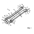
- Fig. 1 shows as basic elements of a fluid heater 1 according to the invention, a metal tube 2 and a heater 6 consisting of two identical tubular heaters 6a, 6b and a heat conducting 6c.
- the metal tube 2 has an opening 3 in a flared first end portion 4 with respect to the other metal tube enlarged cross section.
- a sealing plug or an end cap 50 are provided to close this end hermetically and pressure resistant.
- heater 6 consists of the tubular heater 6a and 6b and from the formed as a heat conducting 6c heat conduction. While the heat conduction plate 6c completely encloses the metal tube 2 in the circumferential direction, the tube heaters 6a and 6b are uniformly spaced circumferentially from opposite peripheral portions of the metal tube 2 and are each arranged with their longitudinal direction parallel to the longitudinal direction of the metal tube 2.
- the respective - preferably cold, ie unheated - ends 7a, 7b, 7c, 7d of the tubular heating elements 6a, 6b are each lifted from the metal tube 2 by means of a crank or bent away.
- substantially only the heated area of the tubular heating elements 6a, 6b is in contact with the surface of the heat conducting plate 6c.
- the cranking facilitates the contacting of the radiator 6a, 6b.
- the ends 7a, 7b, 7c, 7d of the tubular heaters 6a, 6b each have a multi-stage crimping or crimping 9a, 9b, 9c, 9d, by means of which they respectively tightly and sealingly enclose a closure bead holding the electrical connection bolts 10a, 10b, 10c, 10d.
- Fig. 2a shows the in Fig. 1
- the mounting bracket 11 encloses with brackets 12a, 12b both the tubular heater 6a and the tubular heater 6b, the heat conducting 6c and thereby fix the arrangement of the metal tube 2, the heater 6 and the mounting bracket 11 to each other, ie holds these together.
- the mounting bracket 11 has a sensor section 13 for a temperature sensor, such as an NTC sensor, on its right side in the picture a down hook 13a and on the left side in the picture two latch hooks 13b as a fastening means for a sensor.
- a temperature sensor such as an NTC sensor
- the sensor section 13 is adjoined by a first heat conducting section 14a, on which the clip sections of the clip 12a are laterally formed.
- the first heat-conducting section 14a lies substantially on the entire surface of the heat-conducting 6c.
- the clip portions of the brackets 12a, 12b are attached to about half of the longitudinal extent of the respective heat conduction portion 14a, 14b, namely, that portion which faces the opening 3 of the metal tube 2 and the stopper 5, respectively.
- the first heat-conducting section 14a is adjoined by a first connecting section 15a, which protrudes essentially S-shaped from the first heat-conducting section 14a and into a planar mounting section 16, which is substantially evenly spaced from the metal tube 2, for a securing device (such as in FIG Fig. 2B shown) and possibly a connection device such as a connector passes.
- the mounting portion 16 has through holes 17a, 17b, 17c, 17d, for example, for screws or rivets.
- a first side part 18a and a second side part 18b are angled by about 90 ° relative to the plane of the portion 16 for the connection device in the direction of the tubular heating elements 6a, 6b and each have a hole 17c and 17d.
- the first and the second side part 18a, b, a mounting tab 19a, 19b which are each bent relative to the plane of the side parts 18a and 18b slightly in the direction of the respective tubular heating elements 6a, 6b.
- the mounting tabs 19 a, 19 b each have a hole through which, for example, a grounding contact can be connected to the mounting bracket or the entire component to a mounting bracket in a household appliance, such. As a coffee maker can be fixed or fixed. The same naturally also applies to the through holes 17c and 17d in the side parts 18a, 18b.
- notch 60 in the heat conducting 6c In connection with Fig. 1 and 2a reference is still made to the notch 60 in the heat conducting 6c.
- the purpose of this notch 60 is to achieve a targeted influence on the heat transfer paths between the heating device 6 and the metal pipe terminating fluid connection assembly for the end 3 of the metal tube 2.
- the notch 60 is dimensioned so that the heat conduction from the heat conducting to the end 3 of the metal tube 2, which consists of the heat poorly conducting stainless steel is so reduced that respond in case of failure such as dry running of the fluid heater existing safety devices before, for example, an am End 3 arranged fluid connection assembly made of plastic, such as, for example, in Fig. 8a illustrated is damaged by overheating.
- Fig. 2b shows a modified embodiment of the in Fig. 2a illustrated arrangement.
- the mounting bracket 11 differs from that in the embodiment according to Fig. 2a in that the mounting portion 16 is arranged asymmetrically to the rest of the mounting bracket.
- the arrangement shown is the mounting portion 16 of Fig. 2b designed as a laterally offset relative to the central longitudinal axis of the mounting bracket 11 projecting area, which could also be referred to as a "flag" or "sheet metal flag".
- the securing device 21 attached to it in the form of a double safety device, is used in conjunction with Fig. 3 and Fig. 10 discussed in detail.
- connection device and / or safety devices on the mounting portion 16 is possible and provided. Not shown but still possible as well as in conjunction with Fig. 2a described arrangement of other side panels and / or mounting tabs.
- Fig. 2b is at both ends 3, 5 of the metal tube 2 each have a notch 60 on the top, so the viewer facing side of the fluid heater can be seen.
- the purpose of these two notches 60 is as in the embodiment in Fig. 2a in that at both ends 3, 5 of the metal tube 2 to achieve a targeted influence on the heat transfer paths between the heater 6 and the temperature sensors and / or safety devices or between the heater 6 and the metal pipe final components.
- Fig. 3 shows the in Fig. 2a illustrated arrangement supplemented by a temperature sensor 20 which is arranged in heat-conducting contact on the sensor section 13 and projects substantially perpendicularly from this.
- the temperature sensor 20 is pressed against the sensor section 13 by a fastening means in the form of a spring wire element which has two detent springs 13c, 13d and a loop 13e.
- the loop 13e engages under the down hook 13a of the mounting bracket 11 and clamps the temperature sensor 20 in cooperation with the detent springs 13c, d formed on the opposite side, which engage under a respective latch hook 13b.
- an electrical securing device 21 on the mounting portion 16 of the mounting bracket 11 by means of respective rivets 22 set firmly.
- the electrical safety device 21 has terminal lugs 21 a, 21 b, 21 c, 21 d, on the one hand based on the electrical energy from the periphery and on the other hand can be forwarded to the electrical connection pins 10 a, 10 b, 10 c, 10 d of the tubular heater.
- the safety device 21 preferably contains a fuse element for each of the connection lines, which permanently interrupts a current flow when a predetermined temperature is exceeded. Since two connection lines are provided, there are two security elements - hence the term double protection.
- FIG. 3 shows Fig. 3 to the electrical connection bolts 10a, 10b, 10c, 10d of the tubular heater 6a, 6b, for example, by spot welding fixed connection lugs, can be postponed for electrical contacting lugs.
- These terminal lugs can according to the terminal lugs 21a, 21b, 21c, 21d of the electrical safety device 21, for example, serve as plug contacts for connection to the terminal lugs 21a, 21b, 21c, 21d of the electrical safety device 21 by means of respective connecting cable.
- Fig. 4 shows the in Fig. 3 shown arrangement additionally with a fluid connection assembly 23.
- the fluid connection assembly 23 has a first fluid port 24a and a second fluid port 24b, whose respective base bodies are connected by a connection in the manner of a bayonet closure.
- a bayonet closure piece located on the main body of the first fluid port 24a and a bayonet catch counterpart 40 formed on the main body of the second fluid port 24b (see FIG FIGS. 7 and 8a )
- the first fluid port 24a and the fluid guide core 34 are locked in the fluid port assembly 23.
- first fluid port 24a is located substantially in the longitudinal axis of the metal tube 2
- second fluid port 24b is attached substantially perpendicular to the first fluid port 24a to the substantially cylindrical shell surface of a sleeve-shaped element of the fluid port assembly 23.
- a holder for a first temperature sensor 42 is set for detecting the fluid drain temperature.
- fluid ports 24a, 24b for attachment of ports of any fluid guide means comprise known locking means sized to withstand the pressure within the fluid heater.
- locking means sized to withstand the pressure within the fluid heater.
- Fig. 4 shows the closure plug 5a, for reasons of temperature resistance of metal, in particular stainless steel, or a temperature-resistant plastic, in particular a PPA (polyphthalamide), a PPS (polyphenyl sulfide), or a Made PEI (polyetherimide) and be connected by a fold 5b of the abutting edge of the metal tube 2 with this form-fitting manner.
- a temperature-resistant plastic in particular a PPA (polyphthalamide), a PPS (polyphenyl sulfide), or a Made PEI (polyetherimide)
- a “folding” is here understood to mean a cross-sectional tapering of the end of the metal tube 2 that surrounds the sealing stopper 5 as a result of plastic deformation.
- the fold forms an undercut of a circulating on the plug 5a structure and thus a positive not releasable without destroying the arrangement connection.
- the fold does not have to be completely circulating. Rather, it is sufficient if the end edge or end edge of the metal tube 2 is folded only in partial areas.
- Fig. 5 shows a plan view of in Fig. 4 illustrated and described there arrangement and defines the position of the cutting planes AA, BB and CC for in the FIGS. 6 . 8a and 9 shown sectional views.
- Fig. 6 shows a section through the section plane CC of Fig. 5 , That is, a plane perpendicular to the longitudinal axis of the metal tube 2 at the level of the safety temperature sensor 20.
- This illustration illustrates in particular the compact position of the heater 6 and realized by the metal tube 2 fluid guide.
- the central element of the illustration is a cavity arranged in the interior of a fluid guide core 30, which forms a second fluid channel section 34 for fluid guidance.
- a fluid guide core 34 associated with Fig. 7 is explained in more detail, rotates a helically guided, first fluid channel portion 35 (see Fig. 7 ), the material being cut between two adjacent sidewalls 35b on the left side, more specifically between the eight and ten o'clock positions.
- the fluid guide core 30 is fitted without play in the metal tube 2, which in turn is surrounded by the heat conducting 6c. While the metal tube 2 is made of a stainless steel, the heat conducting plate 6c has a higher thermal conductivity in which it is made of aluminum, copper or another suitable metal or a suitable metal alloy.
- the heat conducting sheet 6c may have holes or slits at suitable intervals, which allow the passage of solder or flux during the soldering operation and thus to uniformity Distribution of the solder or flux between the components lead.
- bracket 12a and (not shown in this figure) bracket 12b of the mounting bracket 11, thus providing additional communication of heat between the surface of the tubular heaters 6a, 6b and the surface of the réelleleitblechs 6c.
- bracket 12b In conjunction with the contour of the first heat-conducting section 14a adapted exactly to the section-wise contour of the heat-conducting plate 6c, improved communication of the heat generated in the tubular heating elements 6a, 6b into the heat-conducting plate 6c and further to the metal tube 2 is thus produced.
- FIG. 6 the direct contact of the sensor section 13 at the top of the réelleleitblechs 6c shown.
- the sectional view illustrates the interaction between the down hook 13a, which is engaged by the loop 13e and the latching hook 13b, which are engaged by the detent springs 13c, d in connection with the intermediate portion, the one base of the safety temperature sensor 20 firmly on the Sensor section 13 of the mounting bracket 11 presses.
- the retaining springs 13c, 13d and the loop 13e having retaining element z. B. made of wire and / or a spring steel, to ensure a suitable bias for the attachment of the safety temperature sensor 20 on the mounting bracket 11.
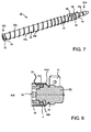
- Fig. 7 shows the in Fig. 4 introduced into the metal tube 2 fluid guide core 30 which has the first fluid port 24a in the region of a first end 31a.
- the first fluid port 24a is already in Fig. 4 shown.
- the bayonet closure counterpart 40 can be seen, which with the in Fig. 4 discussed bayonet fitting 25 cooperates.
- the bayonet closure counterpart 40 and the free area provided for locking with the bayonet closure piece 25 are adjoined by a second web 39, behind which a first sealing groove 36 for inserting or injecting sealing means is provided.
- a first web 32 is arranged, in connection with Fig. 9 will be discussed in more detail.
- a passage or opening 33 is provided, which hydraulically connects the second fluid channel section 34 arranged in the interior of the fluid guide core 30 with the first fluid channel section 35 arranged on its outside.
- cold fluid flowing inside the fluid guide core 30 may pass through the aperture 33 to the surface of the fluid guide core 30 and come into contact with the heated inside of the metal tube 2.
- the first fluid channel portion formed on the outside of the fluid guide core 30 becomes bounded by the bottom 35a and the side wall 35b.
- the first fluid channel section 35 and the side wall 35b thus wind helically or helically on the upper side of the fluid guide core 30 in the direction of the first end 31a thereof.
- the depth of the first fluid channel section 35 or the height of its side wall 35b remains essentially constant.
- the slope of the side wall 35b forming web to the fluid flow decreases, so that the ready of the first fluid passage portion 35 decreases in the direction of the first end 31 a.
- a depth change 37 in the fluid channel is formed approximately at the beginning of the penultimate line of the helical line of the first fluid channel section 35 and serves a recess and thus partial cross-sectional enlargement in the first fluid channel section 35.
- the aim of this measure is to maximize the radius for the deflection of the fluid flow and a cross-sectional adaptation to the Opening or passage 33, to avoid a so-called dead volume, so a poorly flowed through fluid channel area.
- the side wall of the fluid channel end 38 is formed in sections cylindrically in order to connect with the clear cross section of the second fluid port 24b (see. FIGS. 4 and 8a ) corresponds.
- the fluid guide core 30 is preferably made of metal, in particular stainless steel, or a temperature-resistant plastic, in particular a PPA (polyphthalamide), a PPS (polyphenyl sulfide), or a PEI (polyetherimide).
- a PPA polyphthalamide
- PPS polyphenyl sulfide
- PEI polyetherimide
- Fig. 8a shows a section along the in Fig. 5 designated AA plane through the fluid port assembly 23 along the longitudinal direction of the metal tube 2.
- the fluid port assembly 23 is a Kombifluidan gleichbauner from a first part I and a second part II, which has both the first fluid port 24a with the fluid inlet and the second fluid port 24b with the fluid outlet of the fluid heater. That is, drain and inlet are advantageously carried out on a single end face of the fluid heater.
- the substantially tubular second fluid port 24b is as in FIG Fig. 4 shown provided with a slot or a push-through, which has a latch guide groove 43-2.
- grooves 43-1, 43-2 are designed to match each other, when connecting such complementary ausgestalteter fluid connections with each other by inserting or inserting a correspondingly designed securing element such.
- a bolt (not shown) in the form of a wire spring perpendicular to the flow direction, a release of the mated terminals are prevented from each other, wherein such a connection withstands high pressures.
- the complementary design of the fluid connections 24a and 24b advantageously prevents confusion of the connections during installation in, for example, a coffee machine.
- the second part II is integrally formed on the fluid guide core 30, ie, the second part II was made in one piece with the fluid guide core 30, for example by injection molding.
- the first fluid port 24a leads fluid to be heated from the right through the second part II of the fluid port assembly 23 into the second fluid passage portion 34.
- the first part I of the fluid port assembly 23 is formed by means of a bayonet fitting 25 formed on the second fluid port 24b in cooperation with that on the second part II Bayonet catch counterpart 40 locked.
- the connection can also be made with another connection principle, such as a screw or a snap-lock connection.
- Fig. 8a is also a pure connector conceivable, since the first part I and the second part II of the fluid connection assembly 23 can be permanently fixed by the fold 44-1 of the metal tube 2 in a certain positioning to each other.
- the sectional view further shows a circumferential second web 39 and thus formed on the second part first seal groove 36, in which is provided for sealing the two parts I, II against each other a circumferential sealing means in the form of an O-ring-shaped rubber seal 41 a.
- the first part I in the second fluid connection 24b is the in Fig. 4 shown outside temperature sensor 42 is shown in a section perpendicular to its axis view. A sensor tip protrudes into the free cross-section of the second fluid port 24b and allows a precise detection of the fluid temperature in the region of the fluid outlet.
- Fig. 8a The right-hand part of the fluid guide core 30 is in connection with Fig. 7 addressed depth change 37 in the first fluid channel section 35 recognizable.
- the last course of the helix of the first fluid channel section 35 ends as a fluid channel end 38, which is positioned relative to the longitudinal axis of the second fluid port 24b, so that fluid heated with the second fluid connection can be removed in the radial direction.
- Fig. 8a the first end portion 4 with the cross-sectional enlargement of the metal pipe 2 to partially accommodate the fluid connection assembly 23 within the metal pipe 2.
- the first end portion 4 of the metal tube 2 is plastically deformed (folded) at least in sections of the peripheral end edge of the metal tube 2 to a fold.
- the metal tube 2 overlaps a seal 41b located in a second sealing groove 36a, which seals the first part against the inside of the metal tube 2.
- the fold 44-1 forms a positive locking in the form of an undercut by engaging in a third groove 45 on the outside of the fluid connection assembly 23a.
- the seal 41 b is thereby pressed by the metal tube 2 into the groove 36 a, and thus the fluid connection assembly 23 against the metal tube 2 sealed fluid-tight and pressure-tight.
- the second fluid port 24b would have to be rotated relative to the first fluid port 24a and the fluid guide core 30 and pulled off to the left in the image.
- Such twisting and thus pulling off is prevented by the fold 44-1, which undercuts a part of the first fluid connection 24a or engages in the third groove 45.
- the correct arrangement of the parts I and II of the fluid connection assembly 23 is permanently ensured.
- the fluid channel end 38 could also be embodied as a circumferential groove on the second part II, so that when a connection between the first part I and the second part II a connector, for example, a snap-lock connection (such in Fig. 8b ), the second fluid port 24b is freely rotatable with respect to its orientation on the fluid heater.
- the fluid drain can be positioned as needed in the installation eye in, for example, a coffee machine.
- FIG. 8a Of course, shown connection between the metal tube 2 and the second fluid port 24b with appropriate dimensioning without a cross-sectional enlargement 4 of the metal tube 2 can be accomplished (see also fold 44-2 in Fig. 9 ).
- the two-step cross-sectional enlargement of the free cross section of the first fluid port 24a would have to be displaced further into an area in the image to the right, ie into the second fluid channel section 34.
- the cross-sectional enlargement of the second fluid channel section 34 could first be provided in the area of the fluid guide core 30 in which the depth change 37 of the first fluid channel section is formed or the area mainly covered by the heater 6 is arranged.
- FIG. 12 illustrates an alternative embodiment of a fluid port assembly 23-1 having a first fluid port 24a in which fluid delivery into the first fluid channel portion 35 on the fluid guide core 30 is substantially the same as in FIG Fig. 8a takes place in the radial direction at the second fluid channel connection 24b. It should be noted that the actual fluid connection in Fig. 8b not shown, since this is the average of Fig. 8b lies on the side facing away from the viewer.
- the second part II of the fluid connection module 23-1 is again designed as an integral part of the fluid guide core 30.
- the connection between the first part I and the second part II is designed as a snap-lock connection.
- a circumferential locking groove 25a located on the first part I at the edge of a central through hole.
- a substantially ring-shaped rim with latching tongues 40a is provided, which each have outwardly directed latching hooks 40b.
- the latching hooks 40b engage after attaching the first part I. on the second part II in the locking groove 25a, ie undercut these and set si the first part I on the second part II.
- the first part I is compared to the second part II by means of a sealant, in Fig. 8b an O-ring seal 41 a fluid-tight and pressure-tight sealed.
- the first part is opposite to the outer surface of the metal tube by means of a sealant, in Fig. 8b an O-ring seal 41b also sealed fluid-tight and flameproof.
- a support sleeve 49 is pushed onto the metal tube 2, the right in Fig. 8b on also located on the metal tube 2 réelleleitblech 6c (in Fig. 8b not shown, cf. for example Fig. 1 ) is supported.
- a circumferential recess 36b in the first part I engages over the support sleeve 49 and forms with this a circumferential groove in which the O-ring seal 41b is arranged.
- the in Fig. 8b shown end of the metal tube 2 thermally decoupled from the heating device of the fluid heater. Since the metal tube 2 is preferably made of a stainless steel, which conducts the heat poorly, both the terminal assembly and the seal 41 b are thermally less stressed.
- a fluid port assembly 23-2 having a second fluid port 24b as a fluid drain for the heated fluid substantially identical to the fluid port assembly 23-1 of Fig. 8b can be executed.
- a fluid heater with a respective radial fluid inlet or fluid outlet can be made available in which the orientation of the connections can be set freely when the respective first parts I of the fluid connection assemblies are rotatable.
- Fig. 9 shows the sealing plug 50 of Fig. 4 at one end of the metal tube 2, which in embodiments of the fluid heater with a combination connector assembly according to the Fig. 8a is needed at the other end of the fluid heater.
- the closure plug 50 is partially inserted on its left side in the image in the opening located at the second end 31 b of a fluid guide core 30.
- a sealing means in the form of an O-ring seal 41c is arranged between the first web 32 of the fluid guide core 30 and a phase or shoulder which rotates uniformly on the sealing plug 50.
- This O-ring seal 41c may consist of a circumferential seal made of EPDM ethylene-propylene rubber, NBR (nitrile-butadiene), LSR (silicone), FFKM (perfluorinated elastomers). , FKM (fluorocarbon) or a high performance fluoroelastomer or TPE (a thermoplastic elastomer).
- a second fold 44-2 (as described above, the fold 44-1) of the abutting edge or end edge of the metal tube 2 is provided, which engages in a circumferential fourth groove 46 on the sealing plug 5.
- the second fold 44-2 prevents, as in conjunction with Fig. 8a discussed folding 44-1, a detachment of the sealing plug 50 from the metal tube 2.
- the closure cap or the sealing plug 50 is preferably made of a plastic.
- the metal tube 2 is preferably made of a stainless steel, which is a poor heat conductor, overheating, in particular softening, of the closure plug 50 made of a plastic in case of failure, for example in a dry running of the fluid heater, before responding by the double fuse 21 (see. Fig. 2B ) formed safety device or a corresponding reaction due to the means of the temperature sensor 42 (see. 3 and 4 ) detected temperature can be advantageously prevented.
- the closure plug can also be made of a metal, in particular stainless steel, in order to be able to heat the end of the metal tube 2 sealed with it as completely as possible.
- the configuration of the heat-conducting at this end of the metal tube can be omitted.
- the embodiment according to Fig. 2B without further ado to the statements according to FIGS. 2A . 3 . 4 , and 5 can be transferred, in the case of a sealing plug 50 made of a plastic or in the case of a fluid heater with respective fluid supply or fluid discharge of plastic at one end of the metal tube. 2
- Shutter plug 50 shown can also be embodied integrally with the fluid guide core 30.
- the fluid guide core 30 would then be correspondingly inserted with the integral closure plug 50 into the metal tube 2 and at the other end with the first part I (see. Fig. 8a ) of the fluid connection assembly.
- FIG. 10 shows an exploded view of an embodiment of a fluid heater according to the invention. Most features or aspects of the fluid heater are in Connection with the FIGS. 1 to 9 has already been explained in detail, which is why in the following only on individual features or differences in FIG. 10 will be discussed embodiment.
- a first fluid connection module 23-1 with a first fluid connection 24a is provided for supplying fluid at the first end 4 of the metal tube 2. Fluid which has flowed into the fluid heater via the first fluid connection subassembly 23-1 flows through the metal tube 2 essentially in one direction only (in FIG Fig. 10 from right to left) before being discharged via the second fluid port assembly 23-2 to a second fluid port 24b.
- the fluid connection assemblies 23-1 and 23-2 are sealed by means of respective sealing means in the form of O-ring seals 41 b and 41 c with the metal tube 2 fluid-tight and sufficiently pressure-tight.
- a fluid guide core 30 which is made in two parts in this exemplary embodiment and which consists of a first fluid guide core part 30a and a second fluid guide core part 30b. Via respective connecting portions 30a-1 and 30b-1, both fluid guide core parts can be firmly connected to each other.
- a part of the first connection portion 30a-1 having a reduced outside diameter is engaged with a part of a second connection portion 30b-1.
- a sealing means 41d is provided on the part of the first connecting portion 30a-1 in order to fluid-tightly connect it to the second connecting portion 30b-1.
- a bayonet closure is provided in the example.
- a snap-lock connection or a screw or a simple connector can be used.
- the two-part running fluid guide core in this case advantageously be carried out hollow, resulting in corresponding material savings.
- the respective terminal assembly 23-1 and 23-2 facing ends 70-1, 70-2 of the fluid guide core 30 are frusto-conical, with each centering or connecting nose 72-1 and 72-2 is located at the central end.
- the respective connection nose 72-1 or 72-2 engages in the assembly of the fluid heater in a corresponding bearing 74-1 of the respective terminal assembly 23-1 and 23-2.
- connection assembly 23-1 for the fluid supply recesses 24a-1 are provided in the form of circular segments for fluid passage, which merge in the connection assembly 23-1 inside in the fluid port 24a.
- webs 24a-2 are provided between the recesses 24a-1 in the form of circular segments for fluid passage, which also have the shape of circle segments and together form the bearing 74-1 for the connection nose 72-1. It should be noted that the webs 24a-2 may also have a different shape than a circle segment.
- the recesses 24a-1 in the form of circular segments for fluid passage in connection with the frusto-conical end 70-1 has proven to be particularly good in terms of flow dynamics.
- this embodiment is advantageous in the transfer from the first fluid channel section 35 into the second fluid connection subassembly 23-2 with regard to the prevention of lime deposits.
- Fig. 10 shown are electrical lines 47, with which the tubular heater 6a, 6b of the fluid heater shown are supplied with electrical energy.
- the electrical leads 47 are fastened to the electrical connections 10a, 10b, 10c, 10d of the tubular heaters.
- the contact sleeves 48a can be mechanically deformed after their positioning on the electrical terminals 10a, 10b, 10c, 10d, whereby the electrical contact resistance of the connection can be reduced.
- a connector 48b is provided at the two contact sleeves 48a opposite ends of the electrical line 47. It serves to connect the electrical line to the respective terminal lug 21a and 21d or 21b and 21c of the two fuse elements of the securing device 21.
- the connector 48b are sleeve-like and provided on its outside with an insulation.
- the tubular heaters 6a, 6b are electrically connected in parallel, so that when connecting to a voltage source, the maximum heating power is achieved.
- the first fluid port assembly 23-1 is much simpler in this embodiment. Thus, no temperature sensor is provided for measuring the temperature of the supplied fluid. However, if this is advantageous for the operation of the illustrated arrangement in view of the proposed control technology, a further temperature sensor can also be provided on the first fluid connection subassembly 23-1 corresponding to the second fluid connection subassembly 23-2.
- FIGS. 11 and 12 show in perspective partial views of a further, particularly advantageous embodiment of a fluid guide core 130 and a matching fluid port 124b.
- at least one end 131b of the fluid guide core preferably on the hot fluid discharge side, is configured frusto-conical and sunk into a funnel-like opening 125 of the fluid port 124b.
- the fluid port 124b which is in Fig. 13 is also shown in a sectional view, further comprises a subsequent to the funnel-like opening 125 fluid connection channel 126 with a preferably circular cross-section, which leads to a connection piece for a hose or other fluid discharge means.
- the transition between the opening 125 and the channel 126 may be rounded or at least deburred in order to ensure a smooth as possible and kink-free transition, which disturbs the fluid flow as little as possible.
- a connection piece or a receiving opening 127 for a temperature sensor 42 protruding into the fluid connection channel 126 or the like may be provided on the fluid connection 124b.
- the fluid channel transition arc 136 smoothly and uniformly changes the fluid flow direction from a helical motion to a substantially rectilinear motion oblique to the longitudinal axis of the fluid guide core 130.
- the fluid channel end 137 opens at the end face of the frusto-conical end 131b in the region of the longitudinal axis of the fluid guide core.
- the fluid channel course from the first fluid channel section 135 via the fluid channel transition arc 136 to the mouth of the fluid channel end piece 137 extends as smoothly as possible and preferably kink-free.
- the end face of the frusto-conical end 131b with the mouth of the fluid channel end portion is in the assembled state Condition of the fluid heater preferably close to the transition of the funnel-like opening 125 into the fluid connection channel 126, so that the exiting from the mouth fluid flow enters at an obtuse angle in the fluid connection channel 126 and abuts no baffles and sharp edges, so that it experiences little resistance and is hardly swirled.
- the flow cross-section of the fluid channel is substantially constant, starting from the helically rotating first fluid channel section 135 via the fluid channel end section 136, 137 to the mouth on the end face of the frustoconical end 131b of the fluid guide core 130.
- this flow cross section of the fluid channel end section 136, 137 may be substantially equal to the flow cross section of the fluid connection channel 126. In this way, results in a very uniform flow rate for the fluid, which is particularly advantageous on the hot fluid discharge side with regard to calcification, leaching of lime, cavitation, noise, flow resistance, etc., since no unnecessary acceleration or deceleration of the fluid due to any flow obstacles, cross-sectional changes or Turbulence occurs.
- the first fluid channel section 135 may be provided with a cross-sectional profile, in which a straight groove bottom 132 merges into an arc essentially without buckling into substantially parallel groove side walls 134.
- This transition arc is preferably in each case a quarter circle arc.
- the groove side walls 134 preferably border perpendicular to the lateral surface of the 133 of the fluid guide core.
- This cross-sectional profile preferably continues essentially unchanged in the fluid channel end section 136, 137.
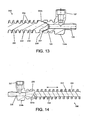
- the Fig. 13 shows another embodiment of a fluid guide core 230 with the mating fluid port 124b.
- the fluid guide core 230 is similar to the fluid guide core 130 described above, and also has a frusto-conical end 231b, a helical first fluid passage portion 235 and a fluid passage end portion 236, 237 arranged in the same manner and cooperating with the fluid port 124b in the same manner the fluid guide core 130.
- the difference from the fluid guide core 130 is that the fluid guide core 230 has a fluid channel cross-sectional profile having a curved groove bottom 232, which is preferably formed semicircular, and substantially kink-free adjoining parallel groove side walls 234 has.
- the groove side walls 234 that are rectilinear in the cross-sectional profile and to allow the arcuate groove bottom 232 to end directly on the lateral surface 233 of the fluid guide core 230.
- the parallel groove side walls 134 of the fluid guide core 130 can be made as short as desired or finally omitted altogether.
- the resulting D-shaped cross-sectional profile of the fluid channel particularly favors the achievement of the above-mentioned advantages.
- Fig. 14 shows another embodiment of a fluid guide core 330 with the mating fluid port 224b.
- the fluid guide core 330 is preferably designed in two parts and comprises a substantially cylindrical core 332 and a coil 333 placed on its lateral surface, which defines a helically rotating fluid channel section 335.
- the fluid guide core 330 may also be formed integrally in the form shown, wherein it is then preferably made of plastic, particularly preferably made of an elastomer.
- the core 332 may be made of a plastic
- the coil 333 may also be made of a plastic or metal, preferably made of steel or stainless steel.
- the coil 333 may be flexible and is preferably slid onto the core 332.
- the coil 333 may also be fixed to the core 332 under spring tension, for example.
- the core 332 has at least one conical end 331b, which in the fully assembled state of the fluid heater (1) can protrude into a funnel-like opening 225 of the fluid port 224b or not, preferably without touching the fluid port 224.
- the fluid connection 224b Similar to the fluid connection 124b, the fluid connection 224b has a fluid connection channel 226, which connects in a preferably rounded transition to the funnel-like opening 225 and leads to a connecting piece for fluid discharge means, and optionally a receiving opening 227 for eg a temperature sensor 42.
- the apex angle and thus the axial length of the conical end 331 b of the core 332 can be chosen in an advantageous development of this embodiment so that from the mouth of the funnel-like opening 225 to the transition to the fluid connection channel 226 results in a substantially constant flow cross-section.
- the fluid flow within the funnel-like opening 225 is smoothly and evenly transformed from the helical motion into a rectilinear motion in the fluid port channel 226 without any flow obstacles such as baffles and sharp edges, or abrupt ones Change of direction disturbing the flow.
- this embodiment of the fluid guide core 330 the above-mentioned advantages are achieved.
- the Fig. 18 shows a possible embodiment as a combination of the fluid guide core 330 with the fluid port 224b, as described above, and another fluid port 224a, which preferably serves as a fluid supply port.
- the fluid port 224a may be similar to the fluid port 224b with respect to the fluid guide, or alternatively may correspond to the fluid port 24a, with the end 331a of the fluid guide core 330 corresponding to the end 30b of the fluid guide core 30 in FIG Fig. 10 is trained.
- the fluid guide is less critical since generally no problems of calcification etc. occur with the relatively cold fluid.
- the core 332 may be fixedly connected to the fluid port 224a or 24a, respectively, to facilitate assembly and to ensure placement of the core 332 at the proper distance from the opposing fluid port 224b.
- the preferably flexible coil 333 can then simply be pushed onto the core 332 and be arranged with a certain axial play in the assembled fluid heater, or can be so long that it bears with light spring pressure with its two ends to the fluid ports 224a, 224b and thus fixed.
- Fig. 15 11 shows an embodiment of a fluid guide core 430 with a helically rotating first fluid channel section 435 having a variable pitch decreasing toward the fluid port 124b on the outlet side such that the flow cross section decreases in the direction of flow and the fluid is accelerated.
- the fluid guide core 430 has at the fluid outlet side a frusto-conical end 431 b which is configured in its shape and function in accordance with the frusto-conical end 131 b of the fluid guide core 130.
- the fluid guide core 430 has an end 431a like that in FIG Fig. 10 Shown end 30b of the fluid guide core 30 is designed and inserted into a fluid port 24c, with respect to the configuration of the fluid guide core receiving side of the fluid port 24a in Fig. 10 equivalent.
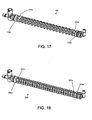
- Fig. 16 shows an embodiment of a fluid guide core 230 with a helically rotating first fluid channel section 235.
- the in Fig. 16 shown fluid guide body is provided at both ends, 231a, 231b with the frusto-conical end and the Fluidkanalendabêt 236, 237, as above with reference to the FIGS. 11 and 12 has been described, and with reference to Fig. 13 described groove profile.
- the fluid connection 124a is designed in accordance with the fluid connection 124b, in the example shown, in contrast to this, however, has an angled connecting piece for fluid supply means and has no receiving opening for a temperature sensor.
- Fig. 17 shows an embodiment similar to that of Fig. 16 However, here the above with respect to the FIGS. 11 and 12 described fluid guide core 130 is used with the other groove profile and a larger pitch of the helically encircling first fluid channel portion 135.
- the configuration of the fluid guide core in terms of groove cross-sectional profile and pitch of the helically encircling groove, as in Fig. 16 and 17 shown varied within wide ranges, so as to adjust the hydraulic length of the heated first fluid channel section. In this way, in particular the dynamic behavior and thus the controllability of the fluid heater can be optimized for different operating conditions.
- Fig. 19 shows a further embodiment in which the fluid guide core 530 has no helically rotating fluid channel section. Rather, the fluid channel is configured in the form of a uniform annular space between a cylindrical portion 532 (soul) of the fluid guide core 530 and the metal tube 2, wherein the fluid guide core 530 on the cylindrical portion 532 arranged spacer ribs 533 to center the fluid guide core 530 in the metal tube 2 and to keep.
- spacer ribs 533 which can extend over the entire length of the cylindrical gate 532 or as shown only over a part thereof in the axial direction come in the function of the helix 333 of the fluid guide core 330 same, with the difference that there is no helically rotating fluid flow, but gives a substantially rectilinear fluid flow in the annulus. It is also a slight inclination of these spacer ribs to the axial direction possible, so that there is a helical fluid flow with only a few revolutions or even a fraction of a full round about the central longitudinal axis.
- a multi-pass first fluid channel section runs next to one another around the cylindrical section, wherein the individual passages are separated by the spacer ribs 533 (multi-turn helix).
- the fluid guide core 530 may be attached to a fluid port 24c as described with reference to FIGS Fig. 15 described designed is to be defined in a defined position with a certain distance to the opposite fluid port 124b. It is also possible that the fluid guide core is simply inserted up to a certain position in the metal tube 2 and held there in position due to a clamping action by means of the spacer ribs.
- the fluid guide core 530 has at the fluid outlet end a tapered end 531b which cooperates with the fluid port 124b in a similar configuration and function as the tapered end 331b of the fluid guide core 330 described above with respect to FIG Fig. 14 has been described.
- This embodiment also results in a particularly gentle and substantially kink-free fluid guide with the advantages mentioned above.
- the hydraulic length of a fluid heater with such a fluid guide core 530 is significantly shorter than in the other embodiments, which may be sufficient under certain operating conditions.
- the particular advantage of this variant of the fluid guide core is its simple shape, which is particularly easy to manufacture, which also results in a particularly low flow resistance.
- a fluid guide core between the in Fig. 15 and Fig. 19 shown core shapes 430 and 530 possible, with variable pitch or kontant slope of the helical circumferential fluid channel sections, and with a tapered end 531 b or with a frusto-conical end 431 b, which has one or more Fluidendkanatabitese corresponding to the Fluidkanalendaboughe 136, 137, according to a catchy or multi-trained first fluid channel section, as has been described in the preceding paragraph.
- a two-part fluid guide core is not limited to embodiments in which the fluid supply and the fluid discharge take place on opposite sides of the metal tube.
- a two-part fluid guide core is not limited to embodiments in which the fluid supply and the fluid discharge take place on opposite sides of the metal tube.
- notch 60 of the are provided if necessary in other embodiments.
Claims (13)
- Dispositif (1) de chauffe de fluide du type instantané, le dispositif de chauffe de fluide comprenant :un canal pour du fluide ayant au moins un premier tronçon (135; 235),au moins un tuyau (2) métallique sensiblement cylindrique, de préférence en acier fin, et, d'une manière particulièrement préférée, d'un diamètre de 10 mm à 20 mm, ainsi que d'une longueur de 120 mm à 220 mm,un dispositif (6) de chauffage ayant au moins un corps de chauffe tubulaire, de préférence ayant au moins deux corps (6a, 6b) de chauffe tubulaires à distance l'un de l'autre sur des parties périphériques équidistantes du tuyau (2) métallique et des moyens de conduction de la chaleur pour répartir la chaleur du dispositif (6) de chauffage à des parties du tuyau (2) métallique en contact avec les moyens de conduction de la chaleur,un noyau (130; 230) de conduite de fluide, de préférence en matière plastique, qui est disposé dans le tuyau (2) métallique et qui forme le premier tronçon (135; 235) de canal pour du fluide entre le tuyau métallique et le noyau (130; 230) de conduite de fluide etun premier raccord (124a) pour du fluide pour un moyen d'apport de fluide et un deuxième raccord (124b) pour du fluide pour un moyen d'évacuation du fluide, qui communiquent avec les extrémités respectives du canal pour du fluide,le premier tronçon (135) de canal pour du fluide s'étendant sensiblement en forme d'hélice sous la forme d'une rainure dans une surface extérieure du noyau de conduite de fluide et le premier tronçon (135) de canal pour du fluide formant une voie d'écoulement pour le fluide ayant une longueur hydraulique, qui, de préférence, est à peu près deux fois, d'une manière particulièrement préférée au moins environ trois fois, aussi grande que la longueur du tuyau (2) métallique etdans lequel le noyau (130; 230) de conduite de fluide a au moins une extrémité (131,; 231b) sensiblement tronconique, qui a un tronçon (136, 137; 236, 237) d'extrémité de canal pour du fluide, lequel est constitué sous la forme d'un prolongement sensiblement sans coude du premier tronçon (135; 235) de canal pour du fluide et débouche à la surface frontale de l'extrémité (131b; 231b) tronconique.
- Dispositif (1) de chauffe instantané d'un fluide suivant la revendication 1,
dans lequel au moins l'un des raccords (124b) pour du fluide a une ouverture (125) sensiblement en entonnoir, dans laquelle l'extrémité (131b; 231b) tronconique du noyau (130; 230) de conduite de fluide est enfoncée et un canal (126) de raccord pour du fluide, qui se raccorde à l'ouverture (125) en entonnoir et qui mène à une tubulure de raccordement d'un moyen d'apport de fluide ou d'un moyen d'évacuation de fluide, la transition entre l'ouverture (125) en entonnoir et le canal (126) de raccord pour du fluide étant, de préférence, arrondie. - Dispositif (1) de chauffe instantané d'un fluide suivant l'une des revendications précédentes 1 ou 2,
dans lequel la section transversale d'écoulement, en partant de l'extrémité du premier tronçon (135; 235) de canal pour du fluide jusqu'à l'embouchure du tronçon (136, 137; 236, 237) d'extrémité de canal pour du fluide dans la surface frontale de l'extrémité (131b; 231b) tronconique, est sensiblement constante. - Dispositif (1) de chauffe instantané d'un fluide suivant l'une des revendications précédentes 1 à 3,
dans lequel la section transversale d'écoulement à l'embouchure du tronçon (136, 137; 236, 237) d'extrémité de canal pour du fluide est sensiblement égale à la section transversale d'écoulement du canal (126) de raccordement pour du fluide. - Dispositif (1) de chauffe instantané d'un fluide suivant l'une des revendications précédentes 1 à 4,
dans lequel le premier tronçon (135) de canal pour du fluide est constitué sous la forme d'une rainure de la surface extérieure du noyau (130) de conduite de fluide et, dans la section transversale de la rainure, la transition entre un fond (132) de rainure et des parois (134) latérales des rainures sensiblement parallèles est arrondie et, de préférence, est en forme d'arc de cercle, de sorte que les parois (134) latérales de la rainure se transforment sensiblement sans coude en le fond (132) de la rainure. - Dispositif (1) de chauffe instantané d'un fluide suivant l'une des revendications précédentes 1 à 4,
dans lequel le premier tronçon (235) de canal pour du fluide est constitué sous la forme d'une rainure dans la surface extérieure du noyau (230) de conduite de fluide et, dans la section transversale de la rainure, un fond (232) de rainure est courbé et est, de préférence, en forme d'arc de cercle et se transforme sensiblement sans coude en des parois (234) latérales de rainure sensiblement parallèles. - Dispositif (1) de chauffe instantané d'un fluide suivant l'une des revendications précédentes 1 à 6,
dans lequel la forme de la section transversale du premier tronçon (335) de canal pour du fluide se poursuit sensiblement sans modification dans le tronçon (136, 137; 236, 237) d'extrémité de canal pour du fluide. - Dispositif (1) de chauffe de fluide du type instantané, le dispositif de chauffe de fluide comprenant .
un canal pour du fluide ayant au moins un premier tronçon (335),
au moins un tuyau (2) métallique sensiblement cylindrique, de préférence en acier fin, et, d'une manière particulièrement préférée, d'un diamètre de 10 mm à 20 mm, ainsi que d'une longueur de 120 mm à 220 mm,
un dispositif (6) de chauffage ayant au moins un corps de chauffe tubulaire, de préférence ayant au moins deux corps (6a, 6b) de chauffe tubulaires à distance l'un de l'autre sur des parties périphériques équidistantes du tuyau (2) métallique et des moyens de conduction de la chaleur pour répartir la chaleur du dispositif (6) de chauffage à des parties du tuyau (2) métallique en contact avec les moyens de conduction de la chaleur,
un noyau (330) de conduite de fluide, de préférence en matière plastique, qui est disposé dans le tuyau (2) métallique et qui forme le premier tronçon (335) de canal pour du fluide entre le tuyau métallique et le noyau (330) de conduite de fluide et
un premier raccord (224a) pour du fluide pour un moyen d'apport de fluide et un deuxième raccord (224b) pour du fluide pour un moyen d'évacuation du fluide, qui communiquent avec les extrémités respectives du canal pour du fluide,
le premier tronçon (335) de canal pour du fluide s'étendant sensiblement en forme d'hélice sous la forme d'une rainure dans une surface extérieure du noyau de conduite de fluide et le premier tronçon (335) de canal pour du fluide formant une voie d'écoulement pour le fluide ayant une longueur hydraulique, qui, de préférence, est à peu près deux fois, d'une manière particulièrement préférée au moins environ trois fois, aussi grande que la longueur du tuyau (2) métallique et
le noyau (330) de conduite de fluide ayant une âme (332) cylindrique et un serpentin (333), qui y est disposé et qui forme le premier tronçon (335) de canal de conduite du fluide entourant en forme d'hélice le noyau (330) de conduite de fluide, l'âme (332) ayant au moins une extrémité (331b) sensiblement en forme de cône, qui pénètre en partie dans une ouverture (225) sensiblement en entonnoir du raccord (224b) pour du fluide. - Dispositif (1) de chauffe instantané d'un fluide suivant la revendication 8,
dans lequel l'angle aigu de l'extrémité (331b) conique de l'âme (332) est choisi de manière à donner une section transversale d'écoulement sensiblement constante dans l'ouverture (225) en entonnoir de l'embouchure jusqu'à une transition à un canal (226) de raccord pour du fluide. - Dispositif (1) de chauffe instantané d'un fluide suivant la revendication 8 ou 9,
dans lequel l'âme (332) du noyau (330) de conduite de fluide est en matière plastique. - Dispositif (1) de chauffe instantané d'un fluide suivant la revendication 10,
dans lequel le serpentin (333) du noyau (330) de conduite de fluide est en matière plastique. - Dispositif (1) de chauffe instantané d'un fluide suivant la revendication 10,
dans lequel le serpentin (333) du noyau (330) de conduite de fluide est en métal, de préférence en acier. - Dispositif (1) de chauffe instantané d'un fluide suivant la revendication 11,
dans lequel le noyau (330) de conduite de fluide est d'une seule pièce en une matière plastique, de préférence en un élastomère.
Priority Applications (1)
| Application Number | Priority Date | Filing Date | Title |
|---|---|---|---|
| EP11732379.0A EP2592982B1 (fr) | 2010-07-12 | 2011-07-12 | Dispositif de chauffe instantané dynamique |
Applications Claiming Priority (3)
| Application Number | Priority Date | Filing Date | Title |
|---|---|---|---|
| EP10007164A EP2407069A1 (fr) | 2010-07-12 | 2010-07-12 | Chauffe-eau instantané dynamique |
| EP11732379.0A EP2592982B1 (fr) | 2010-07-12 | 2011-07-12 | Dispositif de chauffe instantané dynamique |
| PCT/EP2011/003482 WO2012007155A2 (fr) | 2010-07-12 | 2011-07-12 | Dispositif de chauffe instantané dynamique |
Publications (2)
| Publication Number | Publication Date |
|---|---|
| EP2592982A2 EP2592982A2 (fr) | 2013-05-22 |
| EP2592982B1 true EP2592982B1 (fr) | 2015-04-22 |
Family
ID=43466584
Family Applications (2)
| Application Number | Title | Priority Date | Filing Date |
|---|---|---|---|
| EP10007164A Withdrawn EP2407069A1 (fr) | 2010-07-12 | 2010-07-12 | Chauffe-eau instantané dynamique |
| EP11732379.0A Active EP2592982B1 (fr) | 2010-07-12 | 2011-07-12 | Dispositif de chauffe instantané dynamique |
Family Applications Before (1)
| Application Number | Title | Priority Date | Filing Date |
|---|---|---|---|
| EP10007164A Withdrawn EP2407069A1 (fr) | 2010-07-12 | 2010-07-12 | Chauffe-eau instantané dynamique |
Country Status (5)
| Country | Link |
|---|---|
| US (1) | US9664414B2 (fr) |
| EP (2) | EP2407069A1 (fr) |
| CN (1) | CN103153146B (fr) |
| HK (1) | HK1185523A1 (fr) |
| WO (1) | WO2012007155A2 (fr) |
Families Citing this family (28)
| Publication number | Priority date | Publication date | Assignee | Title |
|---|---|---|---|---|
| US8755679B2 (en) * | 2006-04-05 | 2014-06-17 | Horiba Stec, Co., Ltd. | Liquid material vaporizer |
| DE102010032189A1 (de) * | 2010-07-23 | 2012-01-26 | Voss Automotive Gmbh | Beheizbare Medienleitung und Verfahren zu deren Herstellung |
| WO2013170887A1 (fr) * | 2012-05-15 | 2013-11-21 | Bleckmann Gmbh & Co. Kg | Élément chauffant à circulation directe dynamique hélicoïdal |
| CN105555499B (zh) * | 2013-05-29 | 2017-09-12 | 圣万提注塑工业(苏州)有限公司 | 阀销位置调节器 |
| FR3008032B1 (fr) * | 2013-07-02 | 2015-07-17 | Valeo Systemes Thermiques | Dispositif de conditionnement thermique de fluide pour vehicule automobile et appareil de chauffage et/ou de climatisation correspondant |
| US9638438B2 (en) * | 2013-07-09 | 2017-05-02 | Cast Aluminum Solutions, LLC | Circulation heater |
| CN203898082U (zh) * | 2014-01-14 | 2014-10-29 | 宁波金阳光电热科技有限公司 | 压力式液体速热器 |
| EP2896882B1 (fr) * | 2014-01-15 | 2022-06-01 | Electrolux Appliances Aktiebolag | Générateur de vapeur et appareil électroménager |
| CN103822648B (zh) * | 2014-03-14 | 2016-07-06 | 厦门易感智能测控技术有限公司 | 传感器 |
| CN103976659A (zh) * | 2014-05-16 | 2014-08-13 | 冯海涛 | 智能型饮水加热装置 |
| KR20160001614A (ko) * | 2014-06-26 | 2016-01-06 | 엘지전자 주식회사 | 가전제품 |
| US20160000252A1 (en) * | 2014-07-02 | 2016-01-07 | As Wilfa | Pump and heating method and arrangement for coffee brewing |
| EP3013116A1 (fr) * | 2014-10-21 | 2016-04-27 | Bleckmann GmbH & Co. KG | Composant de système de chauffage et son procédé de production |
| CN106766117B (zh) * | 2015-11-24 | 2022-05-06 | 三花亚威科电器设备(芜湖)有限公司 | 一种管路电加热器及具有其的洗碗机 |
| JP6675865B2 (ja) * | 2015-12-11 | 2020-04-08 | 株式会社堀場エステック | 液体材料気化装置 |
| US10247445B2 (en) * | 2016-03-02 | 2019-04-02 | Watlow Electric Manufacturing Company | Heater bundle for adaptive control |
| EP3540329B1 (fr) * | 2016-06-20 | 2021-04-28 | Bleckmann GmbH & Co. KG | Composant de système de chauffage fournissant une conception de capteur de température compact |
| IT201700060931A1 (it) * | 2017-06-05 | 2018-12-05 | Lavazza Luigi Spa | Riscaldatore per fluidi e corrispondente macchina |
| CN107186932A (zh) * | 2017-07-26 | 2017-09-22 | 江苏苏高流体机械有限公司 | 一种高效浇铸的引导管 |
| DE102017214932A1 (de) * | 2017-08-25 | 2019-02-28 | BSH Hausgeräte GmbH | Dampfgargerät |
| CN110224536B (zh) * | 2018-03-02 | 2024-03-22 | 日本电产三协电子(东莞)有限公司 | 电机 |
| CN108826658B (zh) * | 2018-07-02 | 2023-11-07 | 嘉兴志嘉智能电器有限公司 | 全水体安全接地的即热式加热器及其加热方法 |
| RU2684907C1 (ru) * | 2018-07-06 | 2019-04-16 | Акционерное общество "Ордена Трудового Красного Знамени и ордена труда ЧССР опытное конструкторское бюро "ГИДРОПРЕСС" | Ошиновка блока трубчатых электронагревателей |
| EP3620097B1 (fr) * | 2018-09-07 | 2021-08-25 | Bleckmann GmbH & Co. KG | Système de chauffage destiné à chauffer un milieu fluide |
| WO2020175564A1 (fr) * | 2019-02-28 | 2020-09-03 | 京セラ株式会社 | Unité d'échange de chaleur et dispositif de nettoyage doté de ladite unité |
| EP3702691B1 (fr) * | 2019-02-28 | 2023-11-15 | Gerdes Holding GmbH & Co. KG | Chauffe-eau instantané pour réchauffer un liquide |
| CN111714058A (zh) * | 2019-03-22 | 2020-09-29 | 青岛海尔洗碗机有限公司 | 一种洗碗机水路加热器及应用其的洗碗机 |
| US20220034549A1 (en) * | 2020-07-29 | 2022-02-03 | Tom Richards, Inc. | Inline heater |
Family Cites Families (78)
| Publication number | Priority date | Publication date | Assignee | Title |
|---|---|---|---|---|
| US1946547A (en) * | 1931-12-14 | 1934-02-13 | Vapor Car Heating Co Inc | Steam and electric heating unit |
| US2445115A (en) | 1944-04-07 | 1948-07-13 | Us Agriculture | Heat exchanger |
| US2513242A (en) * | 1945-10-11 | 1950-06-27 | Hollis C Inman | Electric fluid heater |
| US2687626A (en) | 1952-02-16 | 1954-08-31 | Bohn Aluminium & Brass Corp | Heat exchanger having open-sided bore superimposed on closed bore |
| US2890318A (en) | 1955-08-24 | 1959-06-09 | Ferro Corp | Aluminum sheathed heating elements in aluminum die castings |
| US2875312A (en) | 1956-09-27 | 1959-02-24 | Thermel Inc | Heating assembly and method of production thereof |
| US2878360A (en) * | 1957-08-15 | 1959-03-17 | Walter K Tavender | Portable steam guns and steam-superheating apparatus therefor |
| US2944138A (en) | 1957-12-23 | 1960-07-05 | Electric Heaters Inc | Electric space heater and method of manufacture |
| AT238841B (de) * | 1960-02-10 | 1965-03-10 | Siemens Elektrogeraete Gmbh | Elektrischer Durchlauferhitzer |
| DE2023598C3 (de) | 1970-05-14 | 1976-01-02 | Bosch-Siemens Hausgeraete Gmbh, 7000 Stuttgart | Elektrischer Durchlauferhitzer für Kaffeemaschinen |
| US3718805A (en) * | 1971-01-13 | 1973-02-27 | E Posey | Heated fluid gun |
| DE2340489A1 (de) | 1973-08-10 | 1975-02-20 | Braun Ag | Elektrischer durchflusserhitzer |
| DE2356307A1 (de) | 1973-11-10 | 1975-05-15 | Stiebel Eltron Gmbh & Co Kg | Elektrischer durchlauferhitzer mit wendelfoermigem wasserdurchlauf |
| DE2460189C2 (de) | 1974-12-19 | 1985-11-14 | Siemens AG, 1000 Berlin und 8000 München | Durchlauferhitzer einer elektrischen Kaffeemaschine |
| US4203186A (en) * | 1975-02-07 | 1980-05-20 | Exxon Research & Engineering Co. | Heat transfer |
| DE7536932U (de) | 1975-11-20 | 1976-05-06 | Elpag Ag Chur, Chur (Schweiz) | Durchlauferhitzer fuer kaffeemaschinen oder andere elektrisch beheizte haushaltsgeraete |
| US4052590A (en) | 1976-10-28 | 1977-10-04 | National Presto Industries, Inc. | Electric appliance with intermittently staked sheathed heating element |
| DE7726863U1 (de) | 1977-08-30 | 1977-12-01 | Siemens Ag, 1000 Berlin Und 8000 Muenchen | Elektrischer durchlauferhitzer fuer kaffeemaschinen |
| DE2743333A1 (de) | 1977-09-27 | 1979-03-29 | Brunsemann Karl Ernst | Vorrichtung zur rueckgewinnung von waermeenergie aus dem abwasser von waschbecken, spuelbecken, bidets, duschen und anderen sanitaeren einrichtungen |
| US4170901A (en) * | 1978-06-15 | 1979-10-16 | The United States Of America As Represented By The Secretary Of The Air Force | Sorption tube atmospheric sampling system |
| US4395882A (en) | 1978-11-13 | 1983-08-02 | Sunspool Corporation | Freeze protection apparatus for solar collectors |
| DE2903743C2 (de) | 1979-02-01 | 1984-07-05 | Türk & Hillinger GmbH & Co, 7200 Tuttlingen | Verfahren zum Herstellen eines elektrischen Durchlauferhitzers |
| DE2942523C2 (de) * | 1979-10-20 | 1981-11-19 | Türk & Hillinger GmbH & Co, 7200 Tuttlingen | Elektrischer Durchlauferhitzer |
| JPS56116608A (en) * | 1980-02-21 | 1981-09-12 | Toshiba Corp | Electromagnetic pump |
| US4417133A (en) | 1981-02-24 | 1983-11-22 | Sanner Johnny W | Fuel tank having an immersion heating element assembly |
| US4563571A (en) * | 1981-12-16 | 1986-01-07 | Matsushita Electric Industrial Company, Limited | Electric water heating device with decreased mineral scale deposition |
| US4460819A (en) | 1983-01-11 | 1984-07-17 | Intropa Trading S.A. | Instantaneous flow-through electric water heater for coffee makers |
| DE8310976U1 (de) | 1983-04-13 | 1983-09-01 | Elpag AG Chur, 7001 Chur | Elektrischer Durchlauferhitzer für Haushaltsgeräte, insbesondere Kaffeemaschinen |
| DE3419365C1 (de) | 1984-05-24 | 1985-09-05 | Melitta-Werke Bentz & Sohn, 4950 Minden | Durchlauferhitzer fuer eine Kaffee- oder Teemaschine |
| US4693302A (en) * | 1984-12-28 | 1987-09-15 | Leonard Oboler | Heat exchanging apparatus for cooling and condensing by evaporation |
| DE3509609A1 (de) | 1985-03-16 | 1986-09-18 | Dürr-Dental GmbH & Co KG, 7120 Bietigheim-Bissingen | Vorrichtung zum temperieren einer mehrzahl von fluessigkeiten |
| DE3542507A1 (de) | 1985-12-02 | 1987-06-04 | Tuerk & Hillinger Gmbh | Elektrischer durchlauferhitzer |
| DE8536338U1 (de) | 1985-12-23 | 1986-03-27 | Elpag Ag Chur, Chur | Elektrischer Druchlauferhitzer |
| DE3637378A1 (de) | 1986-11-03 | 1988-05-05 | Braun Ag | Elektrischer durchlauferhitzer fuer geraete des persoenlichen bedarfs |
| CH674305A5 (fr) | 1987-08-14 | 1990-05-31 | Turmix Ag | |
| ATE98153T1 (de) | 1990-03-03 | 1993-12-15 | Guenther Herbert Gmbh | Verteiler. |
| GB9024419D0 (en) | 1990-11-09 | 1991-01-02 | Ist Lab Ltd | Heating apparatus |
| DE4130447A1 (de) | 1991-09-13 | 1993-03-25 | Braun Ag | Wasserkessel |
| US5523550A (en) * | 1992-01-06 | 1996-06-04 | Kimura; Todd T. | Capacitive induction heating method and apparatus for the production for instant hot water and steam |
| CN1076326A (zh) | 1992-03-12 | 1993-09-15 | 淄博电热电器厂 | 复合式电加热盘成型工艺及电加热盘 |
| DE4212074C1 (en) * | 1992-04-10 | 1993-04-29 | Tuerk & Hillinger Gmbh, 7200 Tuttlingen, De | Electric continuous flow meter e.g. for coffee machine - has tubular heaters pressed so that walls of flow tube have recesses altering cross-section |
| DE4332826A1 (de) * | 1993-09-27 | 1995-03-30 | Elpag Ag Chur | Durchlauferhitzer mit Einschnürungen |
| US5949958A (en) * | 1995-06-07 | 1999-09-07 | Steris Corporation | Integral flash steam generator |
| DE19523047C1 (de) * | 1995-06-24 | 1996-11-21 | Tuerk & Hillinger Gmbh | Elektrischer Durchlauferhitzer für flüssige Medien |
| DE19726245C2 (de) * | 1997-06-20 | 1998-08-13 | Bosch Siemens Hausgeraete | Vorrichtung zum Erhitzen von Flüssigkeit |
| FR2778729B1 (fr) | 1998-05-15 | 2003-12-05 | Moulinex Sa | Chaudiere pour appareil electromenager et appareil electromenager comportant une telle chaudiere |
| DE19852888A1 (de) * | 1998-11-17 | 2000-05-31 | Braun Gmbh | Heizeinrichtung für ein wassererhitzendes Haushaltsgerät |
| US6098666A (en) | 1999-01-13 | 2000-08-08 | Parker-Hannifin Corporation | Dual coil tubing assembly |
| CN2397425Y (zh) * | 1999-09-21 | 2000-09-20 | 洪陵成 | 流体加热器 |
| US6459854B1 (en) * | 2000-01-24 | 2002-10-01 | Nestec S.A. | Process and module for heating liquid |
| CN2407296Y (zh) * | 2000-02-23 | 2000-11-22 | 淮阴辉煌太阳能有限公司 | 热泵式热水器 |
| US6943325B2 (en) | 2000-06-30 | 2005-09-13 | Balboa Instruments, Inc. | Water heater |
| CN1122161C (zh) * | 2001-02-28 | 2003-09-24 | 辜志花 | 带冷却装置和能量调节装置的热泵式热水器 |
| JP4364461B2 (ja) | 2001-08-08 | 2009-11-18 | 株式会社コロナ | 電気自動車及びハイブリッド車用温水暖房装置 |
| DE20120611U1 (de) | 2001-12-20 | 2003-02-13 | Eichenauer Gmbh & Co Kg F | Heizsystem für einen Dampferzeuger |
| US6967315B2 (en) * | 2002-06-12 | 2005-11-22 | Steris Inc. | Method for vaporizing a fluid using an electromagnetically responsive heating apparatus |
| US6701068B2 (en) | 2002-07-24 | 2004-03-02 | Uni-Splendor Corp. | Double heating device for coffee maker |
| EP1400762B1 (fr) | 2002-09-19 | 2016-04-13 | Adams Rite Aerospace, Inc. | Système de chauffage d'eau pour aéronefs |
| CA2466624C (fr) | 2003-05-07 | 2007-01-02 | Dale H. Pickard | Douille de tube d'eau chaude et systeme de panneaux chauffants a chaleur rayonnante |
| DE20321667U1 (de) * | 2003-05-16 | 2008-10-09 | Stiebel Eltron Gmbh & Co. Kg | Flüssigkeitserhitzer |
| FR2855359B1 (fr) | 2003-05-19 | 2005-07-01 | Seb Sa | Dispositif de chauffage d'un liquide pour appareil electromenager, appareil electromenager equipe d'un tel dispositif. |
| EP1532905A1 (fr) * | 2003-11-20 | 2005-05-25 | Steiner AG Weggis | Dispositif pour alimenter de l'eau chaude, de la vapeur ou du lait chaud à une machine à café |
| WO2005057090A1 (fr) * | 2003-12-10 | 2005-06-23 | Matsushita Electric Industrial Co., Ltd. | Echangeur thermique et dispositif d'epuration |
| JP2006336886A (ja) | 2005-05-31 | 2006-12-14 | Nippon Oil Corp | 複合式ヒータおよび該複合式ヒータを備えた暖房システム |
| FR2891688B1 (fr) | 2005-10-05 | 2007-11-30 | Seb Sa | Dispositif de chauffage de fluide avec fusible thermique |
| FR2891720B1 (fr) * | 2005-10-06 | 2007-12-14 | Seb Sa | Dispositif de chauffage de liquide pour appareil electromenager. |
| DE102005050203B4 (de) * | 2005-10-18 | 2018-05-24 | Eichenauer Heizelemente Gmbh & Co. Kg | Verfahren zur Herstellung eines Durchflusserhitzers und Durchflusserhitzer |
| ITVE20060016U1 (it) | 2006-05-18 | 2007-11-19 | Irca Spa | Elemento riscaldante.- |
| DE202007005738U1 (de) * | 2007-04-20 | 2007-07-12 | Eugster/Frismag Ag | Durchlaufwärmetauscher zur Zubereitung von Getränken, insbesondere Wasser-Durchlauferhitzer für Kaffeezubereitungsmaschinen |
| DE102007034370A1 (de) | 2007-07-24 | 2009-01-29 | Bleckmann Gmbh & Co. Kg | Kompakte hochdruckfähige Spiraldurchfluss-Heizeinheit |
| CN201212728Y (zh) * | 2008-05-23 | 2009-03-25 | 黄樟焱 | 新型流动液体电加热器 |
| US20100046934A1 (en) * | 2008-08-19 | 2010-02-25 | Johnson Gregg C | High thermal transfer spiral flow heat exchanger |
| DE102009037828A1 (de) * | 2008-11-11 | 2010-05-20 | Wurz, Dieter, Prof. Dr. | Zweistoffdüse, Bündeldüse und Verfahren zum Zerstäuben von Fluiden |
| DE202009015187U1 (de) * | 2008-11-14 | 2010-06-24 | Koninklijke Philips Electronics N.V. | Einsatzteil für einen Durchlauferhitzer |
| AU2009322122A1 (en) | 2008-12-06 | 2010-06-10 | 3Ip, Pllc | Improved heat transfer between tracer and pipe |
| US8208800B2 (en) * | 2009-03-16 | 2012-06-26 | Hsien Mu Chiu | Potable water heating device |
| ITRM20110514A1 (it) | 2011-09-29 | 2013-03-30 | I R C A S P A Ind Resistenz E Corazzate E | Profilato per un riscaldatore e riscaldatore a flusso di fluidi, in particolare per macchine da caffe' |
| WO2013170887A1 (fr) | 2012-05-15 | 2013-11-21 | Bleckmann Gmbh & Co. Kg | Élément chauffant à circulation directe dynamique hélicoïdal |
-
2010
- 2010-07-12 EP EP10007164A patent/EP2407069A1/fr not_active Withdrawn
-
2011
- 2011-07-12 CN CN201180034651.7A patent/CN103153146B/zh not_active Expired - Fee Related
- 2011-07-12 EP EP11732379.0A patent/EP2592982B1/fr active Active
- 2011-07-12 WO PCT/EP2011/003482 patent/WO2012007155A2/fr active Application Filing
- 2011-07-12 US US13/634,191 patent/US9664414B2/en not_active Expired - Fee Related
-
2013
- 2013-11-21 HK HK13113021.1A patent/HK1185523A1/xx not_active IP Right Cessation
Also Published As
| Publication number | Publication date |
|---|---|
| CN103153146B (zh) | 2016-04-06 |
| US9664414B2 (en) | 2017-05-30 |
| CN103153146A (zh) | 2013-06-12 |
| US20130202279A1 (en) | 2013-08-08 |
| HK1185523A1 (en) | 2014-02-21 |
| WO2012007155A2 (fr) | 2012-01-19 |
| EP2407069A1 (fr) | 2012-01-18 |
| WO2012007155A3 (fr) | 2012-04-12 |
| EP2592982A2 (fr) | 2013-05-22 |
Similar Documents
| Publication | Publication Date | Title |
|---|---|---|
| EP2592982B1 (fr) | Dispositif de chauffe instantané dynamique | |
| EP3334242B1 (fr) | Dispositif de chauffage électrique | |
| DE102012107600B4 (de) | Elektrische Heizvorrichtung zum Beheizen von Fluiden | |
| EP1777452B1 (fr) | Connecteur chauffable | |
| EP2410813B1 (fr) | Radiateur électrique et chauffe-eau instantané | |
| EP2917555B1 (fr) | Dispositif de préchauffage destiné à un système d'injection de carburant | |
| EP2706280B1 (fr) | Connecteur enfichable | |
| EP2171337A2 (fr) | Conduite à fluides surmoulée | |
| EP3397904B1 (fr) | Chauffe-eau instantané | |
| EP3611738A1 (fr) | Manchon de refroidissement pour conduite d'énergie | |
| EP2489534B1 (fr) | Agencement d'échangeur thermique, notamment pour un appareil de chauffage de véhicule fonctionnant au carburant | |
| EP3510674A1 (fr) | Élément de contact électriquement conducteur pour connecteur électrique | |
| EP4010617A1 (fr) | Ensemble de serrage doté d'un dispositif de protection thermique | |
| EP2061119B1 (fr) | Elément de contact et procédé de fabrcation | |
| DE3427207C2 (fr) | ||
| WO2016087054A2 (fr) | Système de chauffage pour une conduite de guidage de fluide | |
| EP2211588A1 (fr) | Element de contact pour spirale chauffante d'un element chauffant tubulaire et son procede de fabrication | |
| DE102007036533B4 (de) | Fluidleitungskupplung | |
| DE102010043222B4 (de) | Brennkammerbaugruppe und Zündorgan dafür | |
| EP1703227A2 (fr) | Echangeur de chaleur | |
| DE102005026919A1 (de) | Flanschloser Kunststoff-Boiler | |
| DE102004021667A1 (de) | Schlauchverbindungssystem für einen beheizbaren Schlauch | |
| EP1731850A2 (fr) | Chaudière en matière plastique sans bride | |
| DE102011081401B4 (de) | Wärmetauscheranordnung, insbesondere für ein brennstoffbetriebenes Fahrzeugheizgerät | |
| DE102018121047A1 (de) | Verbindungsanordnung eines Rohranschlusses an einem Haustechnikgerät sowie Haustechnikgerät mit einer solchen Verbindungsanordnung |
Legal Events
| Date | Code | Title | Description |
|---|---|---|---|
| PUAI | Public reference made under article 153(3) epc to a published international application that has entered the european phase |
Free format text: ORIGINAL CODE: 0009012 |
|
| 17P | Request for examination filed |
Effective date: 20130212 |
|
| AK | Designated contracting states |
Kind code of ref document: A2 Designated state(s): AL AT BE BG CH CY CZ DE DK EE ES FI FR GB GR HR HU IE IS IT LI LT LU LV MC MK MT NL NO PL PT RO RS SE SI SK SM TR |
|
| DAX | Request for extension of the european patent (deleted) | ||
| REG | Reference to a national code |
Ref country code: HK Ref legal event code: DE Ref document number: 1185523 Country of ref document: HK |
|
| GRAP | Despatch of communication of intention to grant a patent |
Free format text: ORIGINAL CODE: EPIDOSNIGR1 |
|
| INTG | Intention to grant announced |
Effective date: 20141107 |
|
| GRAS | Grant fee paid |
Free format text: ORIGINAL CODE: EPIDOSNIGR3 |
|
| GRAA | (expected) grant |
Free format text: ORIGINAL CODE: 0009210 |
|
| AK | Designated contracting states |
Kind code of ref document: B1 Designated state(s): AL AT BE BG CH CY CZ DE DK EE ES FI FR GB GR HR HU IE IS IT LI LT LU LV MC MK MT NL NO PL PT RO RS SE SI SK SM TR |
|
| REG | Reference to a national code |
Ref country code: GB Ref legal event code: FG4D Free format text: NOT ENGLISH |
|
| REG | Reference to a national code |
Ref country code: CH Ref legal event code: EP |
|
| REG | Reference to a national code |
Ref country code: AT Ref legal event code: REF Ref document number: 722668 Country of ref document: AT Kind code of ref document: T Effective date: 20150515 |
|
| REG | Reference to a national code |
Ref country code: IE Ref legal event code: FG4D Free format text: LANGUAGE OF EP DOCUMENT: GERMAN |
|
| REG | Reference to a national code |
Ref country code: DE Ref legal event code: R096 Ref document number: 502011006665 Country of ref document: DE Effective date: 20150603 |
|
| REG | Reference to a national code |
Ref country code: NL Ref legal event code: VDEP Effective date: 20150422 |
|
| REG | Reference to a national code |
Ref country code: LT Ref legal event code: MG4D |
|
| PG25 | Lapsed in a contracting state [announced via postgrant information from national office to epo] |
Ref country code: NL Free format text: LAPSE BECAUSE OF FAILURE TO SUBMIT A TRANSLATION OF THE DESCRIPTION OR TO PAY THE FEE WITHIN THE PRESCRIBED TIME-LIMIT Effective date: 20150422 |
|
| PG25 | Lapsed in a contracting state [announced via postgrant information from national office to epo] |
Ref country code: FI Free format text: LAPSE BECAUSE OF FAILURE TO SUBMIT A TRANSLATION OF THE DESCRIPTION OR TO PAY THE FEE WITHIN THE PRESCRIBED TIME-LIMIT Effective date: 20150422 Ref country code: NO Free format text: LAPSE BECAUSE OF FAILURE TO SUBMIT A TRANSLATION OF THE DESCRIPTION OR TO PAY THE FEE WITHIN THE PRESCRIBED TIME-LIMIT Effective date: 20150722 Ref country code: HR Free format text: LAPSE BECAUSE OF FAILURE TO SUBMIT A TRANSLATION OF THE DESCRIPTION OR TO PAY THE FEE WITHIN THE PRESCRIBED TIME-LIMIT Effective date: 20150422 Ref country code: ES Free format text: LAPSE BECAUSE OF FAILURE TO SUBMIT A TRANSLATION OF THE DESCRIPTION OR TO PAY THE FEE WITHIN THE PRESCRIBED TIME-LIMIT Effective date: 20150422 Ref country code: LT Free format text: LAPSE BECAUSE OF FAILURE TO SUBMIT A TRANSLATION OF THE DESCRIPTION OR TO PAY THE FEE WITHIN THE PRESCRIBED TIME-LIMIT Effective date: 20150422 Ref country code: PT Free format text: LAPSE BECAUSE OF FAILURE TO SUBMIT A TRANSLATION OF THE DESCRIPTION OR TO PAY THE FEE WITHIN THE PRESCRIBED TIME-LIMIT Effective date: 20150824 |
|
| PG25 | Lapsed in a contracting state [announced via postgrant information from national office to epo] |
Ref country code: RS Free format text: LAPSE BECAUSE OF FAILURE TO SUBMIT A TRANSLATION OF THE DESCRIPTION OR TO PAY THE FEE WITHIN THE PRESCRIBED TIME-LIMIT Effective date: 20150422 Ref country code: LV Free format text: LAPSE BECAUSE OF FAILURE TO SUBMIT A TRANSLATION OF THE DESCRIPTION OR TO PAY THE FEE WITHIN THE PRESCRIBED TIME-LIMIT Effective date: 20150422 Ref country code: IS Free format text: LAPSE BECAUSE OF FAILURE TO SUBMIT A TRANSLATION OF THE DESCRIPTION OR TO PAY THE FEE WITHIN THE PRESCRIBED TIME-LIMIT Effective date: 20150822 Ref country code: GR Free format text: LAPSE BECAUSE OF FAILURE TO SUBMIT A TRANSLATION OF THE DESCRIPTION OR TO PAY THE FEE WITHIN THE PRESCRIBED TIME-LIMIT Effective date: 20150723 |
|
| REG | Reference to a national code |
Ref country code: DE Ref legal event code: R097 Ref document number: 502011006665 Country of ref document: DE |
|
| PG25 | Lapsed in a contracting state [announced via postgrant information from national office to epo] |
Ref country code: DK Free format text: LAPSE BECAUSE OF FAILURE TO SUBMIT A TRANSLATION OF THE DESCRIPTION OR TO PAY THE FEE WITHIN THE PRESCRIBED TIME-LIMIT Effective date: 20150422 Ref country code: EE Free format text: LAPSE BECAUSE OF FAILURE TO SUBMIT A TRANSLATION OF THE DESCRIPTION OR TO PAY THE FEE WITHIN THE PRESCRIBED TIME-LIMIT Effective date: 20150422 |
|
| REG | Reference to a national code |
Ref country code: HK Ref legal event code: GR Ref document number: 1185523 Country of ref document: HK |
|
| PLBE | No opposition filed within time limit |
Free format text: ORIGINAL CODE: 0009261 |
|
| STAA | Information on the status of an ep patent application or granted ep patent |
Free format text: STATUS: NO OPPOSITION FILED WITHIN TIME LIMIT |
|
| PG25 | Lapsed in a contracting state [announced via postgrant information from national office to epo] |
Ref country code: CZ Free format text: LAPSE BECAUSE OF FAILURE TO SUBMIT A TRANSLATION OF THE DESCRIPTION OR TO PAY THE FEE WITHIN THE PRESCRIBED TIME-LIMIT Effective date: 20150422 Ref country code: MC Free format text: LAPSE BECAUSE OF FAILURE TO SUBMIT A TRANSLATION OF THE DESCRIPTION OR TO PAY THE FEE WITHIN THE PRESCRIBED TIME-LIMIT Effective date: 20150422 Ref country code: PL Free format text: LAPSE BECAUSE OF FAILURE TO SUBMIT A TRANSLATION OF THE DESCRIPTION OR TO PAY THE FEE WITHIN THE PRESCRIBED TIME-LIMIT Effective date: 20150422 Ref country code: SK Free format text: LAPSE BECAUSE OF FAILURE TO SUBMIT A TRANSLATION OF THE DESCRIPTION OR TO PAY THE FEE WITHIN THE PRESCRIBED TIME-LIMIT Effective date: 20150422 Ref country code: RO Free format text: LAPSE BECAUSE OF NON-PAYMENT OF DUE FEES Effective date: 20150422 |
|
| REG | Reference to a national code |
Ref country code: CH Ref legal event code: PL |
|
| 26N | No opposition filed |
Effective date: 20160125 |
|
| PG25 | Lapsed in a contracting state [announced via postgrant information from national office to epo] |
Ref country code: LU Free format text: LAPSE BECAUSE OF FAILURE TO SUBMIT A TRANSLATION OF THE DESCRIPTION OR TO PAY THE FEE WITHIN THE PRESCRIBED TIME-LIMIT Effective date: 20150712 |
|
| REG | Reference to a national code |
Ref country code: IE Ref legal event code: MM4A |
|
| PG25 | Lapsed in a contracting state [announced via postgrant information from national office to epo] |
Ref country code: LI Free format text: LAPSE BECAUSE OF NON-PAYMENT OF DUE FEES Effective date: 20150731 Ref country code: CH Free format text: LAPSE BECAUSE OF NON-PAYMENT OF DUE FEES Effective date: 20150731 |
|
| PG25 | Lapsed in a contracting state [announced via postgrant information from national office to epo] |
Ref country code: SI Free format text: LAPSE BECAUSE OF FAILURE TO SUBMIT A TRANSLATION OF THE DESCRIPTION OR TO PAY THE FEE WITHIN THE PRESCRIBED TIME-LIMIT Effective date: 20150422 |
|
| REG | Reference to a national code |
Ref country code: FR Ref legal event code: PLFP Year of fee payment: 6 |
|
| PG25 | Lapsed in a contracting state [announced via postgrant information from national office to epo] |
Ref country code: IE Free format text: LAPSE BECAUSE OF NON-PAYMENT OF DUE FEES Effective date: 20150712 |
|
| PG25 | Lapsed in a contracting state [announced via postgrant information from national office to epo] |
Ref country code: MT Free format text: LAPSE BECAUSE OF FAILURE TO SUBMIT A TRANSLATION OF THE DESCRIPTION OR TO PAY THE FEE WITHIN THE PRESCRIBED TIME-LIMIT Effective date: 20150422 |
|
| PG25 | Lapsed in a contracting state [announced via postgrant information from national office to epo] |
Ref country code: HU Free format text: LAPSE BECAUSE OF FAILURE TO SUBMIT A TRANSLATION OF THE DESCRIPTION OR TO PAY THE FEE WITHIN THE PRESCRIBED TIME-LIMIT; INVALID AB INITIO Effective date: 20110712 Ref country code: BG Free format text: LAPSE BECAUSE OF FAILURE TO SUBMIT A TRANSLATION OF THE DESCRIPTION OR TO PAY THE FEE WITHIN THE PRESCRIBED TIME-LIMIT Effective date: 20150422 Ref country code: SM Free format text: LAPSE BECAUSE OF FAILURE TO SUBMIT A TRANSLATION OF THE DESCRIPTION OR TO PAY THE FEE WITHIN THE PRESCRIBED TIME-LIMIT Effective date: 20150422 |
|
| PG25 | Lapsed in a contracting state [announced via postgrant information from national office to epo] |
Ref country code: CY Free format text: LAPSE BECAUSE OF FAILURE TO SUBMIT A TRANSLATION OF THE DESCRIPTION OR TO PAY THE FEE WITHIN THE PRESCRIBED TIME-LIMIT Effective date: 20150422 Ref country code: SE Free format text: LAPSE BECAUSE OF FAILURE TO SUBMIT A TRANSLATION OF THE DESCRIPTION OR TO PAY THE FEE WITHIN THE PRESCRIBED TIME-LIMIT Effective date: 20150422 |
|
| REG | Reference to a national code |
Ref country code: FR Ref legal event code: PLFP Year of fee payment: 7 |
|
| PG25 | Lapsed in a contracting state [announced via postgrant information from national office to epo] |
Ref country code: BE Free format text: LAPSE BECAUSE OF NON-PAYMENT OF DUE FEES Effective date: 20150731 |
|
| PG25 | Lapsed in a contracting state [announced via postgrant information from national office to epo] |
Ref country code: TR Free format text: LAPSE BECAUSE OF FAILURE TO SUBMIT A TRANSLATION OF THE DESCRIPTION OR TO PAY THE FEE WITHIN THE PRESCRIBED TIME-LIMIT Effective date: 20150422 |
|
| REG | Reference to a national code |
Ref country code: AT Ref legal event code: MM01 Ref document number: 722668 Country of ref document: AT Kind code of ref document: T Effective date: 20160712 |
|
| PG25 | Lapsed in a contracting state [announced via postgrant information from national office to epo] |
Ref country code: AT Free format text: LAPSE BECAUSE OF NON-PAYMENT OF DUE FEES Effective date: 20160712 |
|
| PG25 | Lapsed in a contracting state [announced via postgrant information from national office to epo] |
Ref country code: MK Free format text: LAPSE BECAUSE OF FAILURE TO SUBMIT A TRANSLATION OF THE DESCRIPTION OR TO PAY THE FEE WITHIN THE PRESCRIBED TIME-LIMIT Effective date: 20150422 |
|
| REG | Reference to a national code |
Ref country code: FR Ref legal event code: PLFP Year of fee payment: 8 |
|
| PG25 | Lapsed in a contracting state [announced via postgrant information from national office to epo] |
Ref country code: AL Free format text: LAPSE BECAUSE OF FAILURE TO SUBMIT A TRANSLATION OF THE DESCRIPTION OR TO PAY THE FEE WITHIN THE PRESCRIBED TIME-LIMIT Effective date: 20150422 |
|
| PGFP | Annual fee paid to national office [announced via postgrant information from national office to epo] |
Ref country code: FR Payment date: 20190724 Year of fee payment: 9 |
|
| PGFP | Annual fee paid to national office [announced via postgrant information from national office to epo] |
Ref country code: GB Payment date: 20190725 Year of fee payment: 9 |
|
| PGFP | Annual fee paid to national office [announced via postgrant information from national office to epo] |
Ref country code: IT Payment date: 20200731 Year of fee payment: 10 |
|
| GBPC | Gb: european patent ceased through non-payment of renewal fee |
Effective date: 20200712 |
|
| PG25 | Lapsed in a contracting state [announced via postgrant information from national office to epo] |
Ref country code: FR Free format text: LAPSE BECAUSE OF NON-PAYMENT OF DUE FEES Effective date: 20200731 Ref country code: GB Free format text: LAPSE BECAUSE OF NON-PAYMENT OF DUE FEES Effective date: 20200712 |
|
| PG25 | Lapsed in a contracting state [announced via postgrant information from national office to epo] |
Ref country code: IT Free format text: LAPSE BECAUSE OF NON-PAYMENT OF DUE FEES Effective date: 20210712 |
|
| P01 | Opt-out of the competence of the unified patent court (upc) registered |
Effective date: 20230517 |
|
| PGFP | Annual fee paid to national office [announced via postgrant information from national office to epo] |
Ref country code: DE Payment date: 20230808 Year of fee payment: 13 |