EP1528998B1 - Weichenantrieb für bewegliche herze - Google Patents
Weichenantrieb für bewegliche herze Download PDFInfo
- Publication number
- EP1528998B1 EP1528998B1 EP03735142A EP03735142A EP1528998B1 EP 1528998 B1 EP1528998 B1 EP 1528998B1 EP 03735142 A EP03735142 A EP 03735142A EP 03735142 A EP03735142 A EP 03735142A EP 1528998 B1 EP1528998 B1 EP 1528998B1
- Authority
- EP
- European Patent Office
- Prior art keywords
- driver
- stroke
- cylinder piston
- piston unit
- switch actuator
- Prior art date
- Legal status (The legal status is an assumption and is not a legal conclusion. Google has not performed a legal analysis and makes no representation as to the accuracy of the status listed.)
- Expired - Lifetime
Links
Images


Classifications
-
- B—PERFORMING OPERATIONS; TRANSPORTING
- B61—RAILWAYS
- B61L—GUIDING RAILWAY TRAFFIC; ENSURING THE SAFETY OF RAILWAY TRAFFIC
- B61L5/00—Local operating mechanisms for points or track-mounted scotch-blocks; Visible or audible signals; Local operating mechanisms for visible or audible signals
- B61L5/04—Fluid-pressure devices for operating points or scotch-blocks
Definitions
- the invention relates to a point machine for movable core pieces with at least one cylinder piston unit with a defined preset piston stroke.
- a point drive is known from WO 02/055361 A1.
- the invention now aims to provide a point machine of the type mentioned, in which prefabricated cylinder piston units with defined preset piston stroke can be used, which is subsequently guaranteed after installation in the laid switch also an exact adjustment of the actually required adjustment path.
- the inventive design the point drive of the type mentioned essentially in that the cylinder piston unit is connected with adjustable in the axial direction of the piston stroke camps, which is connected to a stationary substructure for setting a defined center position of the piston stroke and the driver for the movable core and that the driver for the movable centerpiece is coupled with the interposition of adjustable in the axial direction stops with the cylinder piston unit.
- the cylinder piston unit is connected to adjustable in the direction of the piston bearings, the possibility is created, a factory-designed with a defined piston stroke cylinder piston unit, in which the factory preset stroke must be greater than the actual stroke of the movable switch part or center piece so anyway to arrange in a threshold, in particular in a trough threshold, that an exact positioning in the sense of a defined center position of the adjustment of the cylinder piston unit succeeds.
- the adjustable bearings must be adjusted accordingly, so that the cylinder piston unit as a whole is oriented so that the center position of the movable frog point or the movable core coincides with the center position of the preset stroke of the cylinder piston unit.
- the training is advantageously such that the driver has a sliding block and a relative movement of the centerpiece in two intersecting, different from the axis of Verstellhubes Axles allows.
- Such a quasi gimbal suspension allows to record relative movement of switch parts under the rolling load accordingly, without the high-precision aligned drivers and attacks or the coupling parts are overloaded to the cylinder piston unit.
- the exact stroke adjustment or the exact setting of the idle stroke can be done in a particularly simple manner so that the driver is interspersed by a spindle with on both sides of the driver different thread direction in the direction of Verstellhubes and cooperates with non-rotatably guided nuts with an adjustable idle stroke. Since, as mentioned in the beginning, the cylinder piston unit was initially set exactly on the center position, the adjustment stroke can be changed to both sides of the center with such a spindle at the same time and thus adjusted to the exact required adjustment of the centerpiece, with the center position on both sides in each case an identical idle stroke is formed.
- the movable centerpiece is guided and moved, in particular near the centerpiece tip during its pivoting movement about a circular arc and moved, so due to the linear orientation of Verstellhubes a number of additional forces and in particular pivot forces must be absorbed without risk of overloading.
- the corresponding compliance in the rail longitudinal direction can be ensured in a simple manner by conventional means, such as elongated holes or the like.
- a relative panning the heart piece and in particular the frog tip over the driver and in particular to ensure the sliding block of the driver, and to avoid picking up vertical movements when crossing the switch under rolling load, or when switching the apex in cooperation with a rolling device is the training Advantageously made such that the driver is pivotally mounted about the axis of the cylinder piston unit and the sliding block of the driver carries or has a journal or cylinder portion which is pivotally mounted about an axis extending substantially normal to the direction of Verstellhubes.
- a structurally particularly simple and in a simple manner operable from the outside setting device for adjusting the center position of the cylinder piston unit in a trough threshold be designed so that the adjustable in the axial direction of the piston stroke bearing are designed as a clevis whose Fork rotatably and slidably supported in the axial direction and is connected via a bearing pin with the hydraulic cylinder piston unit and that with the clevis a clevis screw is connected, which passes through a stop and carries an adjusting nut whose rotation causes an axial displacement of the clevis.
- the corresponding adjustment is achieved by operating lock nuts on both sides of the trough threshold.
- the training with Advantage made such that the stop as an upwardly open slot a transverse to the threshold longitudinal direction extending wall of a trough threshold or a stationary part of a switch is formed.
- a lock cylinder with the functions of moving, locking and monitoring the locking of the movable switch member with factory set to a specific stroke type used, the factory-set stroke is in any case greater than the stroke of the movable switch member.
- the actual Hubanpassung to the special switch is made by adjusting the idle stroke between the driver on UmstellverBankzylinder and the movable switch part, which can be changed by adjusting the idle stroke, the stroke of the switch part with constant cylinder stroke and thus continuously.
- At the left or right-hand thread in the middle region of the symmetrical spindle rod of the spindle drive sit two drive nuts, which are positively but slidably guided on the housing of the driver, wherein the spindle rod itself is passed through a sliding block.
- the nuts can interact with the interposition of a plate spring with the sliding block or Gleitsteinarna the driver, the sliding block itself in turn interacts with the directly connected to the movable core components.
- the sliding block which itself is part of the driver, thus absorbs those components which are to ensure the transmission of the displacement to the core, which in turn slide into the slider dipping parts in the sliding block pivotally engage to prevent a corresponding overload.
- the entire closure device is fixed to frame parts of a trough threshold, wherein the spindle provided with clevises cooperate with the corresponding adjusting nuts to allow the adjustment of the center position.
- the steps required for the exact setting thus consist in that firstly the idle stroke is set to maximum stroke on one side, the frog is adjusted to an end position which Distance between the heart and wing rail is measured and the core is moved to the other end position with renewed measuring of the distance, whereupon a center adjustment is made until the same distance between the heart and wing rail is on both sides. Based on this center adjustment, the idle stroke is reduced by the distance dimension as a result, whereby the exact Einjust ist was achieved.
- the movable core is designated 1 and slidable in contact with the wing rails 2 and 3 respectively. All components of the Umstell-, closure and testing facilities are located below the track level in a trough threshold 4.
- the switching device 5 is in this case formed by a cylinder piston unit and is articulated by means of bearings 6 at the stationary trough threshold. As will be explained below, the bearings 6 are such that an adjustment of the switching device 5 in the threshold longitudinal direction can be made according to the double arrow 7 for adjusting the center position of the cylinder piston unit.
- the changeover device 5 is coupled to a driver part 8, which forwards the changeover movement to the movable center piece 1.
- the entrainment takes place here via adjustable stops 9, which cooperate with a sliding block 10, which in turn is connected to the base plate 11 of the movable core piece 1.
- a Leerhubes between the stops 9 and the sliding block 10 the effective stroke of the movable core 1 can be set exactly.
- the driver now further includes a sliding block 10, which is penetrated by the spindle 13 and is slidably mounted on this between the stops 9.
- the idle stroke a between the stops 9 and the sliding block 10 can now be adjusted to reduce the Umstellhub the Zylinderkolbenaggregates 5 to the respectively required Verstellhub the movable core 1.
- the sliding block 10 furthermore has an inner part 18 with a cylinder section with the cylinder axis 19, so that a pivoting of the cylinder part 18 about the rotation axis 19 relative to the outer part 20 of the sliding block 10 and thus relative to the driver 8 can take place.
- the cylinder part 18 engages in a driver bracket 21, which in turn is welded to the base plate 11 of the movable core 1, so that a total compensation movement during the necessary during the Umstellieri of the center piece 1 pivoting of the core 1 relative to the switching device 5 is possible.
- the bow-like shape of the driver part 21 can be seen, it can be seen that the sliding block 10 according to the double arrow 22 is slidably movable in the bow-shaped driving part 21, so that longitudinal displacements of the movable core 1, which caused for example by thermal expansions can not be passed on to the changeover mechanism. Furthermore, it can be seen that the stops 9, i. the driving nut, are rotatably supported on the sleeves 34 of the driver. As a result, an anti-rotation of the stops 9 is achieved relative to the spindle rotation and the axial displacement of the stops 9 ensured.
- a positioning of the driver 8 to the axis 23 is set to the central angle ⁇ , so that no forces are introduced into the cylinder piston unit from these movements.
- the bearing 6 is in this case provided with a fork head 25, the fork rotatably supported and slidably supported in the direction of the axis 23 of the cylinder piston unit 5 and is connected via a bearing pin 26 with the hydraulic cylinder piston unit 5.
- the fixation of the rotational position of the fork head 5 takes place in this case in that the clevis 25 is supported on a web 27 extending from the trough-side wall.
- the clevis 25 is connected to a clevis screw 28, which carries an adjusting nut 29.
Landscapes
- Engineering & Computer Science (AREA)
- Mechanical Engineering (AREA)
- Actuator (AREA)
- Transmission Devices (AREA)
- Railway Tracks (AREA)
- Percussive Tools And Related Accessories (AREA)
- Die Bonding (AREA)
Description
- Die Erfindung bezieht sich auf einen Weichenantrieb für bewegliche Herzstücke mit wenigstens einem Zylinderkolbenaggregat mit definiertem voreingestellten Kolbenhub. Ein derartiger Weichenantrieb ist aus der WO 02/055361 A1 bekannt.
- Bei Weichenantrieben für bewegliche Herzstücke ist es erforderlich, die Verstellvorrichtung bzw. den Weichenantrieb dem exakten Verstellweg des beweglichen Herzstückes anzupassen. Die beiden Positionen bzw. Endlagen der Verstellung eines Herzstückes müssen jeweils eine exakte Anlage an die Flügelschiene gewährleisten und die Einstellung muss naturgemäß so erfolgen, dass in keiner diese Anlagepositionen der Weichenantrieb überbeansprucht werden kann. Bedingt durch Fertigungstoleranzen sowie den Verschleiß von Herzstück und Flügelschiene muss der Hub des Antriebsystems auf den exakten tatsächlich erforderlichen Verstellweg des Herzstückes zwischen rechter und linker Anlage eingestellt werden können. Eine derartige korrekte Einstellung des Hubes muss auch vor Ort in der verlegten Weiche möglich sein.
- Insbesondere bei der Verwendung von Trogschwellen und bei zunehmendem Maß an Vorfertigung von hydraulischen Weichenantrieben werden Zylinderkolbenaggregate werkseitig bereits mit einem voreingestellten Zylinderhub versehen, sodass in der Folge eine exakte Justierung innerhalb einer Trogschwelle ebenso wie die Einstellung des tatsächlich erforderlichen Verstellweges gefordert wird.
- Die Erfindung zielt nun darauf ab, einen Weichenantrieb der eingangs genannten Art zu schaffen, bei welchem vorgefertigte Zylinderkolbenaggregate mit definiertem voreingestellten Kolbenhub zum Einsatz gelangen können, wobei nach einem Einbau in die verlegte Weiche nachträglich auch noch eine exakte Justierung des tatsächlich erforderlichen Verstellweges gewährleistet ist. Zur Lösung dieser Aufgabe besteht die erfindungsgemäße Ausbildung des Weichenantriebes der eingangs genannten Art im wesentlichen darin, dass das Zylinderkolbenaggregat mit in Achsrichtung des Kolbenhubes verstellbaren Lagern verbunden ist, welche mit einer ortsfesten Unterkonstruktion zur Einstellung einer definierten Mittellage des Kolbenhubes und des Mitnehmers für das bewegliche Herzstück verbunden ist und dass der Mitnehmer für das bewegliche Herzstück unter Zwischenschaltung von in Achsrichtung verstellbaren Anschlägen mit dem Zylinderkolbenaggregat gekoppelt ist. Dadurch, dass das Zylinderkolbenaggregat mit in Richtung des Kolbens verstellbaren Lagern verbunden ist, wird die Möglichkeit geschaffen, ein werkseitig mit einem definierten Kolbenhub ausgebildetes Zylinderkolbenaggregat, bei welchem der werkseitig voreingestellte Hub jedenfalls größer sein muss als der tatsächliche Hub des beweglichen Weichenteiles bzw. Herzstückes so in einer Schwelle, insbesondere in einer Trogschwelle anzuordnen, dass eine exakte Positionierung im Sinne einer definierten Mittellage des Verstellweges des Zylinderkolbenaggregates gelingt. Zu diesem Zweck müssen die verstellbaren Lager entsprechend verstellt werden, sodass das Zylinderkolbenaggregat insgesamt so orientiert ist, dass die Mittenposition der beweglichen Herzstückspitze bzw. des beweglichen Herzstückes mit der Mittenstellung des voreingestellten Hubes des Zylinderkolbenaggregates übereinstimmt. Ausgehend von einer derartigen Grundjustierung der Mittenlage wird nun dadurch, dass der Mitnehmer für das bewegliche Herzstück unter Zwischenschaltung von den in Achsrichtung verstellbaren Anschlägen mit dem Zylinderkolbenaggregat gekoppelt ist, die Möglichkeit geschaffen, diese verstellbaren Anschläge so weit zu verstellen, dass der Mitnehmer jeweils erst nach einem entsprechend justierten Leerhub mit dem Zylinderkolbenaggregat gekoppelt wird und somit die Verstellbewegung des Herzstückes definiert. Das Ausmaß, in welchem der voreingestellte Kolbenhub des Zylinderkolbenaggregates größer ist als der tatsächlich in der Einbaulage geforderte Verstellweg des beweglichen Herzstückes wird durch Einstellung des entsprechenden Leerhubes kompensiert, sodass insgesamt eine Verstellung des beweglichen Herzstückes in dem exakten gefordeten Ausmaß und mit der entsprechend überaus geringen Toleranz von etwa 0,1 mm zwischen den beiden Anlagepositionen ermöglicht wird.
- Um eine derart hochpräzise Einstellung ohne Gefahr eines vorzeitigen Verschleißes der Verstellorgane, des Mitnehmers oder der Zylinderkolbenaggregate sicherzustellen, ist mit Vorteil die Ausbildung so getroffen, dass der Mitnehmer einen Gleitstein aufweist und eine Relativbewegung des Herzstückes in zwei einander kreuzenden, von der Achse des Verstellhubes verschiedenen Achsen ermöglicht. Eine derartige quasi kardanische Aufhängung erlaubt es, Relativbewegung von Weichenteilen unter der rollenden Last entsprechend aufzunehmen, ohne dass die hochpräzis ausgerichtete Mitnehmer und Anschläge bzw. die Koppelteile zum Zylinderkolbenaggregat überbeansprucht werden.
- Die exakte Hubeinstellung bzw. die exakte Einstellung des Leerhubes kann in besonders einfacher Weise so erfolgen, dass der Mitnehmer von einer Spindel mit zu beiden Seiten des Mitnehmers verschiedener Gewinderichtung in Richtung des Verstellhubes durchsetzt ist und mit drehfest geführten Muttern mit einem einstellbaren Leerhub zusammenwirkt. Da ja, wie eingangs erwähnt, das Zylinderkolbenaggregat zunächst exakt auf Mittenlage eingestellt wurde, kann mit einer derartigen Spindel gleichzeitig der Verstellhub zu beiden Seiten der Mitte verändert werde und somit insgesamt auf den exakt geforderten Verstellweg des Herzstückes eingestellt werden, wobei zu beiden Seiten der Mittenlage jeweils ein identischer Leerhub ausgebildet ist.
- Das bewegliche Herzstück wird insbesondere nahe der Herzstück-spitze bei seiner Schwenkbewegung genau genommen über einen Kreisbogen geführt und bewegt, sodass bedingt durch die lineare Orientierung des Verstellhubes eine Reihe von zusätzlichen Kräften und insbesondere Schwenkkräften ohne Gefahr einer Überlastung aufgenommen werden müssen. Die entsprechende Nachgiebigkeit in Schienenlängsrichtung kann in einfacher Weise mit konventionellen Mitteln, wie beispielsweise Langlöchern oder dergleichen gewährleistet werden. Um jedoch ein relatives Verschwenken des Herzstückes und insbesondere der Herzstück-spitze gegenüber dem Mitnehmer und insbesondere dem Gleitstein des Mitnehmers sicherzustellen, und eine Aufnahme von Vertikalbewegungen bei Überfahren der Weiche unter rollender Last, bzw. bei Umstellung der Herzspitze im Zusammenwirken mit einer Rolleinrichtung, zu vermeiden, ist die Ausbildung mit Vorteil so getroffen, dass der Mitnehmer um die Achse des Zylinderkolbenaggregates schwenkbar angeordnet ist und der Gleitstein des Mitnehmers einen Zapfen- oder Zylinderabschnitt trägt bzw. aufweist, welcher um eine auf die Richtung des Verstellhubes im wesentlichen normal verlaufenden Achse schwenkbar angeordnet ist.
- Eine konstruktiv besonders einfache und in einfacher Weise auch von außen betätigbare Einstellvorrichtung für die Einstellung der Mittenlage des Zylinderkolbenaggregates in einer Trogschwelle kann, wie es einer bevorzugten Weiterbildung entspricht, so ausgebildet sein, dass die in Achsrichtung des Kolbenhubes verstellbaren Lager als Gabelkopf ausgebildet sind, dessen Gabel drehfest und in Achsrichtung verschiebbar abgestützt ist und über einen Lagerzapfen mit dem hydraulischen Zylinderkolbenaggregat verbunden ist und dass mit dem Gabelkopf eine Gabelkopfschraube verbunden ist, welche einen Anschlag durchsetzt und eine Stellmutter trägt, deren Verdrehung eine axiale Verschiebung des Gabelkopfes bewirkt. Über die Gabelkopfschraube kann durch jeweiliges Verdrehen der Stellmutter eine Relativverschiebung zur Außenseite der Trogschwelle erzielt werden, wobei die entsprechende Einstellung durch Betätigung von Stellmuttern zu beiden Seiten der Trogschwelle erzielt wird. Um ein besonders einfaches Einlegen des vorgefertigten und voreingestellten Zylinderkolbenaggregates in eine derartige Trogschwelle zu ermöglichen und gleichzeitig sicherzustellen, dass nach dem Einlegen die entsprechenden Verdrehsicherungen wirksam werden, welche für eine axiale Verstellung und damit für eine exakte Positionierung des Mittenhubes erforderlich ist, ist die Ausbildung mit Vorteil so getroffen, dass der Anschlag als nach oben offener Schlitz einer sich quer zur Schwellenlängsrichtung erstreckenden Wand einer Trogschwelle oder eines ortsfesten Teiles einer Weiche ausgebildet ist.
- Ingesamt gelangt somit ein Stellverschlusszylinder mit den Funktionen Verschieben, Verriegeln und Überwachen der Verriegelung des beweglichen Weichenteiles mit werkseitig auf einen bestimmten Hub eingestellter Bauart zum Einsatz, wobei der werkseitig eingestellte Hub jedenfalls größer ist als der Hub des beweglichen Weichenteiles. Die eigentliche Hubanpassung an die spezielle Weiche erfolgt durch Verstellung des Leerhubes zwischen dem Mitnehmer am Umstellverschlusszylinder und dem beweglichen Weichenteil, wobei durch Verstellen des Leerhubes der Hub des Weichenteiles bei gleichbleibendem Zylinderhub verändert und damit stufenlos angepasst werden kann. Am Links- bzw. Rechtsgewinde in Mittenbereich der symmetrischen Spindelstange des Spindeltriebes sitzen jeweils zwei Mitnehmermuttern, die formschlüssig aber gleitend am Gehäuse des Mitnehmers geführt sind, wobei die Spindelstange selbst durch einen Gleitstein hindurchgeführt ist. Um nun nach Durchlaufen des Leerhubes einen entsprechend gedämpften Anschlag sicherzustellen, können die Muttern unter Zwischenschaltung einer Tellerfeder mit dem Gleitstein bzw. Gleitsteinträger des Mitnehmerteiles zusammenwirken, wobei der Gleitstein selbst wiederum mit den unmittelbar mit dem beweglichen Herzstück verbundenen Bauteilen zusammenwirkt. Der Gleitstein, welcher selbst Teil des Mitnehmers ist, nimmt somit diejenigen Bauteile auf, welche die Übertragung des Verschiebeweges auf das Herzstück gewährleisten sollen, wobei diese in den Gleitstein eintauchenden Teile wiederum im Gleitstein schwenkbar eingreifen, um eine entsprechende Überlastung zu verhindern.
- Die gesamte Verschlusseinrichtung wird an Rahmenteilen einer Trogschwelle festgelegt, wobei die mit einer Spindel versehenen Gabelköpfe mit den entsprechenden Stellmuttern zusammenwirken, um die Justierung der Mittenlage zu ermöglichen. Die für die exakte Einstellung erforderlichen Schritte bestehen somit darin, dass zunächst der Leerhub einseitig auf maximalen Hub eingestellt wird, das Herzstück in eine Endlage verstellt wird, der Abstand zwischen Herz und Flügelschiene gemessen wird und das Herzstück in die andere Endlage unter neuerlichem Messen des Abstandes verstellt wird, worauf eine Mittenjustierung vorgenommen wird bis beidseitig derselbe Abstand zwischen Herz und Flügelschiene besteht. Ausgehend von dieser Mittenjustierung wird in der Folge der Leerhub um das Abstandsmaß verringert, womit die exakte Einjustierung erreicht wurde.
- Die Erfindung wird nachfolgend anhand eines in der Zeichnung schematisch dargestellten Ausführungsbeispieles näher erläutert. In dieser zeigen
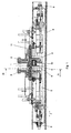
- Fig.1, einen Vertikalschnitt durch eine Weiche mit einem Weichenantrieb,
- Fig.2, eine Detailansicht des Weichenantriebes und des Mitnehmers für das bewegliche Herzstück,
- Fig.3, einen Schnitt gemäß der Linie III-III der Fig.1 und
- Fig.4, eine Detailansicht der verstellbaren Lager für die Lagerung des Zylinderkolbenaggregates in der Trogschwelle.
- In Fig.1 ist das bewegliche Herzstück mit 1 bezeichnet und in Anlage an die Flügelschienen 2 bzw. 3 verschiebbar. Sämtliche Bestandteile der Umstell-, Verschluss- und Prüfereinrichtungen sind unterhalb der Gleisebene in einer Trogschwelle 4 angeordnet. Die Umstelleinrichtung 5 ist hierbei von einem Zylinderkolbenaggregat gebildet und ist mittels Lager 6 an der ortsfesten Trogschwelle angelenkt. Wie nachfolgend noch erläutert werden wird, sind die Lager 6 derart beschaffen, dass eine Justierung der Umstellvorrichtung 5 in Schwellenlängsrichtung gemäß dem Doppelpfeil 7 zur Einstellung der Mittenlage des Zylinderkolbenaggregates vorgenommen werden kann. Die Umstellvorrichtung 5 ist mit einem Mitnehmerteil 8 gekoppelt, welcher die Umstellbewegung an das bewegliche Herzstück 1 weitergibt. Die Mitnahme erfolgt hierbei über verstellbare Anschläge 9, welche mit einem Gleitstein 10 zusammenwirken, welcher wiederum mit der Grundplatte 11 des beweglichen Herzstückes 1 verbunden ist. Durch Einstellung eines Leerhubes zwischen den Anschlägen 9 und dem Gleitstein 10 kann der effektive Hub des beweglichen Herzstückes 1 exakt eingestellt werden.
- In Fig.2 sind nun die einzelnen Kupplungs- und Mitnehmerteile vergrößert dargestellt. Es ist ersichtlich, dass der am Zylinderkolbenaggregat schwenkbar abgestützte Mitnehmer 8 von zwei das Zylinderkolbenaggregat 5 umgebenden Hülsen 34 mit Fortsätzen 12 gebildet wird, welche von einer Spindel 13 durchsetzt werden, wobei die Position der Spindel 13 relativ zu den Fortsätzen 12 des Mitnehmers 8 mittels der von dem mit größerem Durchmesser ausgebildeten Bereich 14 der Spindel 13 ausgebildeten Anschlagsschultern fixiert ist. Der mit vergrößertem Durchmesser ausgebildete Bereich 14 der Spindel 13 weist weiters zwei Gewindeabschnitte 15 und 16 auf, welche zueinander entgegengesetzte Gewinderichtungen aufweisen. Eine Verdrehung der Spindel führt nun dazu, dass die auf den Gewindebereichen 15 und 16 gelagerten verdrehgesicherten Anschlagteile 9 in der Art einer Mitnehmermutter gemäß dem Doppelpfeil 17 voneinander weg oder zueinander bewegt werden. Der Mitnehmerteil umfasst nun weiters einen Gleitstein 10, welcher von der Spindel 13 durchsetzt wird und auf dieser zwischen den Anschlägen 9 gleitend bewegbar gelagert ist. Durch Verstellung der Anschläge 9 entsprechend dem Doppelpfeil 17 kann nun der Leerhub a zwischen den Anschlägen 9 und dem Gleitstein 10 eingestellt werden, um den Umstellhub des Zylinderkolbenaggregates 5 auf den jeweils erforderlichen Verstellhub des beweglichen Herzstückes 1 zu reduzieren.
- Der Gleitstein 10 weist weiters einen inneren Teil 18 mit einem Zylinderabschnitt mit der Zylinderachse 19 auf, sodass eine Verschwenkung des Zylinderteiles 18 um die Drehachse 19 relativ zum äußeren Teil 20 des Gleitsteines 10 und damit relativ zum Mitnehmer 8 erfolgen kann. Der Zylinderteil 18 greift in einen Mitnehmerbügel 21 ein, der wiederum mit der Grundplatte 11 des beweglichen Herzstückes 1 verschweißt ist, sodass insgesamt eine Ausgleichsbewegung während der bei der Umstellbewegung des Herzstückes 1 notwendigen Verschwenkung des Herzstückes 1 relativ zur Umstellvorrichtung 5 ermöglicht wird.
- In der Seitenansicht gemäß Fig.3 ist die bügelartige Form des Mitnehmerteiles 21 ersichtlich, wobei erkennbar ist, dass der Gleitstein 10 entsprechend dem Doppelpfeil 22 gleitend in den bügelförmigen Mitnahmeteil 21 bewegbar ist, sodass Längsverschiebungen des beweglichen Herzstückes 1, welche beispielsweise durch thermische Ausdehnungen verursacht werden können, nicht an den Umstellmechanismus weitergegeben werden. Weiters ist ersichtlich, dass die Anschläge 9, d.h. die Mitnehmermutter, an den Hülsen 34 der Mitnehmer drehfest abgestützt sind. Dadurch wird eine Verdrehsicherung der Anschläge 9 relativ zur Spindelverdrehung erreicht und die axiale Verschiebung der Anschläge 9 sichergestellt. Je nach Auf- und Abbewegung entsprechend dem Doppelpfeil 24 und der Verschiebung in Schienenlängsrichtung entsprechend dem Doppelpfeil 22 des beweglichen Herzstückes wird sich eine Positionierung des Mitnehmers 8 zur Achse 23 um den Zentriwinkel α einstellen, sodass keine Kräfte in das Zylinderkolbenaggregat aus diesen Bewegungen eingeleitet werden.
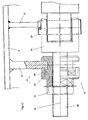
- In Fig.4 ist nun die Lagerung des Zylinderkolbenaggregates 5 an der Trogschwelle 4 näher dargestellt. Das Lager 6 ist hierbei mit einem Gabelkopf 25 versehen, dessen Gabel drehfest und in Richtung der Achse 23 des Zylinderkolbenaggregates 5 verschiebbar abgestützt und über einen Lagerzapfen 26 mit dem hydraulischen Zylinderkolbenaggregat 5 verbunden ist. Die Fixierung der Drehlage des Gabelkopfes 5 erfolgt hierbei dadurch, dass der Gabelkopf 25 an einem von der Trogschwellenseitenwand ausgehenden Steg 27 abgestützt ist. Der Gabelkopf 25 ist mit einer Gabelkopfschraube 28 verbunden, welche eine Stellmutter 29 trägt. Die Verdrehung der Stellmutter 29, deren axiale Lage mittels des mit der Trogschwelle 4 starr verbundenen Anschlages 30 fixiert ist, bewirkt eine axiale Verschiebung des Gabelkopfes 25 entsprechend dem Doppelpfeil 31. Mit Hilfe des Überwurfteiles 32 und der Mutter 33 wird die eingestellte axiale Lage des Gabelkopfes fixiert. Durch diese axiale Verschiebung des Gabelkopfes und damit des Zylinderkolbenaggregates, welche naturgemäß auf beiden Seiten des Zylinderkolbenaggregates in beiden verstellbaren Lagern 6 erfolgen muss, kann die Mittellage des Kolbenhubes exakt eingestellt werden.
Claims (6)
- Weichenantrieb für bewegliche Herzstücke mit wenigstens einem Zylinderkolbenaggregat mit definiertem, voreingestellten Kolbenhub, dadurch gekennzeichnet, dass das Zylinderkolbenaggregat (5) mit in Achsrichtung (31) des Kolbenhubes verstellbaren Lagern (6) verbunden ist, welche mit einer ortsfesten Unterkonstruktion zur Einstellung einer definierten Mittellage des Kolbenhubes und des Mitnehmers für das bewegliche Herzstück (1) verbunden ist und dass der Mitnehmer für das bewegliche Herzstück (1) unter Zwischenschaltung von in Achsrichtung verstellbaren Anschlägen (9) mit dem Zylinderkolbenaggregat (5) gekoppelt ist.
- Weichenantrieb nach Anspruch 1, dadurch gekennzeichnet, dass der Mitnehmer einen Gleitstein (10) aufweist und eine Relativbewegung des Herzstückes (1) in zwei einander kreuzenden, von der Achse des Verstellhubes verschiedenen Achsen ermöglicht.
- Weichenantrieb nach Anspruch 1 oder 2, dadurch gekennzeichnet, dass der Mitnehmer von einer Spindel (13) mit zu beiden Seiten des Mitnehmers verschiedener Gewinderichtung in Richtung des Verstellhubes durchsetzt ist und mit drehfest geführten Muttern (9) mit einem einstellbaren Leerhub zusammenwirkt.
- Weichenantrieb nach Anspruch 1, 2 oder 3, dadurch gekennzeichnet, dass der Mitnehmer um die Achse des zylinderkolbenaggregates (5) schwenkbar angeordnet ist und der Gleitstein (10) des Mitnehmers einen Zapfen- oder Zylinderabschnitt (18) trägt bzw. aufweist, welcher um eine auf die Richtung des Verstellhubes im wesentlichen normal verlaufenden Achse (19) schwenkbar angeordnet ist.
- Weichenantrieb nach einem der Ansprüche 1 bis 4, dadurch gekennzeichnet, dass die in Achsrichtung (31) des Kolbenhubes verstellbaren Lager (6) als Gabelkopf (25) ausgebildet sind, dessen Gabel drehfest und in Achsrichtung (31) verschiebbar abgestützt ist und über einen Lagerzapfen (26) mit dem hydraulischen Zylinderkolbenaggregat (5) verbunden ist und dass mit dem Gabelkopf (25) eine Gabelkopfschraube (28) verbunden ist, welche einen Anschlag (30) durchsetzt und eine Stellmutter (29) trägt, deren Verdrehung eine axiale Verschiebung des Gabelkopfes (25) bewirkt.
- Weichenantrieb nach einem der Ansprüche 1 bis 5, dadurch gekennzeichnet, dass der Anschlag (30) als offener Schlitz einer sich quer zur Schwellenlängsrichtung erstreckenden Wand einer Trogschwelle (4) oder eines ortsfesten Teiles einer Weiche ausgebildet ist.
Priority Applications (2)
| Application Number | Priority Date | Filing Date | Title |
|---|---|---|---|
| AT03735142T ATE335643T1 (de) | 2002-08-13 | 2003-06-16 | Weichenantrieb für bewegliche herze |
| SI200330521T SI1528998T1 (sl) | 2002-08-13 | 2003-06-16 | Kretnicni pogon za premicna srca |
Applications Claiming Priority (3)
| Application Number | Priority Date | Filing Date | Title |
|---|---|---|---|
| AT12282002 | 2002-08-13 | ||
| AT0122802A AT411350B (de) | 2002-08-13 | 2002-08-13 | Weichenantrieb für bewegliche herze |
| PCT/AT2003/000169 WO2004014709A1 (de) | 2002-08-13 | 2003-06-16 | Weichenantrieb für bewegliche herze |
Publications (2)
| Publication Number | Publication Date |
|---|---|
| EP1528998A1 EP1528998A1 (de) | 2005-05-11 |
| EP1528998B1 true EP1528998B1 (de) | 2006-08-09 |
Family
ID=3687511
Family Applications (1)
| Application Number | Title | Priority Date | Filing Date |
|---|---|---|---|
| EP03735142A Expired - Lifetime EP1528998B1 (de) | 2002-08-13 | 2003-06-16 | Weichenantrieb für bewegliche herze |
Country Status (16)
| Country | Link |
|---|---|
| US (1) | US7168663B2 (de) |
| EP (1) | EP1528998B1 (de) |
| CN (1) | CN100465037C (de) |
| AT (1) | AT411350B (de) |
| AU (1) | AU2003237561B2 (de) |
| BR (1) | BR0313463A (de) |
| CA (1) | CA2493999A1 (de) |
| DE (1) | DE50304598D1 (de) |
| DK (1) | DK1528998T3 (de) |
| ES (1) | ES2270048T3 (de) |
| HR (1) | HRP20050236A2 (de) |
| NO (1) | NO20051252L (de) |
| PL (1) | PL201243B1 (de) |
| PT (1) | PT1528998E (de) |
| WO (1) | WO2004014709A1 (de) |
| ZA (1) | ZA200500892B (de) |
Families Citing this family (12)
| Publication number | Priority date | Publication date | Assignee | Title |
|---|---|---|---|---|
| DE10340784B4 (de) * | 2003-09-02 | 2007-04-12 | Thyssenkrupp Gft Gleistechnik Gmbh | Kreuzung oder Weiche |
| ITFI20030296A1 (it) * | 2003-11-19 | 2005-05-20 | Ge Transp Systems S P A | Cassa di manovra per scambi ferroviari |
| US7341226B2 (en) * | 2004-11-17 | 2008-03-11 | General Electric Company | Movable point frog switching assembly |
| ES1072245Y (es) | 2010-04-09 | 2010-09-09 | Amurrio Ferrocarril Y Equipos | Dispositivo de encerrojamiento para corazon de punta movil |
| DE102012017982A1 (de) * | 2012-09-12 | 2014-03-13 | Schwihag Ag | Herzstückrollvorrichtung |
| CZ24854U1 (cs) * | 2012-12-13 | 2013-01-21 | DT-VÝHYBKÁRNA A STROJÍRNA, a.s. | Dotlacovací zarízení |
| RU2539619C2 (ru) * | 2013-02-14 | 2015-01-20 | Открытое Акционерное Общество "Российские Железные Дороги" | Комплект устройств для закрепления и контроля положения остряков и подвижных сердечников крестовин стрелок |
| US9290192B2 (en) | 2013-12-11 | 2016-03-22 | Voestalpine Nortrak Inc. | Spring wing controller |
| US9932054B2 (en) * | 2016-02-19 | 2018-04-03 | Progress Rail Services Corporation | Double point derail switch |
| CN107601271B (zh) * | 2017-11-02 | 2024-04-09 | 扬州市神力吊具制造有限公司 | 一种辙叉吊具 |
| CN110396875B (zh) * | 2018-04-25 | 2021-02-23 | 比亚迪股份有限公司 | 一种道岔梁驱动装置、道岔和轨道 |
| CN114108401A (zh) * | 2020-08-31 | 2022-03-01 | 董军军 | 一种道岔转辙部分及护轨部分专用改道器 |
Family Cites Families (14)
| Publication number | Priority date | Publication date | Assignee | Title |
|---|---|---|---|---|
| US1446743A (en) * | 1923-02-27 | Switch-locking mechanism | ||
| US1253439A (en) * | 1915-10-09 | 1918-01-15 | Thomas George Stiles | Switch mechanism. |
| US1744604A (en) * | 1928-06-09 | 1930-01-21 | Thomas J Arledge | Automatic switch-latch mechanism |
| DE2002025C3 (de) | 1970-01-17 | 1975-06-12 | Butzbacher Weichenbau Gmbh, 6308 Butzbach | Herzstück mit beweglicher Spitze |
| US3521053A (en) * | 1968-06-10 | 1970-07-21 | Pintsch Bamag Ag | Crossing frogs for rails of railroad track and the like |
| IT1213950B (it) * | 1987-12-16 | 1990-01-05 | Sasib Spa | Dispositivo universale di fermascambiatura esterna per deviatoi ferroviari |
| DE69104431T2 (de) * | 1990-07-19 | 1995-04-20 | Siliani Angiolo Spa | Vorrichtung zum Betreiben der Weichenzungen einer Eisenbahnweiche. |
| IT1242226B (it) * | 1990-10-10 | 1994-03-03 | Sasib Spa | Dispositivo di manovra per deviatoi ferroviari, in particolare per linee ad alta velocita' |
| DE4305228A1 (de) | 1993-02-19 | 1994-08-25 | Butzbacher Weichenbau Gmbh | Herzstück |
| AT403462B (de) * | 1995-05-03 | 1998-02-25 | Vae Ag | Einrichtung zum umstellen von weichen |
| CN1151951A (zh) * | 1995-12-13 | 1997-06-18 | 西门子公司 | 转辙器传动装置 |
| IT1298019B1 (it) * | 1997-10-22 | 1999-12-20 | Sasib Railway Spa | Cassa di manovra per scambi ferroviari, ferrotranviari, o simili. |
| CN2401422Y (zh) * | 1999-12-10 | 2000-10-18 | 北京铁路局太原电务器材厂 | 轨枕式道岔转辙机 |
| AT411047B (de) | 2001-01-11 | 2003-09-25 | Vae Eisenbahnsysteme Gmbh | Einrichtung zum verriegeln der endlagen von beweglichen weichenteilen |
-
2002
- 2002-08-13 AT AT0122802A patent/AT411350B/de not_active IP Right Cessation
-
2003
- 2003-06-16 ES ES03735142T patent/ES2270048T3/es not_active Expired - Lifetime
- 2003-06-16 AU AU2003237561A patent/AU2003237561B2/en not_active Ceased
- 2003-06-16 WO PCT/AT2003/000169 patent/WO2004014709A1/de not_active Ceased
- 2003-06-16 DE DE50304598T patent/DE50304598D1/de not_active Expired - Lifetime
- 2003-06-16 PT PT03735142T patent/PT1528998E/pt unknown
- 2003-06-16 PL PL373579A patent/PL201243B1/pl not_active IP Right Cessation
- 2003-06-16 US US10/523,564 patent/US7168663B2/en not_active Expired - Fee Related
- 2003-06-16 DK DK03735142T patent/DK1528998T3/da active
- 2003-06-16 BR BR0313463-6A patent/BR0313463A/pt not_active IP Right Cessation
- 2003-06-16 EP EP03735142A patent/EP1528998B1/de not_active Expired - Lifetime
- 2003-06-16 HR HR20050236A patent/HRP20050236A2/hr not_active Application Discontinuation
- 2003-06-16 CN CNB038193817A patent/CN100465037C/zh not_active Expired - Fee Related
- 2003-06-16 CA CA002493999A patent/CA2493999A1/en not_active Abandoned
-
2005
- 2005-01-31 ZA ZA200500892A patent/ZA200500892B/xx unknown
- 2005-03-10 NO NO20051252A patent/NO20051252L/no not_active Application Discontinuation
Also Published As
| Publication number | Publication date |
|---|---|
| DE50304598D1 (de) | 2006-09-21 |
| PT1528998E (pt) | 2006-12-29 |
| ZA200500892B (en) | 2006-07-26 |
| ES2270048T3 (es) | 2007-04-01 |
| AU2003237561B2 (en) | 2009-10-01 |
| CN1675097A (zh) | 2005-09-28 |
| PL201243B1 (pl) | 2009-03-31 |
| DK1528998T3 (da) | 2006-12-11 |
| AT411350B (de) | 2003-12-29 |
| HRP20050236A2 (en) | 2005-10-31 |
| BR0313463A (pt) | 2005-07-05 |
| CN100465037C (zh) | 2009-03-04 |
| PL373579A1 (en) | 2005-09-05 |
| NO20051252L (no) | 2005-03-10 |
| US20050269459A1 (en) | 2005-12-08 |
| EP1528998A1 (de) | 2005-05-11 |
| US7168663B2 (en) | 2007-01-30 |
| ATA12282002A (de) | 2003-05-15 |
| CA2493999A1 (en) | 2004-02-19 |
| WO2004014709A1 (de) | 2004-02-19 |
| AU2003237561A1 (en) | 2004-02-25 |
Similar Documents
| Publication | Publication Date | Title |
|---|---|---|
| EP1528998B1 (de) | Weichenantrieb für bewegliche herze | |
| DE69813275T2 (de) | Schaltkasten für eisenbahn, strassenbahnweichen oder dergleichen vom sogenannten englischen typ | |
| DE19502105C2 (de) | Verschlußvorrichtung für Weichenzungen | |
| AT502042B1 (de) | Vorrichtung zur endlagenprüfung von beweglichen teilen einer schienenweiche | |
| AT391500B (de) | Umstellvorrichtung fuer bewegliche teile einer schienenweiche | |
| EP1159183B1 (de) | Weichenverschluss für weichenzungen | |
| AT411351B (de) | Endlagenprüfeinrichtung für bewegliche weichenteile | |
| DE19612091A1 (de) | Hubsäule | |
| EP1538264B1 (de) | Herzstück | |
| DE60123203T4 (de) | Weichenstellvorrichtung für Eisenbahnweichen oder dergleichen, mit einer auffahrbahren Widerstandsvorrichtung zum Entgegenwirken des Auffahrens der Weichen | |
| EP0315619B1 (de) | Umstellvorrichtung für schwenkbare Schienen oder bewegliche Herzstücke im Kreuzungsbereich einer Weiche | |
| DE2612819A1 (de) | Eckumlenkung fuer fensterbeschlaege | |
| EP0679789B1 (de) | Dreh-Beschlag oder Dreh-Kipp-Beschlag von Fenstern, Türen oder dergleichen | |
| EP2893081B1 (de) | Weiche für schienen | |
| EP0165229B1 (de) | Vorrichtung zur Sicherung der Lage der Zungenschienen von Gleisweichen | |
| EP0212484A2 (de) | Türschliesser | |
| EP0624506B1 (de) | Halterungsanordnung für querbewegliche Bremsklotzeinheiten an Schienenfahrzeuge | |
| EP1493645A1 (de) | Einrichtung zum Umstellen von Weichen | |
| DE10212979B4 (de) | Endlagenprüfvorrichtung für eine Weiche | |
| DE19732477C2 (de) | Vorrichtung für den Ausgleich von Längsbewegungen von Weichenzungen an Stell-oder Überwachungseinrichtungen | |
| DE4112928C2 (de) | Klammerverschluß für Weichen | |
| DE3334161C2 (de) | ||
| DE10030325C2 (de) | Gleitstück | |
| DE20300816U1 (de) | Weiche für eine Förderanlage | |
| EP2812226B1 (de) | Einrichtung zum umstellen einer schienenweiche |
Legal Events
| Date | Code | Title | Description |
|---|---|---|---|
| PUAI | Public reference made under article 153(3) epc to a published international application that has entered the european phase |
Free format text: ORIGINAL CODE: 0009012 |
|
| 17P | Request for examination filed |
Effective date: 20050202 |
|
| AK | Designated contracting states |
Kind code of ref document: A1 Designated state(s): AT BE BG CH CY CZ DE DK EE ES FI FR GB GR HU IE IT LI LU MC NL PT RO SE SI SK TR |
|
| AX | Request for extension of the european patent |
Extension state: AL LT LV MK |
|
| RAX | Requested extension states of the european patent have changed |
Extension state: LT Payment date: 20050202 Extension state: LV Payment date: 20050202 |
|
| GRAP | Despatch of communication of intention to grant a patent |
Free format text: ORIGINAL CODE: EPIDOSNIGR1 |
|
| GRAS | Grant fee paid |
Free format text: ORIGINAL CODE: EPIDOSNIGR3 |
|
| GRAA | (expected) grant |
Free format text: ORIGINAL CODE: 0009210 |
|
| AK | Designated contracting states |
Kind code of ref document: B1 Designated state(s): AT BE BG CH CY CZ DE DK EE ES FI FR GB GR HU IE IT LI LU MC NL PT RO SE SI SK TR |
|
| AX | Request for extension of the european patent |
Extension state: LT LV |
|
| PG25 | Lapsed in a contracting state [announced via postgrant information from national office to epo] |
Ref country code: IT Free format text: LAPSE BECAUSE OF FAILURE TO SUBMIT A TRANSLATION OF THE DESCRIPTION OR TO PAY THE FEE WITHIN THE PRESCRIBED TIME-LIMIT;WARNING: LAPSES OF ITALIAN PATENTS WITH EFFECTIVE DATE BEFORE 2007 MAY HAVE OCCURRED AT ANY TIME BEFORE 2007. THE CORRECT EFFECTIVE DATE MAY BE DIFFERENT FROM THE ONE RECORDED. Effective date: 20060809 Ref country code: IE Free format text: LAPSE BECAUSE OF FAILURE TO SUBMIT A TRANSLATION OF THE DESCRIPTION OR TO PAY THE FEE WITHIN THE PRESCRIBED TIME-LIMIT Effective date: 20060809 |
|
| REG | Reference to a national code |
Ref country code: GB Ref legal event code: FG4D Free format text: NOT ENGLISH |
|
| REG | Reference to a national code |
Ref country code: CH Ref legal event code: EP |
|
| REG | Reference to a national code |
Ref country code: IE Ref legal event code: FG4D Free format text: LANGUAGE OF EP DOCUMENT: GERMAN |
|
| REF | Corresponds to: |
Ref document number: 50304598 Country of ref document: DE Date of ref document: 20060921 Kind code of ref document: P |
|
| GBT | Gb: translation of ep patent filed (gb section 77(6)(a)/1977) |
Effective date: 20061009 |
|
| REG | Reference to a national code |
Ref country code: RO Ref legal event code: EPE |
|
| REG | Reference to a national code |
Ref country code: SE Ref legal event code: TRGR |
|
| REG | Reference to a national code |
Ref country code: CH Ref legal event code: NV Representative=s name: PPS POLYVALENT PATENT SERVICE AG |
|
| REG | Reference to a national code |
Ref country code: DK Ref legal event code: T3 |
|
| REG | Reference to a national code |
Ref country code: EE Ref legal event code: FG4A Ref document number: E000646 Country of ref document: EE Effective date: 20061101 |
|
| REG | Reference to a national code |
Ref country code: GR Ref legal event code: EP Ref document number: 20060403877 Country of ref document: GR |
|
| REG | Reference to a national code |
Ref country code: HU Ref legal event code: AG4A Ref document number: E000866 Country of ref document: HU |
|
| REG | Reference to a national code |
Ref country code: PT Ref legal event code: SC4A Free format text: AVAILABILITY OF NATIONAL TRANSLATION Effective date: 20061103 |
|
| ET | Fr: translation filed | ||
| REG | Reference to a national code |
Ref country code: IE Ref legal event code: FD4D |
|
| REG | Reference to a national code |
Ref country code: ES Ref legal event code: FG2A Ref document number: 2270048 Country of ref document: ES Kind code of ref document: T3 |
|
| PLBE | No opposition filed within time limit |
Free format text: ORIGINAL CODE: 0009261 |
|
| STAA | Information on the status of an ep patent application or granted ep patent |
Free format text: STATUS: NO OPPOSITION FILED WITHIN TIME LIMIT |
|
| 26N | No opposition filed |
Effective date: 20070510 |
|
| PG25 | Lapsed in a contracting state [announced via postgrant information from national office to epo] |
Ref country code: MC Free format text: LAPSE BECAUSE OF NON-PAYMENT OF DUE FEES Effective date: 20070630 |
|
| PGFP | Annual fee paid to national office [announced via postgrant information from national office to epo] |
Ref country code: DK Payment date: 20080610 Year of fee payment: 6 Ref country code: HU Payment date: 20080609 Year of fee payment: 6 Ref country code: LU Payment date: 20080613 Year of fee payment: 6 |
|
| PGFP | Annual fee paid to national office [announced via postgrant information from national office to epo] |
Ref country code: SK Payment date: 20080611 Year of fee payment: 6 |
|
| PGFP | Annual fee paid to national office [announced via postgrant information from national office to epo] |
Ref country code: FI Payment date: 20080613 Year of fee payment: 6 Ref country code: SI Payment date: 20080613 Year of fee payment: 6 Ref country code: BG Payment date: 20080618 Year of fee payment: 6 |
|
| PGFP | Annual fee paid to national office [announced via postgrant information from national office to epo] |
Ref country code: NL Payment date: 20080618 Year of fee payment: 6 |
|
| PGFP | Annual fee paid to national office [announced via postgrant information from national office to epo] |
Ref country code: BE Payment date: 20080728 Year of fee payment: 6 |
|
| PGFP | Annual fee paid to national office [announced via postgrant information from national office to epo] |
Ref country code: GR Payment date: 20080620 Year of fee payment: 6 |
|
| PG25 | Lapsed in a contracting state [announced via postgrant information from national office to epo] |
Ref country code: CY Free format text: LAPSE BECAUSE OF FAILURE TO SUBMIT A TRANSLATION OF THE DESCRIPTION OR TO PAY THE FEE WITHIN THE PRESCRIBED TIME-LIMIT Effective date: 20060809 |
|
| BERE | Be: lapsed |
Owner name: *VAE G.M.B.H. Effective date: 20090630 Owner name: *VAE EISENBAHNSYSTEME G.M.B.H. Effective date: 20090630 |
|
| PG25 | Lapsed in a contracting state [announced via postgrant information from national office to epo] |
Ref country code: FI Free format text: LAPSE BECAUSE OF NON-PAYMENT OF DUE FEES Effective date: 20090616 |
|
| REG | Reference to a national code |
Ref country code: DK Ref legal event code: EBP |
|
| NLV4 | Nl: lapsed or anulled due to non-payment of the annual fee |
Effective date: 20100101 |
|
| REG | Reference to a national code |
Ref country code: SK Ref legal event code: MM4A Ref document number: E 1146 Country of ref document: SK Effective date: 20090616 |
|
| REG | Reference to a national code |
Ref country code: SI Ref legal event code: KO00 Effective date: 20100205 |
|
| PG25 | Lapsed in a contracting state [announced via postgrant information from national office to epo] |
Ref country code: HU Free format text: LAPSE BECAUSE OF NON-PAYMENT OF DUE FEES Effective date: 20090617 |
|
| PG25 | Lapsed in a contracting state [announced via postgrant information from national office to epo] |
Ref country code: SI Free format text: LAPSE BECAUSE OF NON-PAYMENT OF DUE FEES Effective date: 20090617 Ref country code: SK Free format text: LAPSE BECAUSE OF NON-PAYMENT OF DUE FEES Effective date: 20090616 |
|
| PG25 | Lapsed in a contracting state [announced via postgrant information from national office to epo] |
Ref country code: BE Free format text: LAPSE BECAUSE OF NON-PAYMENT OF DUE FEES Effective date: 20090630 |
|
| PG25 | Lapsed in a contracting state [announced via postgrant information from national office to epo] |
Ref country code: BG Free format text: FAILURE TO ELECT DOMICILE IN THE NATIONAL COUNTRY Effective date: 20091231 Ref country code: DK Free format text: LAPSE BECAUSE OF NON-PAYMENT OF DUE FEES Effective date: 20090630 Ref country code: NL Free format text: LAPSE BECAUSE OF NON-PAYMENT OF DUE FEES Effective date: 20100101 |
|
| PG25 | Lapsed in a contracting state [announced via postgrant information from national office to epo] |
Ref country code: GR Free format text: LAPSE BECAUSE OF NON-PAYMENT OF DUE FEES Effective date: 20100107 |
|
| PG25 | Lapsed in a contracting state [announced via postgrant information from national office to epo] |
Ref country code: LU Free format text: LAPSE BECAUSE OF NON-PAYMENT OF DUE FEES Effective date: 20090616 |
|
| PGFP | Annual fee paid to national office [announced via postgrant information from national office to epo] |
Ref country code: ES Payment date: 20110624 Year of fee payment: 9 Ref country code: FR Payment date: 20110630 Year of fee payment: 9 Ref country code: CZ Payment date: 20110613 Year of fee payment: 9 Ref country code: CH Payment date: 20110623 Year of fee payment: 9 Ref country code: PT Payment date: 20110613 Year of fee payment: 9 Ref country code: TR Payment date: 20110602 Year of fee payment: 9 Ref country code: SE Payment date: 20110613 Year of fee payment: 9 |
|
| PGFP | Annual fee paid to national office [announced via postgrant information from national office to epo] |
Ref country code: EE Payment date: 20110614 Year of fee payment: 9 Ref country code: AT Payment date: 20110613 Year of fee payment: 9 Ref country code: GB Payment date: 20110620 Year of fee payment: 9 Ref country code: RO Payment date: 20110530 Year of fee payment: 9 |
|
| PGFP | Annual fee paid to national office [announced via postgrant information from national office to epo] |
Ref country code: DE Payment date: 20110622 Year of fee payment: 9 Ref country code: IT Payment date: 20110623 Year of fee payment: 9 |
|
| REG | Reference to a national code |
Ref country code: CH Ref legal event code: PFA Owner name: VAE EISENBAHNSYSTEME GMBH Free format text: VAE EISENBAHNSYSTEME GMBH#ALPINESTRASSE 1#8740 ZELTWEG (AT) $ VAE GMBH#ROTENTURMSTRASSE 5-9#1010 WIEN (AT) -TRANSFER TO- VAE EISENBAHNSYSTEME GMBH#ALPINESTRASSE 1#8740 ZELTWEG (AT) $ VAE GMBH#ROTENTURMSTRASSE 5-9#1010 WIEN (AT) |
|
| REG | Reference to a national code |
Ref country code: PT Ref legal event code: MM4A Free format text: LAPSE DUE TO NON-PAYMENT OF FEES Effective date: 20121217 |
|
| REG | Reference to a national code |
Ref country code: LT Ref legal event code: MM9D Effective date: 20120616 |
|
| REG | Reference to a national code |
Ref country code: SE Ref legal event code: EUG |
|
| PG25 | Lapsed in a contracting state [announced via postgrant information from national office to epo] |
Ref country code: CZ Free format text: LAPSE BECAUSE OF NON-PAYMENT OF DUE FEES Effective date: 20120616 |
|
| REG | Reference to a national code |
Ref country code: CH Ref legal event code: PL |
|
| REG | Reference to a national code |
Ref country code: CH Ref legal event code: PL Ref country code: EE Ref legal event code: MM4A Ref document number: E000646 Country of ref document: EE Effective date: 20120630 Ref country code: AT Ref legal event code: MM01 Ref document number: 335643 Country of ref document: AT Kind code of ref document: T Effective date: 20120616 |
|
| GBPC | Gb: european patent ceased through non-payment of renewal fee |
Effective date: 20120616 |
|
| PG25 | Lapsed in a contracting state [announced via postgrant information from national office to epo] |
Ref country code: IT Free format text: LAPSE BECAUSE OF NON-PAYMENT OF DUE FEES Effective date: 20120616 Ref country code: PT Free format text: LAPSE BECAUSE OF NON-PAYMENT OF DUE FEES Effective date: 20121217 Ref country code: SE Free format text: LAPSE BECAUSE OF NON-PAYMENT OF DUE FEES Effective date: 20120617 |
|
| REG | Reference to a national code |
Ref country code: FR Ref legal event code: ST Effective date: 20130228 |
|
| REG | Reference to a national code |
Ref country code: DE Ref legal event code: R119 Ref document number: 50304598 Country of ref document: DE Effective date: 20130101 |
|
| PG25 | Lapsed in a contracting state [announced via postgrant information from national office to epo] |
Ref country code: EE Free format text: LAPSE BECAUSE OF NON-PAYMENT OF DUE FEES Effective date: 20120630 Ref country code: FR Free format text: LAPSE BECAUSE OF NON-PAYMENT OF DUE FEES Effective date: 20120702 Ref country code: RO Free format text: LAPSE BECAUSE OF NON-PAYMENT OF DUE FEES Effective date: 20120616 Ref country code: DE Free format text: LAPSE BECAUSE OF NON-PAYMENT OF DUE FEES Effective date: 20130101 Ref country code: GB Free format text: LAPSE BECAUSE OF NON-PAYMENT OF DUE FEES Effective date: 20120616 Ref country code: CH Free format text: LAPSE BECAUSE OF NON-PAYMENT OF DUE FEES Effective date: 20120630 Ref country code: LI Free format text: LAPSE BECAUSE OF NON-PAYMENT OF DUE FEES Effective date: 20120630 |
|
| PG25 | Lapsed in a contracting state [announced via postgrant information from national office to epo] |
Ref country code: AT Free format text: LAPSE BECAUSE OF NON-PAYMENT OF DUE FEES Effective date: 20120616 |
|
| REG | Reference to a national code |
Ref country code: ES Ref legal event code: FD2A Effective date: 20131023 |
|
| PG25 | Lapsed in a contracting state [announced via postgrant information from national office to epo] |
Ref country code: TR Free format text: LAPSE BECAUSE OF NON-PAYMENT OF DUE FEES Effective date: 20120616 Ref country code: ES Free format text: LAPSE BECAUSE OF NON-PAYMENT OF DUE FEES Effective date: 20120617 |