EP1528837B1 - Matrice plastique chauffable électriquement - Google Patents
Matrice plastique chauffable électriquement Download PDFInfo
- Publication number
- EP1528837B1 EP1528837B1 EP04022246A EP04022246A EP1528837B1 EP 1528837 B1 EP1528837 B1 EP 1528837B1 EP 04022246 A EP04022246 A EP 04022246A EP 04022246 A EP04022246 A EP 04022246A EP 1528837 B1 EP1528837 B1 EP 1528837B1
- Authority
- EP
- European Patent Office
- Prior art keywords
- contact
- structure according
- honeycomb
- electrically conductive
- contact means
- Prior art date
- Legal status (The legal status is an assumption and is not a legal conclusion. Google has not performed a legal analysis and makes no representation as to the accuracy of the status listed.)
- Not-in-force
Links
- 239000004033 plastic Substances 0.000 title claims abstract description 14
- 229920003023 plastic Polymers 0.000 title claims abstract description 14
- 239000011159 matrix material Substances 0.000 title description 4
- 239000006260 foam Substances 0.000 claims abstract description 31
- 239000010410 layer Substances 0.000 claims description 36
- 229910052751 metal Inorganic materials 0.000 claims description 25
- 239000002184 metal Substances 0.000 claims description 25
- OKTJSMMVPCPJKN-UHFFFAOYSA-N Carbon Chemical compound [C] OKTJSMMVPCPJKN-UHFFFAOYSA-N 0.000 claims description 20
- 238000000576 coating method Methods 0.000 claims description 12
- 239000011248 coating agent Substances 0.000 claims description 10
- 239000000463 material Substances 0.000 claims description 10
- 125000006850 spacer group Chemical group 0.000 claims description 9
- 239000000853 adhesive Substances 0.000 claims description 8
- 230000001070 adhesive effect Effects 0.000 claims description 8
- 238000009413 insulation Methods 0.000 claims description 6
- 239000002245 particle Substances 0.000 claims description 6
- 238000004026 adhesive bonding Methods 0.000 claims description 5
- 238000004544 sputter deposition Methods 0.000 claims description 5
- BQCADISMDOOEFD-UHFFFAOYSA-N Silver Chemical compound [Ag] BQCADISMDOOEFD-UHFFFAOYSA-N 0.000 claims description 4
- 239000012790 adhesive layer Substances 0.000 claims description 4
- 229910052709 silver Inorganic materials 0.000 claims description 4
- 239000004332 silver Substances 0.000 claims description 4
- 210000001520 comb Anatomy 0.000 claims description 3
- 238000009713 electroplating Methods 0.000 claims description 3
- 239000004922 lacquer Substances 0.000 claims description 3
- 208000007101 Muscle Cramp Diseases 0.000 claims description 2
- 238000010849 ion bombardment Methods 0.000 claims description 2
- 238000005240 physical vapour deposition Methods 0.000 claims description 2
- 238000001179 sorption measurement Methods 0.000 claims 3
- 231100000167 toxic agent Toxicity 0.000 claims 1
- 239000003440 toxic substance Substances 0.000 claims 1
- 238000009834 vaporization Methods 0.000 claims 1
- 239000012530 fluid Substances 0.000 abstract description 6
- 239000011888 foil Substances 0.000 description 52
- 241000264877 Hippospongia communis Species 0.000 description 51
- 238000010438 heat treatment Methods 0.000 description 44
- 239000003570 air Substances 0.000 description 24
- 230000000694 effects Effects 0.000 description 8
- 229910010293 ceramic material Inorganic materials 0.000 description 4
- 239000003344 environmental pollutant Substances 0.000 description 4
- 238000004519 manufacturing process Methods 0.000 description 4
- 239000002985 plastic film Substances 0.000 description 4
- 229920006255 plastic film Polymers 0.000 description 4
- 231100000719 pollutant Toxicity 0.000 description 4
- 239000000919 ceramic Substances 0.000 description 3
- 238000000034 method Methods 0.000 description 3
- RYGMFSIKBFXOCR-UHFFFAOYSA-N Copper Chemical compound [Cu] RYGMFSIKBFXOCR-UHFFFAOYSA-N 0.000 description 2
- 239000003463 adsorbent Substances 0.000 description 2
- 239000012080 ambient air Substances 0.000 description 2
- 239000004020 conductor Substances 0.000 description 2
- 229910052802 copper Inorganic materials 0.000 description 2
- 239000010949 copper Substances 0.000 description 2
- 238000007598 dipping method Methods 0.000 description 2
- 238000005485 electric heating Methods 0.000 description 2
- 239000006261 foam material Substances 0.000 description 2
- 239000000203 mixture Substances 0.000 description 2
- 239000003973 paint Substances 0.000 description 2
- 239000000843 powder Substances 0.000 description 2
- 239000000126 substance Substances 0.000 description 2
- 208000031872 Body Remains Diseases 0.000 description 1
- 229910021536 Zeolite Inorganic materials 0.000 description 1
- 239000011324 bead Substances 0.000 description 1
- 238000005452 bending Methods 0.000 description 1
- 238000010276 construction Methods 0.000 description 1
- HNPSIPDUKPIQMN-UHFFFAOYSA-N dioxosilane;oxo(oxoalumanyloxy)alumane Chemical compound O=[Si]=O.O=[Al]O[Al]=O HNPSIPDUKPIQMN-UHFFFAOYSA-N 0.000 description 1
- 238000009826 distribution Methods 0.000 description 1
- 238000010292 electrical insulation Methods 0.000 description 1
- 230000005611 electricity Effects 0.000 description 1
- 238000005516 engineering process Methods 0.000 description 1
- 238000001914 filtration Methods 0.000 description 1
- 239000010439 graphite Substances 0.000 description 1
- 229910002804 graphite Inorganic materials 0.000 description 1
- 238000009434 installation Methods 0.000 description 1
- 229910021645 metal ion Inorganic materials 0.000 description 1
- 239000012811 non-conductive material Substances 0.000 description 1
- 239000002984 plastic foam Substances 0.000 description 1
- 229920000642 polymer Polymers 0.000 description 1
- 239000011148 porous material Substances 0.000 description 1
- 238000002360 preparation method Methods 0.000 description 1
- 238000005245 sintering Methods 0.000 description 1
- 230000000087 stabilizing effect Effects 0.000 description 1
- 238000009423 ventilation Methods 0.000 description 1
- XLYOFNOQVPJJNP-UHFFFAOYSA-N water Substances O XLYOFNOQVPJJNP-UHFFFAOYSA-N 0.000 description 1
- 238000004804 winding Methods 0.000 description 1
- 239000010457 zeolite Substances 0.000 description 1
Images


Classifications
-
- H—ELECTRICITY
- H05—ELECTRIC TECHNIQUES NOT OTHERWISE PROVIDED FOR
- H05B—ELECTRIC HEATING; ELECTRIC LIGHT SOURCES NOT OTHERWISE PROVIDED FOR; CIRCUIT ARRANGEMENTS FOR ELECTRIC LIGHT SOURCES, IN GENERAL
- H05B3/00—Ohmic-resistance heating
- H05B3/10—Heating elements characterised by the composition or nature of the materials or by the arrangement of the conductor
- H05B3/12—Heating elements characterised by the composition or nature of the materials or by the arrangement of the conductor characterised by the composition or nature of the conductive material
- H05B3/14—Heating elements characterised by the composition or nature of the materials or by the arrangement of the conductor characterised by the composition or nature of the conductive material the material being non-metallic
- H05B3/146—Conductive polymers, e.g. polyethylene, thermoplastics
-
- H—ELECTRICITY
- H01—ELECTRIC ELEMENTS
- H01C—RESISTORS
- H01C7/00—Non-adjustable resistors formed as one or more layers or coatings; Non-adjustable resistors made from powdered conducting material or powdered semi-conducting material with or without insulating material
- H01C7/02—Non-adjustable resistors formed as one or more layers or coatings; Non-adjustable resistors made from powdered conducting material or powdered semi-conducting material with or without insulating material having positive temperature coefficient
-
- H—ELECTRICITY
- H05—ELECTRIC TECHNIQUES NOT OTHERWISE PROVIDED FOR
- H05B—ELECTRIC HEATING; ELECTRIC LIGHT SOURCES NOT OTHERWISE PROVIDED FOR; CIRCUIT ARRANGEMENTS FOR ELECTRIC LIGHT SOURCES, IN GENERAL
- H05B2203/00—Aspects relating to Ohmic resistive heating covered by group H05B3/00
- H05B2203/02—Heaters using heating elements having a positive temperature coefficient
-
- H—ELECTRICITY
- H05—ELECTRIC TECHNIQUES NOT OTHERWISE PROVIDED FOR
- H05B—ELECTRIC HEATING; ELECTRIC LIGHT SOURCES NOT OTHERWISE PROVIDED FOR; CIRCUIT ARRANGEMENTS FOR ELECTRIC LIGHT SOURCES, IN GENERAL
- H05B2203/00—Aspects relating to Ohmic resistive heating covered by group H05B3/00
- H05B2203/022—Heaters specially adapted for heating gaseous material
- H05B2203/024—Heaters using beehive flow through structures
Definitions
- the invention relates to an electrically heatable structure made of an electrically conductive plastic according to the preamble of claim 1.
- Such independent heaters consist of a register of heating elements, which are overflowed by ambient air, which is then passed into the vehicle interior.
- the heating of the air via electrically heated PTC elements, which increase their resistance with increasing temperature and are thus self-regulating.
- the PTC elements which are made of a ceramic material, are arranged in heating elements and release their heat to the ambient air via corrugated fins, ie secondary heat exchange surfaces.
- Integrated systems were created by the DE-A 44 33 814 , the DE-A 198 35 225 or the EP-B 0 707 434 known. Also these integrated electric booster heaters use secondary heat exchange surfaces to release the heat generated by the PTC elements into the air. This requires a corresponding design and circuit complexity.
- a resistance heating element for a vehicle air conditioner having a honeycomb body made of a positive temperature coefficient resistance material is known.
- the honeycomb body is formed from at least two honeycombs, which are electrically connected in parallel and arranged in the same flow directions of the heat carrier in series, wherein the resistance heating element is formed from a piezoceramic material having a positive temperature coefficient.
- an electrical resistance heating element with a honeycomb body made of a resistive material having a positive temperature coefficient wherein the channels to be heated by a medium to be heated channels have metallized walls which are contacted from the end faces of the honeycomb body forth by a Stirn vommetallmaschine checkerboard alternately electrically.
- the honeycomb body is formed of a ceramic material.
- a resistor for a fluid heater formed of a ceramic resistor material having a positive temperature coefficient is known.
- a body which is formed of a ceramic electrical resistance material having a positive temperature coefficient.
- organic foam material is provided with a ceramic material powder. The organic foam is then heated to position the ceramic material powder on the walls of the passageways in the foam. Subsequently, the foam material is burned off, so that after sintering, only the ceramic structure of the body remains.
- the first solution according to the invention relates to a honeycomb structure, the second solution to a foam structure and the third solution to a structure produced from an endless film by corrugation, folding or winding.
- All three structures have in common the advantage that they provide a large number of channels, in particular air channels, which are separated from one another by thin walls in a given space or a predetermined cross section.
- These channel walls are made of an electrically conductive plastic, in particular with PTC effect are directly heated by the electric heating with direct or alternating current and thus can deliver this heat directly to a fluid, especially air.
- the channel walls be it in the honeycomb or foam structure or in the film structure thus form primary surfaces for heat exchange or heat transfer. Secondary heat exchange surfaces are thus eliminated. All three structures can be produced in terms of production technology simply and in large quantities, ie inexpensively.
- the structures comprise contact means by which the plastic structure is connected to the electrical terminals.
- electrically conductive combs with prongs are provided for the honeycomb structure as contact means, which are provided on two connection sides of the structure in the channel openings, i. H. the honeycombs are introduced and thus make electrical contact with the honeycomb structure.
- This type of contacting has the advantage that the honeycomb structure does not need to be separately prepared and processed.
- connection foils in particular metal foils.
- the honeycomb structure has contact surfaces, on which metal layers are applied, for.
- sputtering d. H. by "bombardment" with appropriate metal ions. This eliminates one operation, namely the gluing.
- the honeycomb structure is contacted frontally, d. H. on the sides with the honeycomb openings.
- These end faces of the honeycomb structure are provided with a metallic coating, for. B. by dipping, by electroplating or chemical methods.
- the contacting of the end faces on the front and the back of a honeycomb element can be effected by electrically conductive frame, which contact the metallic coating.
- brackets are provided for the contacting of the foam structure, which engage in the edge regions of the foam structure and thus produce the electrical contact. This represents a particularly simple type of contacting, especially since the foam structure does not have to be specially prepared here.
- the foam structure is formed as a block with opposing contact surfaces, on which metal foils are glued to produce the electrical contact, with an electrically conductive adhesive such.
- FIG. 1 A block diagram illustrating an omega-shaped fold of the endless foil.
- FIG. 1 A block diagram illustrating an omega-shaped fold of the endless foil.
- FIG. 1 A block diagram illustrating an omega-shaped fold of the endless foil.
- FIG. 1 A block diagram illustrating an omega-shaped fold of the endless foil.
- FIG. 1 Advantageous in an omega-shaped fold of the endless foil are spacer knobs, which are mutually pronounced before folding from the endless foil according to a predetermined pattern and engage after folding in such a way that the foil sections kept at a distance and thus air ducts are formed.
- an elastic metal fleece is provided for contacting a film structure, which rests on the wave crests or folding edges of the film structure and produces an electrically conductive connection to the electrical connections.
- a further advantageous embodiment of the invention provides for contacting a marginal metallic coating of the endless film, d. H. before it is folded or curled.
- the contacting of the film structure takes place here so frontally, so that the current flows in the longitudinal direction of the fluid or air channels.
- the endless film is on its top and bottom each with an electrically conductive contact layer covered so that the current passes across the thickness of the film.
- the contact layers can advantageously be covered with insulation layers to the outside.
- an advantageous development provides that activated carbon particles are applied to the insulation layer or layers, so that the structure can be used as a filter, in particular an odor filter. When heating the structure due to current flow, the filter is desorbed, that is, the particle-laden filter is cleaned and gets its full filtering action back.
- the contact layers on the top and bottom of the films are contacted by laterally arranged staples or extending through in the longitudinal direction of the foil connecting wires.
- the film coated on both sides can advantageously be wound up into a spiral, which is connected on its two end faces to conductive frame crosses, so-called supply frames. Each frame forms an electrical connection, wherein the contacting takes place at the interfaces between the spiral and the frame cross.
- the abovementioned structures can be used as carrier structures (carrier matrices) for desorbable filters. These are adsorbed on the surface of the structure, z. B. applied activated carbon particles.
- the fixation of the adsorbent or activated carbon grains by means of an electrically insulating adhesive, paint or a film.
- non-conductive adsorbents such as zeolite or the like, can also be applied directly to the foam structure in the warm and especially soft state.
- the filter, z. B. an odor filter for the interior of a motor vehicle can thus be regenerated at any time.
- the plastic of the structure that is optionally the matrix, additionally crosslinked. This is particularly preferably achieved in the production by means of high-energy ⁇ -rays.
- all structures are covered with an electrical insulation layer.
- electrically conductive fluids eg. As water or a water-glycol mixture can be heated by the various structural forms.
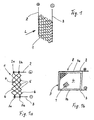
- Fig. 1 shows schematically a section of a honeycomb structure 1, which is made of an electrically conductive plastic with PTC effect.
- the preparation is preferably carried out by known methods, ie by adhering films together, which are then pulled apart to form the honeycomb channels. By this manufacturing method, relatively thin wall thicknesses can be realized for the honeycomb structure.
- the honeycomb structure 1 is connected on opposite sides to a positive electrical connection rail 2 and to a negative electrical connection rail 3.
- FIG. 1 a shows a section of the honeycomb structure 1 according to FIG. 1 in a view from the front, that is to say with a view of an end face 4, which is represented by a plurality is formed by honeycomb openings 5.
- the honeycomb openings 5, shown here in simplified form as rectangles or squares, are formed by zig-zag.
- Foils 6 are formed, which extend from the positive rail 2 to the negative rail 3.
- the individual foils 6 are electrically contacted at the connection points 2a, 2b or 3a, 3b, ie the structure 1 is constructed from a multiplicity of parallel-connected conductors 6, which are traversed by current in parallel. This results in a calculable resistance and at a given voltage at the electrical terminals 2, 3, a certain heating of the structure 1.
- the temperature of the films 6 and the channel walls can be about 100 degrees Celsius.
- the resistance of the films 6 increases with increasing temperature, so that upon reaching a predetermined maximum temperature no further heating takes place. The heating is thus self-regulating.
- FIG. 1b shows the honeycomb structure 1 in a closed frame 7, wherein two mutually opposite frame strips 7a, 7b form the electrical connections 2, 3.
- a honeycomb element 8 can be used as auxiliary heating in motor vehicles for heating the indoor air.
- Another application which will be discussed in more detail later, is the use of the heatable honeycomb structure 1 as a carrier matrix for a filter, which can be desorbed by the heating.
- Fig. 2 shows a further basic embodiment of the invention, a foam structure 9, which is constructed of electrically conductive plastic foam, also with PTC effect and air-permeable pores. Trained as a cuboid block foam structure 9 is traversed in the direction of the arrow L of air and has opposite sides on contact surfaces 10, 11, which are connected to electrical terminals 2, 3. The foam structure 9 is thus - in relation to the illustration in Fig. 2 - in the vertical direction through which current flows, wherein a heating the structure occurs, which has a heating of the air flowing through it.
- FIG. 2 a shows the foam structure 9 inserted into a frame 12, which is connected to a support grid 13 for stabilizing the foam structure 9.
- the frame 12 is connected via the contact surfaces 10, 11 with the electrical terminals 2, 3.
- FIG. 3 shows a section of the honeycomb structure 1, which is contacted by a comb 14, which is connected to the electrical connection 2.
- the comb 14 has two staggered rows of tines 15, which are inserted into the honeycomb openings 5. Due to a slight interference fit of the tines 15 in the honeycomb 5 results in a sufficient contact.
- Fig. 3a shows the comb 14 with the tines 15 as a single part.
- Fig. 3b shows the assembly of the comb 14 with the structure 1, wherein on the opposite side of the comb 14, a holding plate 16 is arranged, which is jammed with the protruding ends of the prongs 15.
- Another comb which is not shown in Fig. 3b, is attached to the lower end of the structure 1, not shown, so that the structure 1 is traversed from top to bottom of current.
- Fig. 3c shows another embodiment of the contacting of the structure 1 with two ridges 17, 18 which are inserted from opposite sides into the structure 1 and wedge each other with their teeth, ie hold frictionally.
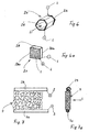
- FIG. 4 shows an approximately cube-shaped honeycomb structure 1 with an end face 4, which contains the honeycomb openings 5.
- conductive connecting foils 19, 20, preferably metal foils are adhesively bonded, ie by means of adhesive layers 21, 22, e.g. B. a silver adhesive.
- the metal foils 19, 20 are connected to the electrical terminals 2, 3, so that the cube 1 uniformly in the vertical direction, related on the representation in the drawing, is traversed by current, ie transverse to the longitudinal direction of the flow channels. 5
- the structural block 1 has an upper contact surface 23, on which a metal layer, not shown, is applied, preferably by sputtering, ie ion bombardment, z. B. with copper.
- a metal layer not shown
- the lower surface opposite the upper contact surface 23 is provided with a metal layer. The current for heating the structure 1 is uniformly introduced into the block via these metal layers.
- Fig. 6 shows a single honeycomb 24, the front and rear end face of a metallic coating 25, 26 has.
- a metallic coating 25, 26 can be applied by dipping, electroplating, by chemical means, by sputtering or gluing.
- the coatings 25, 26 are connected to the electrical terminals 2, 3, so that the honeycomb 24 is traversed in the air flow direction L from the stream.
- Fig. 6a shows a honeycomb element 27 with a frame 28 which, isolated from each other, has a front frame part 28a and a rear frame part 28b.
- the honeycomb structure 1 is, corresponding to the individual honeycomb 24 in FIG. 6, provided on both the front and the rear end face completely with the metallic coating 25, 26, which in each case in conductive connection with the front or rear frame 28 a, 28 b stands.
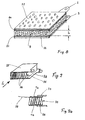
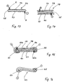
- Fig. 7 shows the contacting of the foam structure 9 according to Fig. 2.
- the foam structure 9 is formed as a plate here, which is at its upper and lower narrow side by means of brackets 29, 30 connected to the electrical terminals 2, 3.
- Fig. 7a shows a side view with the brackets 29, 30, which engage in the upper and lower narrow side of the foam structure 9 and thus the make electrical contact.
- the foam structure 9 is thus traversed transversely to the air flow direction L from the stream.
- Fig. 8 shows a further possibility of contacting the foam structure 9, which is formed here as a horizontal plate with a bottom and a top as contact surfaces. Electrically conductive metal foils 32, 33, which are connected to the electrical terminals 2, 3, are applied to these contact surfaces by means of electrically conductive adhesive layers 30, 31. The current flow through the foam structure thus takes place here over the shortest dimension of the plate-shaped foam structure 9, ie over the height h.
- FIG. 9 shows a so-called film structure 35, ie a matrix produced from an endless film by folding.
- film air channels 36 are formed, which are traversed by air in the direction of the arrow L. Due to the triangular fold 35 contact surfaces are formed on the top and bottom of the film structure, on which metal foils 37, 38 are glued to the contact.
- Fig. 9a shows a detail of the structure 35 with an endless foil 39.
- the contact surfaces of the film structure 35 are coated with an electrically conductive adhesive or paint, for. B. a Silberleitkleber 40 coated, via which an electrically conductive adhesive bond with the metal foils 37, 38 is produced.
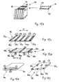
- FIG. 10 shows a further embodiment of a film structure 41, which is produced from an endless foil 42 by folding.
- the structure 41 has planar, mutually parallel channel walls 41 a and omega-shaped folds 41 b, which lie against each other and form a contact surface 41 c to the outside.
- the flat channel walls 41 a are held by Diestanznoppen 42 a at a distance.
- 41 a air channels 43 are formed between the channel walls, which are traversed by air (or other medium) in the direction of the arrow L.
- Fig. 10a shows a piece of continuous film 42 ', which consists of an electrically conductive plastic with PTC effect, immediately before the fold, ie still stretched.
- Two frusto-conical spacer knobs 42a ' are alternately formed downwards from the foil 42' and then two likewise frustoconical spacer knobs 42a ", etc.
- bending regions 41b' are marked which correspond to the finished omega profiles 41b of the structure 41 in FIG.
- FIG. 10 b shows the film structure 41 in a schematic section through the spacer knobs 42 a, wherein it becomes clear that the individual frustoconical spacer knobs 42 a engage in one another in a force-locking manner.
- electrically conductive layers 44 are applied, which are connected to the electrical terminals, not shown here.
- FIG. 11 shows a further embodiment of a film structure 45, which in turn is produced from an endless plastic film by folding.
- the film structure 45 consists of a folded layer, the top and bottom contact an elastic metal fleece 46, 47.
- the film structure 45 with the two metal webs 46, 47 is received in a closed frame 48, from which the two electrical connections are led out 2.3.
- the flow of current thus takes place here via the two metal fleeces 46, 47, which consist of a large number of fine wires and which, owing to their elasticity, cause a distortion of the structure within the frame 48.
- Fig. 12 shows a piece of endless foil 49, the longitudinal extent of which extends in the direction of the center line m.
- the film 49 has two edge regions 49a, 49b, on each of which in the longitudinal direction m extending strips 50, 51 of a metallic coating are applied.
- FIG. 12 a shows a film structure 52, which is produced by corrugation of the edge-coated film 49.
- air channels 52a are formed, which are traversed by air or other medium in the direction of the arrow L.
- the corrugated film structure 52 is received in a frame (not shown in full) 53, which is made of a non-conductive material.
- the current is supplied here via the slightly outwardly projecting coated edge strips 50, 51, which are connected to the electrical terminals 2, 3.
- the current flows through the structure 52 in the direction of the channels 52a and in the direction of the arrow L.
- FIG. 12 b shows a somewhat modified film structure 80, in which a contact material in accumulated form is applied to the end-side edge regions 81, 82.
- a lid 83 has two contact rails 84, 85, which are placed on the film structure 80 and the edge-side contact areas 81, 82.
- the two contact rails 84, 85 form the main distribution for the power supply and discharge.
- Fig. 12c shows an endless foil 86 with a one-sided multiple contact.
- contact strips 87a to 87e are arranged, running in the longitudinal direction and with different polarity, z. B. in the form of metallic coatings.
- the electrical resistance is reduced transversely to the longitudinal direction of the film 86, ie in the direction of the double arrow Z.
- Fig. 12d shows a modified embodiment of an endless film 88, with a Mehrfachrome ist on the top 88a and the bottom 88b.
- On top 88a are three contact strips 89a, 89b, 89c negative polarity and on the bottom 88b are two staggered contact strips (shown in phantom) 89d, 89e arranged.
- Even with this form of Mehrfachrome ist results in a similar effect as in the embodiment of FIG. 12c.
- Fig. 12e shows an endless foil 90 with triple contacting and an insulating layer 91, which in particular with electrically conductive fluids, for. B. a water-glycol mixture is used.
- Fig. 12f shows a modified endless foil 92, in which contact strips 93a, 93b, 93c are stored, which on top of the film 92 at three locations 94a, 94b, 94c for making a main contact by local FreiMlen or are exposed by recesses in the film production.
- FIG. 13 shows a further embodiment of a plastic film, ie a so-called heating foil 54.
- the latter consists of an electrically conductive plastic film 55, preferably with PTC effect and is on its upper side with a highly electrically conductive contact layer 56 and on its underside with an electric well-conductive contact layer 57 covered.
- the contact layers 56, 57 are each connected to the electrical terminals 2, 3.
- FIG. 14 shows a modified heating foil 58 which, in addition to the heating foil 54 according to FIG. 13, is additionally provided with an upper and a lower insulating layer 59, 60.
- the electrical connections 2, 3 penetrate the insulation layers 59, 60 and contact the contact layers 56, 57.
- the electrically highly conductive contact layers 55, 56 can be made of graphite, copper, another metal or even a self-conducting plastic.
- the application of the contact layers can be done for example by sputtering, PVD or other known methods.
- a similar heating foil - however for Schuman and Kraftschitzmaschine GmbH - is in the DE-A 199 39 174 described.
- the heating foil 58 can - which is not shown here - activated carbon particles, eg. B. be applied in the form of beads, z. B. by gluing.
- a film with activated carbon can then be used as a carrier film or as a support structure for odor or pollutant filter for motor vehicles. This results in the advantage that these filters can be heated due to the heating foil and thus are desorbable. The loaded with pollutants activated carbon particles are thus "cleaned” or regenerated by these pollutants are discharged by heating.
- Fig. 15 shows the possibility of contacting the heating foil 58 described above, which here by two laterally arranged, the film 58 embracing, approximately semicircular formed staples 61, 62 takes place.
- the staples 61, 62 each have a contact tip 61 a and 62 a, which the penetrate outer insulating layers 59, 60 and the contact layers 56, 57 contact.
- the staples 61, 62 are connected to the electrical terminals 2, 3, not shown.
- FIG. 16 shows a further embodiment of a heating foil 63, which is similar to the above heating foil 58.
- the contact layers on the top and the bottom are here connected to connection wires 64, 65 (shown in cross section), which lead to the electrical terminals 2, 3, not shown.
- FIG. 16 a shows a corrugated film structure 66, which is formed from the heating foil 63.
- the edge-dashed lines mark the position of the connecting wires 64, 65th
- the heating foils 54, 58, 63 described above have in common that the current flows transversely through the thickness of the central plastic film 55, i. H. This results in an extremely short conductor path, which on the one hand a fairly uniform current flow and on the other hand, a relatively strong heating can be achieved.
- the heating foils are also usable for a surface heating, d. H. as surface heating elements.
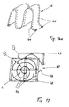
- Fig. 17 shows a spiral-shaped film structure 67, in which the above-mentioned heating foil 58 wound spirally while maintaining a distance a and in the direction of the arrow L of air or other medium can be flowed through.
- On the inflow and the outflow side of the spiral structure 67 are electrically conductive frame in the form of a window cross, so-called feed frame 68, 69 are arranged, which are frontally welded to the heating foil 58, that are electrically connected, namely at the intersection points 70 of Spiral with the "window cross".
- the feed frames 68, 69 are connected to the electrical terminals.
- Embodiments of an electric heating can be used not only DC but also AC generally.
Landscapes
- Engineering & Computer Science (AREA)
- Microelectronics & Electronic Packaging (AREA)
- Ceramic Engineering (AREA)
- Physics & Mathematics (AREA)
- Electromagnetism (AREA)
- Resistance Heating (AREA)
- Manufacture Of Porous Articles, And Recovery And Treatment Of Waste Products (AREA)
- Laminated Bodies (AREA)
- Exhaust Gas After Treatment (AREA)
- Developing Agents For Electrophotography (AREA)
- Superconductors And Manufacturing Methods Therefor (AREA)
- Heating, Cooling, Or Curing Plastics Or The Like In General (AREA)
Claims (23)
- Structure pouvant être chauffée électriquement, constituée d'une matière plastique conductrice d'électricité ayant des propriétés CTP, la structure présentant des canaux pouvant être traversés par de l'air et des connexions électriques (2, 3),
caractérisée en ce que la structure est configurée sous forme de structure en nid d'abeille (1), et il est prévu des moyens de contact reliés aux connexions électriques (2, 3) et configurés sous forme de peignes (14, 17, 18) avec des dents (15), insérés dans les canaux (5) de la structure en nid d'abeille (1). - Structure pouvant être chauffée électriquement, constituée d'une matière plastique conductrice d'électricité ayant des propriétés CTP, la structure présentant des canaux pouvant être traversés par de l'air et des connexions électriques (2, 3),
caractérisée en ce que la structure est configurée sous forme de structure en mousse (9), et il est prévu des moyens de contact reliés aux connexions électriques (2, 3) et la structure en mousse (9) est configurée avec des surfaces de contact se faisant face et les moyens de contact sont configurés sous forme de feuilles métalliques (32, 33) collées sur les surfaces de contact. - Structure pouvant être chauffée électriquement, constituée d'une matière plastique conductrice d'électricité ayant des propriétés CTP, la structure présentant des canaux pouvant être traversés par de l'air et des connexions électriques (2, 3),
caractérisée en ce que la structure est formée par une feuille sans fin (39, 42, 49, 58, 63) ondulée ou pliée ou enroulée, et il est prévu des moyens de contact reliés aux connexions électriques (2, 3) et la feuille pliée forme une structure (45) avec des surfaces de contact se faisant face et en ce que
les moyens de contact sont configurés sous forme de rembourrage métallique élastique (46, 47) reposant sur les surfaces de contact. - Structure selon la revendication 1,
caractérisée en ce que la structure en nid d'abeille (1) est configurée sous forme de bloc rectangulaire ou cubique avec des surfaces de contact et les moyens de contact sont configurés sous forme de feuilles de connexion électriquement conductrices, en particulier des feuilles métalliques (19, 20), collées sur les surfaces de contact. - Structure selon la revendication 1,
caractérisée en ce que la structure en nid d'abeille (1) présente des surfaces de contact (23) se faisant face et en ce que
les moyens de contact sont configurés sous forme de couches métalliques appliquées directement sur les surfaces de contact (23), en particulier par pulvérisation cathodique, dépôt physique en phase vapeur, évaporation à arc électrique ou galvanisation. - Structure selon la revendication 1,
caractérisée en ce que les canaux de la structure en nid d'abeille (1) présentent des ouvertures d'entrée et de sortie (5) en forme de nid d'abeille, qui forment des surfaces frontales (4) côté entrée et sortie, et en ce que
les surfaces frontales (4) présentent un revêtement métallique (25, 26) en tant que moyens de contact. - Structure selon la revendication 2,
caractérisée en ce que la structure en mousse (9) est configurée sous forme de plaque avec des côtés minces se faisant face et les moyens de contact sont configurés sous forme de pinces (29, 30), en particulier de pinces métalliques, qui enserrent chacune un côté mince. - Structure selon la revendication 3,
caractérisée en ce que la feuille pliée (39) présente des crêtes ou des plis disposés successivement, qui forment des surfaces de contact se faisant face, et en ce que
les moyens de contact sont configurés sous la forme d'une couche d'adhésif conductrice d'électricité, en particulier sous forme de vernis conducteur en argent (40). - Structure selon la revendication 3,
caractérisée en ce que la feuille pliée (42) présente des plis (41b) en forme d'oméga disposés successivement sur des côtés se faisant face et formant des surfaces de contact (41c) pour les moyens de contact. - Structure selon la revendication 9,
caractérisée en ce qu'entre les plis (41b) en forme d'oméga sont disposées des parois de canal (41a) écartées les unes des autres, à partir desquelles sont formés des tenons d'écartement (42a). - Structure selon la revendication 3,
caractérisée en ce que les moyens de contact sont configurés sous forme de bandes latérales (50, 51) à revêtement métallique s'étendant dans la direction longitudinale m de la feuille sans fin (49). - Structure selon la revendication 11,
caractérisée en ce que la feuille sans fin (49) est disposée sous forme de couche ondulée ou pliée (52) dans un cadre (53) non conducteur. - Structure selon la revendication 3,
caractérisée en ce que la feuille sans fin (55) présente une face supérieure et une face inférieure, et
les moyens de contact sont configurés sous la forme d'une couche de contact (56, 57) bonne conductrice d'électricité sur la face supérieure et inférieure. - Structure selon la revendication 13,
caractérisée en ce que des couches isolantes (59, 60) sont appliquées sur l'une des couches de contact (56, 57) ou sur les deux. - Structure selon la revendication 14,
caractérisée en ce que des moyens d'adsorption (par exemple des charbons actifs) sont appliqués en particulier par collage sur les couches isolantes (59, 60). - Structure selon la revendication 14,
caractérisée en ce que les couches de contact (56, 57) sont en liaison conductrice d'électricité avec les connexions électriques (2, 3) via des cavaliers (61, 62) disposés sur les bords. - Structure selon la revendication 14,
caractérisée en ce que les couches de contact de la feuille sans fin (63) sont reliées de manière conductrice d'électricité avec des fils de connexion (64, 65) disposés sur les bords. - Structure selon la revendication 13, 14, 16, ou 17,
caractérisée en ce que la feuille sans fin (58) enroulée en forme de spirale est reliée du côté frontal, via des cadres d'amenée (68, 69) conducteurs d'électricité, avec les connexions électriques (2, 3). - Utilisation d'une structure selon la revendication 15 en tant que filtre désodorisant, en particulier filtre anti-odeurs et/ou anti-pollution pour véhicules automobiles.
- Utilisation d'une structure selon l'une des revendications 1 à 18, excepté 15, en tant que structure de support pour un filtre désodorisant, en particulier un filtre à charbons actifs.
- Structure selon l'une des revendications 1 à 11,
caractérisée en ce que la structure est recouverte d'une couche d'isolation électrique. - Structure selon l'une des revendications 1 à 11,
caractérisée en ce qu'à la surface de la structure sont appliqués des moyens d'adsorption, en particulier des grains de charbon actif. - Structure selon la revendication 22,
caractérisée en ce que les moyens d'adsorption sont appliqués au moyen d'un vernis ou d'un adhésif non conducteur d'électricité.
Applications Claiming Priority (2)
| Application Number | Priority Date | Filing Date | Title |
|---|---|---|---|
| DE10351309 | 2003-10-31 | ||
| DE10351309 | 2003-10-31 |
Publications (2)
| Publication Number | Publication Date |
|---|---|
| EP1528837A1 EP1528837A1 (fr) | 2005-05-04 |
| EP1528837B1 true EP1528837B1 (fr) | 2007-12-12 |
Family
ID=34399664
Family Applications (1)
| Application Number | Title | Priority Date | Filing Date |
|---|---|---|---|
| EP04022246A Not-in-force EP1528837B1 (fr) | 2003-10-31 | 2004-09-17 | Matrice plastique chauffable électriquement |
Country Status (3)
| Country | Link |
|---|---|
| EP (1) | EP1528837B1 (fr) |
| AT (1) | ATE381241T1 (fr) |
| DE (2) | DE502004005690D1 (fr) |
Cited By (1)
| Publication number | Priority date | Publication date | Assignee | Title |
|---|---|---|---|---|
| RU2492115C2 (ru) * | 2008-03-14 | 2013-09-10 | Эрсель | Кромка воздухозаборника гондолы турбореактивного двигателя |
Families Citing this family (19)
| Publication number | Priority date | Publication date | Assignee | Title |
|---|---|---|---|---|
| DE102005001385B3 (de) * | 2004-12-22 | 2006-08-24 | Schütz GmbH & Co. KGaA | Elektrisches Luftheizregister |
| ATE446205T1 (de) | 2005-07-28 | 2009-11-15 | Ebm Papst St Georgen Gmbh & Co | Heizaggregat |
| EP1839920B1 (fr) | 2006-03-31 | 2013-02-13 | Behr GmbH & Co. KG | Chauffage électrique pour un système de climatisation d'un véhicule |
| DE202006005745U1 (de) * | 2006-04-06 | 2007-09-27 | Eisele, Michael, Dipl.-Ing. | Heizbare Platte, Bahn, Formteil |
| EP1885159B1 (fr) * | 2006-08-02 | 2014-06-25 | Behr France Rouffach SAS | Ensemble de chauffage électrique, notamment pour véhicule automobile |
| EP1933598B1 (fr) | 2006-12-11 | 2013-11-13 | Behr GmbH & Co. KG | Chauffage ou chauffage supplémentaire électrique, en particulier pour un système de chauffage ou climatisation d'un véhicule |
| EP1935684B1 (fr) * | 2006-12-11 | 2016-05-04 | MAHLE Behr GmbH & Co. KG | Chauffage électrique ou chauffage, en particulier pour un climatiseur ou une installation de chauffage d'un véhicule automobile |
| DE102007001451A1 (de) * | 2007-01-03 | 2008-07-10 | Behr Gmbh & Co. Kg | Heizvorrichtung, insbesondere für ein Kraftfahrzeug |
| DE102007003549A1 (de) * | 2007-01-24 | 2008-07-31 | Valeo Klimasysteme Gmbh | Luftstromerwärmungsvorrichtung mit Heizvlies |
| DE102007062302A1 (de) * | 2007-12-21 | 2009-06-25 | Beru Ag | Heizvorrichtung |
| EP2109347B1 (fr) | 2008-04-11 | 2015-03-11 | Behr GmbH & Co. KG | Dispositif électrique de chauffage destiné à chauffer, en particulier un véhicule automobile |
| RU2483493C2 (ru) * | 2011-04-05 | 2013-05-27 | Александр Николаевич Дубовой | Электронагреватель и способ изготовления сотового нагревательного элемента для него |
| PL398907A1 (pl) * | 2012-04-20 | 2013-10-28 | Formaster Spólka Akcyjna | Oporowy element grzejny |
| DE102012211173A1 (de) * | 2012-06-28 | 2014-01-16 | BSH Bosch und Siemens Hausgeräte GmbH | Haushaltsgerät |
| DE102014111615A1 (de) * | 2014-08-14 | 2016-02-18 | Deutsches Zentrum für Luft- und Raumfahrt e.V. | Durchströmungsvorrichtung und Verfahren zur Herstellung einer Durchströmungsvorrichtung |
| PL234311B1 (pl) | 2014-08-22 | 2020-02-28 | Formaster Spolka Akcyjna | Moduł grzejny |
| DE102017121062A1 (de) * | 2017-05-24 | 2018-11-29 | Webasto SE | Fluidheizgerät, insbesondere Luftheizgerät |
| DE102019204665A1 (de) | 2019-03-06 | 2020-09-10 | Eberspächer catem Hermsdorf GmbH & Co. KG | PTC-Heizelement und eine elektrische Heizvorrichtung |
| DE102022125856A1 (de) | 2022-10-06 | 2024-04-11 | Mahle International Gmbh | Elektrischer Heizer zur Erwärmung eines Fluids |
Citations (2)
| Publication number | Priority date | Publication date | Assignee | Title |
|---|---|---|---|---|
| US5206476A (en) * | 1991-09-30 | 1993-04-27 | General Motors Corporation | Supplementary automobile duct heater |
| DE4213510C1 (en) * | 1992-04-24 | 1993-08-19 | Audi Ag, 8070 Ingolstadt, De | Electric heating arrangement in vehicle heating and ventilation system - is formed by grill located in air outlet and moulded in conductive polymer |
Family Cites Families (4)
| Publication number | Priority date | Publication date | Assignee | Title |
|---|---|---|---|---|
| US4633069A (en) * | 1985-10-21 | 1986-12-30 | Texas Instruments Incorporated | Heat-exchanger |
| US4717813A (en) * | 1986-04-16 | 1988-01-05 | Texas Instruments Incorporated | Multipassage, multiphase electrical heater |
| DE10060301B4 (de) * | 2000-12-05 | 2011-11-17 | Fraunhofer-Gesellschaft zur Förderung der angewandten Forschung e.V. | Elektrisches Widerstandsheizelement mit einem Wabenkörper |
| DE10201262B4 (de) * | 2002-01-15 | 2006-09-07 | Webasto Ag | Widerstandsheizelement |
-
2004
- 2004-09-17 DE DE502004005690T patent/DE502004005690D1/de active Active
- 2004-09-17 EP EP04022246A patent/EP1528837B1/fr not_active Not-in-force
- 2004-09-17 AT AT04022246T patent/ATE381241T1/de not_active IP Right Cessation
- 2004-09-17 DE DE102004045668A patent/DE102004045668A1/de not_active Withdrawn
Patent Citations (2)
| Publication number | Priority date | Publication date | Assignee | Title |
|---|---|---|---|---|
| US5206476A (en) * | 1991-09-30 | 1993-04-27 | General Motors Corporation | Supplementary automobile duct heater |
| DE4213510C1 (en) * | 1992-04-24 | 1993-08-19 | Audi Ag, 8070 Ingolstadt, De | Electric heating arrangement in vehicle heating and ventilation system - is formed by grill located in air outlet and moulded in conductive polymer |
Cited By (1)
| Publication number | Priority date | Publication date | Assignee | Title |
|---|---|---|---|---|
| RU2492115C2 (ru) * | 2008-03-14 | 2013-09-10 | Эрсель | Кромка воздухозаборника гондолы турбореактивного двигателя |
Also Published As
| Publication number | Publication date |
|---|---|
| DE502004005690D1 (de) | 2008-01-24 |
| EP1528837A1 (fr) | 2005-05-04 |
| DE102004045668A1 (de) | 2005-06-30 |
| ATE381241T1 (de) | 2007-12-15 |
Similar Documents
| Publication | Publication Date | Title |
|---|---|---|
| EP1528837B1 (fr) | Matrice plastique chauffable électriquement | |
| DE19805011B4 (de) | Desorbierbares Sorptionsfilter, insbesondere zur Behandlung der einem Fahrzeuginnenraum zuführbaren Luft | |
| DE2625515C2 (de) | Heizvorrichtung für Gase oder Flüssigkeiten | |
| EP1182908B1 (fr) | Elément chauffant PTC employant un adhésif | |
| DE3042420C2 (fr) | ||
| EP0194507B1 (fr) | Elément chauffant pour chauffer des milieux d'écoulement, en particulier sous forme gazeuse | |
| WO1990012951A1 (fr) | Corps electroconducteur a nids d'abeilles comportant des couches intermediaires isolantes supportant des efforts mecaniques | |
| WO2006111240A1 (fr) | Chauffage electrique destine a un systeme de chauffage ou de climatisation d'un vehicule | |
| EP1730996A1 (fr) | Dispositif electrique de chauffage de fluides | |
| EP0097287B1 (fr) | Echangeur de chaleur, spécialement pour systèmes de chauffage et/ou de conditionnement de l'air, préférablement dans les véhicules à moteur | |
| DE102018215398A1 (de) | Elektrische Heizeinrichtung | |
| WO1993012880A1 (fr) | Corps en nids d'abeilles dont la structure interieure est maintenue dans un cadre | |
| EP2145783A2 (fr) | Chauffage de véhicule | |
| DE10012675A1 (de) | Elektrisches Durchfluß-Widerstandsheizelement | |
| EP0369985A1 (fr) | Filtre particulaire régénératif pour gaz d'échappement | |
| DE10201262B4 (de) | Widerstandsheizelement | |
| DE10060301B4 (de) | Elektrisches Widerstandsheizelement mit einem Wabenkörper | |
| DE19804496A1 (de) | Elektrisches Widerstandsheizelement mit einem Wabenkörper aus Widerstandsmaterial mit positivem Temperaturkoeffizienten des Widerstandes (PTC-Widerstand) | |
| DE2854742C2 (de) | Elektrofilter | |
| DE102007020531A1 (de) | Heißlufteinrichtung mit einem im Luftstrom angeordneten Heizelement | |
| EP3827891B1 (fr) | Élément filtrant avec bande de bord conductrice et dispositif de filtrage comprenant un tel élément filtrant | |
| DE102019217453A1 (de) | PTC-Heizzelle | |
| DE19635276C2 (de) | Elektro-keramisches Vielschichtbauelement und Verfahren zu seiner Herstellung | |
| DE102021104263A1 (de) | Heizeinrichtung zur Erwärmung eines Wärmeträgermediums, insbesondere in einem Fahrzeug | |
| DE102017223785A1 (de) | Verfahren zur Herstellung eines wärmeerzeugenden Elementes |
Legal Events
| Date | Code | Title | Description |
|---|---|---|---|
| PUAI | Public reference made under article 153(3) epc to a published international application that has entered the european phase |
Free format text: ORIGINAL CODE: 0009012 |
|
| AK | Designated contracting states |
Kind code of ref document: A1 Designated state(s): AT BE BG CH CY CZ DE DK EE ES FI FR GB GR HU IE IT LI LU MC NL PL PT RO SE SI SK TR |
|
| AX | Request for extension of the european patent |
Extension state: AL HR LT LV MK |
|
| 17P | Request for examination filed |
Effective date: 20051104 |
|
| AKX | Designation fees paid |
Designated state(s): AT BE BG CH CY CZ DE DK EE ES FI FR GB GR HU IE IT LI LU MC NL PL PT RO SE SI SK TR |
|
| 17Q | First examination report despatched |
Effective date: 20051130 |
|
| GRAP | Despatch of communication of intention to grant a patent |
Free format text: ORIGINAL CODE: EPIDOSNIGR1 |
|
| GRAS | Grant fee paid |
Free format text: ORIGINAL CODE: EPIDOSNIGR3 |
|
| GRAA | (expected) grant |
Free format text: ORIGINAL CODE: 0009210 |
|
| AK | Designated contracting states |
Kind code of ref document: B1 Designated state(s): AT BE BG CH CY CZ DE DK EE ES FI FR GB GR HU IE IT LI LU MC NL PL PT RO SE SI SK TR |
|
| REG | Reference to a national code |
Ref country code: GB Ref legal event code: FG4D Free format text: NOT ENGLISH |
|
| REG | Reference to a national code |
Ref country code: CH Ref legal event code: EP |
|
| REG | Reference to a national code |
Ref country code: IE Ref legal event code: FG4D Free format text: LANGUAGE OF EP DOCUMENT: GERMAN |
|
| REF | Corresponds to: |
Ref document number: 502004005690 Country of ref document: DE Date of ref document: 20080124 Kind code of ref document: P |
|
| PG25 | Lapsed in a contracting state [announced via postgrant information from national office to epo] |
Ref country code: SE Free format text: LAPSE BECAUSE OF FAILURE TO SUBMIT A TRANSLATION OF THE DESCRIPTION OR TO PAY THE FEE WITHIN THE PRESCRIBED TIME-LIMIT Effective date: 20080312 |
|
| PG25 | Lapsed in a contracting state [announced via postgrant information from national office to epo] |
Ref country code: NL Free format text: LAPSE BECAUSE OF FAILURE TO SUBMIT A TRANSLATION OF THE DESCRIPTION OR TO PAY THE FEE WITHIN THE PRESCRIBED TIME-LIMIT Effective date: 20071212 Ref country code: PL Free format text: LAPSE BECAUSE OF FAILURE TO SUBMIT A TRANSLATION OF THE DESCRIPTION OR TO PAY THE FEE WITHIN THE PRESCRIBED TIME-LIMIT Effective date: 20071212 Ref country code: SI Free format text: LAPSE BECAUSE OF FAILURE TO SUBMIT A TRANSLATION OF THE DESCRIPTION OR TO PAY THE FEE WITHIN THE PRESCRIBED TIME-LIMIT Effective date: 20071212 Ref country code: FI Free format text: LAPSE BECAUSE OF FAILURE TO SUBMIT A TRANSLATION OF THE DESCRIPTION OR TO PAY THE FEE WITHIN THE PRESCRIBED TIME-LIMIT Effective date: 20071212 |
|
| NLV1 | Nl: lapsed or annulled due to failure to fulfill the requirements of art. 29p and 29m of the patents act | ||
| GBV | Gb: ep patent (uk) treated as always having been void in accordance with gb section 77(7)/1977 [no translation filed] | ||
| PG25 | Lapsed in a contracting state [announced via postgrant information from national office to epo] |
Ref country code: CZ Free format text: LAPSE BECAUSE OF FAILURE TO SUBMIT A TRANSLATION OF THE DESCRIPTION OR TO PAY THE FEE WITHIN THE PRESCRIBED TIME-LIMIT Effective date: 20071212 Ref country code: ES Free format text: LAPSE BECAUSE OF FAILURE TO SUBMIT A TRANSLATION OF THE DESCRIPTION OR TO PAY THE FEE WITHIN THE PRESCRIBED TIME-LIMIT Effective date: 20080323 |
|
| PG25 | Lapsed in a contracting state [announced via postgrant information from national office to epo] |
Ref country code: SK Free format text: LAPSE BECAUSE OF FAILURE TO SUBMIT A TRANSLATION OF THE DESCRIPTION OR TO PAY THE FEE WITHIN THE PRESCRIBED TIME-LIMIT Effective date: 20071212 Ref country code: RO Free format text: LAPSE BECAUSE OF FAILURE TO SUBMIT A TRANSLATION OF THE DESCRIPTION OR TO PAY THE FEE WITHIN THE PRESCRIBED TIME-LIMIT Effective date: 20071212 |
|
| EN | Fr: translation not filed | ||
| PG25 | Lapsed in a contracting state [announced via postgrant information from national office to epo] |
Ref country code: PT Free format text: LAPSE BECAUSE OF FAILURE TO SUBMIT A TRANSLATION OF THE DESCRIPTION OR TO PAY THE FEE WITHIN THE PRESCRIBED TIME-LIMIT Effective date: 20080512 |
|
| REG | Reference to a national code |
Ref country code: IE Ref legal event code: FD4D |
|
| PLBE | No opposition filed within time limit |
Free format text: ORIGINAL CODE: 0009261 |
|
| STAA | Information on the status of an ep patent application or granted ep patent |
Free format text: STATUS: NO OPPOSITION FILED WITHIN TIME LIMIT |
|
| PG25 | Lapsed in a contracting state [announced via postgrant information from national office to epo] |
Ref country code: IE Free format text: LAPSE BECAUSE OF FAILURE TO SUBMIT A TRANSLATION OF THE DESCRIPTION OR TO PAY THE FEE WITHIN THE PRESCRIBED TIME-LIMIT Effective date: 20071212 Ref country code: FR Free format text: LAPSE BECAUSE OF FAILURE TO SUBMIT A TRANSLATION OF THE DESCRIPTION OR TO PAY THE FEE WITHIN THE PRESCRIBED TIME-LIMIT Effective date: 20080926 Ref country code: DK Free format text: LAPSE BECAUSE OF FAILURE TO SUBMIT A TRANSLATION OF THE DESCRIPTION OR TO PAY THE FEE WITHIN THE PRESCRIBED TIME-LIMIT Effective date: 20071212 |
|
| 26N | No opposition filed |
Effective date: 20080915 |
|
| PG25 | Lapsed in a contracting state [announced via postgrant information from national office to epo] |
Ref country code: GB Free format text: LAPSE BECAUSE OF FAILURE TO SUBMIT A TRANSLATION OF THE DESCRIPTION OR TO PAY THE FEE WITHIN THE PRESCRIBED TIME-LIMIT Effective date: 20071212 |
|
| PG25 | Lapsed in a contracting state [announced via postgrant information from national office to epo] |
Ref country code: GR Free format text: LAPSE BECAUSE OF FAILURE TO SUBMIT A TRANSLATION OF THE DESCRIPTION OR TO PAY THE FEE WITHIN THE PRESCRIBED TIME-LIMIT Effective date: 20080313 |
|
| BERE | Be: lapsed |
Owner name: BEHR G.M.B.H. & CO. KG Effective date: 20080930 |
|
| PG25 | Lapsed in a contracting state [announced via postgrant information from national office to epo] |
Ref country code: MC Free format text: LAPSE BECAUSE OF NON-PAYMENT OF DUE FEES Effective date: 20080930 Ref country code: BG Free format text: LAPSE BECAUSE OF FAILURE TO SUBMIT A TRANSLATION OF THE DESCRIPTION OR TO PAY THE FEE WITHIN THE PRESCRIBED TIME-LIMIT Effective date: 20080312 Ref country code: EE Free format text: LAPSE BECAUSE OF FAILURE TO SUBMIT A TRANSLATION OF THE DESCRIPTION OR TO PAY THE FEE WITHIN THE PRESCRIBED TIME-LIMIT Effective date: 20071212 |
|
| REG | Reference to a national code |
Ref country code: CH Ref legal event code: PL |
|
| PG25 | Lapsed in a contracting state [announced via postgrant information from national office to epo] |
Ref country code: CY Free format text: LAPSE BECAUSE OF FAILURE TO SUBMIT A TRANSLATION OF THE DESCRIPTION OR TO PAY THE FEE WITHIN THE PRESCRIBED TIME-LIMIT Effective date: 20071212 Ref country code: BE Free format text: LAPSE BECAUSE OF NON-PAYMENT OF DUE FEES Effective date: 20080930 |
|
| PG25 | Lapsed in a contracting state [announced via postgrant information from national office to epo] |
Ref country code: CH Free format text: LAPSE BECAUSE OF NON-PAYMENT OF DUE FEES Effective date: 20080930 Ref country code: LI Free format text: LAPSE BECAUSE OF NON-PAYMENT OF DUE FEES Effective date: 20080930 Ref country code: AT Free format text: LAPSE BECAUSE OF NON-PAYMENT OF DUE FEES Effective date: 20080917 |
|
| PG25 | Lapsed in a contracting state [announced via postgrant information from national office to epo] |
Ref country code: HU Free format text: LAPSE BECAUSE OF FAILURE TO SUBMIT A TRANSLATION OF THE DESCRIPTION OR TO PAY THE FEE WITHIN THE PRESCRIBED TIME-LIMIT Effective date: 20080613 Ref country code: LU Free format text: LAPSE BECAUSE OF NON-PAYMENT OF DUE FEES Effective date: 20080917 |
|
| PG25 | Lapsed in a contracting state [announced via postgrant information from national office to epo] |
Ref country code: TR Free format text: LAPSE BECAUSE OF FAILURE TO SUBMIT A TRANSLATION OF THE DESCRIPTION OR TO PAY THE FEE WITHIN THE PRESCRIBED TIME-LIMIT Effective date: 20071212 |
|
| PG25 | Lapsed in a contracting state [announced via postgrant information from national office to epo] |
Ref country code: IT Free format text: LAPSE BECAUSE OF NON-PAYMENT OF DUE FEES Effective date: 20080930 |
|
| REG | Reference to a national code |
Ref country code: DE Ref legal event code: R082 Ref document number: 502004005690 Country of ref document: DE Representative=s name: GRAUEL, ANDREAS, DIPL.-PHYS. DR. RER. NAT., DE |
|
| REG | Reference to a national code |
Ref country code: DE Ref legal event code: R081 Ref document number: 502004005690 Country of ref document: DE Owner name: MAHLE INTERNATIONAL GMBH, DE Free format text: FORMER OWNER: BEHR GMBH & CO. KG, 70469 STUTTGART, DE Effective date: 20150323 Ref country code: DE Ref legal event code: R082 Ref document number: 502004005690 Country of ref document: DE Representative=s name: GRAUEL, ANDREAS, DIPL.-PHYS. DR. RER. NAT., DE Effective date: 20150323 |
|
| PGFP | Annual fee paid to national office [announced via postgrant information from national office to epo] |
Ref country code: DE Payment date: 20181001 Year of fee payment: 15 |
|
| REG | Reference to a national code |
Ref country code: DE Ref legal event code: R119 Ref document number: 502004005690 Country of ref document: DE |
|
| PG25 | Lapsed in a contracting state [announced via postgrant information from national office to epo] |
Ref country code: DE Free format text: LAPSE BECAUSE OF NON-PAYMENT OF DUE FEES Effective date: 20200401 |