EP1528159B1 - Rückhaltesystem - Google Patents
Rückhaltesystem Download PDFInfo
- Publication number
- EP1528159B1 EP1528159B1 EP04450182A EP04450182A EP1528159B1 EP 1528159 B1 EP1528159 B1 EP 1528159B1 EP 04450182 A EP04450182 A EP 04450182A EP 04450182 A EP04450182 A EP 04450182A EP 1528159 B1 EP1528159 B1 EP 1528159B1
- Authority
- EP
- European Patent Office
- Prior art keywords
- elements
- dilatation
- concrete
- expansion
- roadway
- Prior art date
- Legal status (The legal status is an assumption and is not a legal conclusion. Google has not performed a legal analysis and makes no representation as to the accuracy of the status listed.)
- Expired - Lifetime
Links
- 230000004888 barrier function Effects 0.000 claims abstract 6
- 238000006073 displacement reaction Methods 0.000 claims description 7
- 239000002184 metal Substances 0.000 claims description 4
- 230000010339 dilation Effects 0.000 description 8
- 238000010276 construction Methods 0.000 description 3
- 230000008878 coupling Effects 0.000 description 3
- 238000010168 coupling process Methods 0.000 description 3
- 238000005859 coupling reaction Methods 0.000 description 3
- 239000012530 fluid Substances 0.000 description 3
- 239000004809 Teflon Substances 0.000 description 1
- 229920006362 Teflon® Polymers 0.000 description 1
- 150000001875 compounds Chemical class 0.000 description 1
- 230000000916 dilatatory effect Effects 0.000 description 1
- 239000004033 plastic Substances 0.000 description 1
- 230000007704 transition Effects 0.000 description 1
Images

Classifications
-
- E—FIXED CONSTRUCTIONS
- E01—CONSTRUCTION OF ROADS, RAILWAYS, OR BRIDGES
- E01D—CONSTRUCTION OF BRIDGES, ELEVATED ROADWAYS OR VIADUCTS; ASSEMBLY OF BRIDGES
- E01D19/00—Structural or constructional details of bridges
- E01D19/10—Railings; Protectors against smoke or gases, e.g. of locomotives; Maintenance travellers; Fastening of pipes or cables to bridges
- E01D19/103—Parapets, railings ; Guard barriers or road-bridges
-
- E—FIXED CONSTRUCTIONS
- E01—CONSTRUCTION OF ROADS, RAILWAYS, OR BRIDGES
- E01F—ADDITIONAL WORK, SUCH AS EQUIPPING ROADS OR THE CONSTRUCTION OF PLATFORMS, HELICOPTER LANDING STAGES, SIGNS, SNOW FENCES, OR THE LIKE
- E01F15/00—Safety arrangements for slowing, redirecting or stopping errant vehicles, e.g. guard posts or bollards; Arrangements for reducing damage to roadside structures due to vehicular impact
- E01F15/02—Continuous barriers extending along roads or between traffic lanes
- E01F15/08—Continuous barriers extending along roads or between traffic lanes essentially made of walls or wall-like elements ; Cable-linked blocks
- E01F15/081—Continuous barriers extending along roads or between traffic lanes essentially made of walls or wall-like elements ; Cable-linked blocks characterised by the use of a specific material
- E01F15/083—Continuous barriers extending along roads or between traffic lanes essentially made of walls or wall-like elements ; Cable-linked blocks characterised by the use of a specific material using concrete
-
- E—FIXED CONSTRUCTIONS
- E01—CONSTRUCTION OF ROADS, RAILWAYS, OR BRIDGES
- E01F—ADDITIONAL WORK, SUCH AS EQUIPPING ROADS OR THE CONSTRUCTION OF PLATFORMS, HELICOPTER LANDING STAGES, SIGNS, SNOW FENCES, OR THE LIKE
- E01F15/00—Safety arrangements for slowing, redirecting or stopping errant vehicles, e.g. guard posts or bollards; Arrangements for reducing damage to roadside structures due to vehicular impact
- E01F15/02—Continuous barriers extending along roads or between traffic lanes
- E01F15/08—Continuous barriers extending along roads or between traffic lanes essentially made of walls or wall-like elements ; Cable-linked blocks
- E01F15/088—Details of element connection
Definitions
- the invention relates to a restraint system according to the preamble of claim 1.
- a restraint system of the type mentioned are provided in the Dilatationsiata, which are essentially formed by a cylinder-piston assembly in which the piston is provided with a small bore, which is an overflow of a fluid from one side of the piston to the other side allow the piston.
- the aim of the invention is to avoid these disadvantages and to propose a restraint system of the type mentioned, in which on the one hand a secure compensation of thermal expansion is ensured even in the curved sections on the one hand in the transverse direction.
- the proposed measures ensure that the elements, eg concrete elements, can move transversely in curve sections in the region of a dilatation joint of a bridge construction by a limited amount. Due to the plain bearings in the region of the dilatation joint closer end portions of these adjacent elements, which are connected to each other via a dilation element, these can rotate together to accommodate transverse displacements. Also, cases are conceivable in which it is sufficient that only one element for receiving transverse displacements can twist. Due to the possibility of a transversal shift of certain elements, they can absorb in curves the transverse movements of the bridge due to thermal expansions with respect to their abutments.
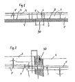
- elements 1 are placed in the region of a dilatation joint 30 between a bridge part with traffic area 2 and an abutment including traffic area.
- the elements e.g. Concrete elements, via a tension band 4 (shown in broken lines), or tensile connections connected to each other.
- a dilatation element 5 is arranged to compensate for thermal expansions in the region of the dilatation joint 30, which is essentially formed by a cylinder-piston element whose spaces separated by the piston are connected to one another via an overflow line which has only a small cross section are such that fluid from one of these two spaces can flow into the other, as for example in a baffle coupling after the DE 100 26 621 A the case is.
- a guide 6 (shown in phantom) is provided, which covers the gap between the two concrete parts 1 connected via the dilatation element 5 and allows only an axial movement of these concrete elements 1 against each other.
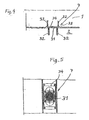
- drawstrings 17 are anchored in the concrete elements 1, 1 ', which are connected to engagement elements 18, which are engaged behind by a substantially T-shaped coupling tension member 19.
- a game 21 is provided between the engagement elements 18 and the Kupplungszugglied 19, or its head portions 20. This allows, together with a compensating gap between the elements 1 and 1 'an angular position of the components 1, 1' to each other, as shown in Fig. 2, but with a high-tensile connection is given.
- the sliding bearings 7 are, as can be seen from FIGS. 4 and 5, formed by metal plates 31, 34 which are connected by means of screws 32 with the concrete part 1, 1 'and the roadway 2. Basically, it is also possible here the metal plates 31, 34 with plastic, e.g. Teflon coat.
- the plate 34 is disposed in a recess 33 of the underside of the concrete part 1, 1 ', wherein the plate 31 projects into this recess 33.
- the limitation of the movement path results from the play in the connection joints 35 between the elements 1 and 1 'and the permissible angle of rotation of the elements 1, which can be determined on the basis of the geometric conditions.
Landscapes
- Engineering & Computer Science (AREA)
- Architecture (AREA)
- Civil Engineering (AREA)
- Structural Engineering (AREA)
- Preparation Of Compounds By Using Micro-Organisms (AREA)
- Input Circuits Of Receivers And Coupling Of Receivers And Audio Equipment (AREA)
- Exchange Systems With Centralized Control (AREA)
- Bridges Or Land Bridges (AREA)
- Road Paving Structures (AREA)
- Actuator (AREA)
Description
- Die Erfindung betrifft ein Rückhaltesystem gemäß dem Oberbegriff des Anspruches 1.
- Durch die
DE 100 26 621 A wurde ein Rückhaltesystem der eingangs erwähnten Art bekannt, bei dem Dilatationselemente vorgesehen sind, die im Wesentlichen durch eine Zylinder-Kolbenanordnung gebildet sind, bei denen der Kolben mit einer kleinen Bohrung versehen ist, die ein Überströmen eines Fluids von einer Seite des Kolbens zur anderen Seite des Kolbens ermöglichen. Dadurch ist eine langsame Bewegung des Kolbens, z.B. aufgrund von Wärmedehnungen der Betonelemente, problemlos möglich, wogegen rasche Änderungen des Kolbens gegenüber dem Zylinder, z.B. aufgrund eines Anpralls eines Fahrzeuges an die Elemente des Rückhaltesystems, verhindert werden. Dadurch ist es möglich Wärmedehnungen aufzunehmen und trotzdem einen stabilen Verbund der Betonelemente sicherzustellen. - Mit solchen Dilatationselementen ist es auf einfache Weise möglich im Bereich von gerade verlaufenden Fahrbahnen die Wärmedehnungen aufzunehmen. Allerdings ist es mit der bekannten Lösung nicht möglich im Bereich von Kurven, in denen Wärmedehnungen auch zu transversalen Verschiebungen führen, diese optimal aufzunehmen.
- Ziel der Erfindung ist es, diese Nachteile zu vermeiden und ein Rückhaltesystem der eingangs erwähnten Art vorzuschlagen, bei dem auch in Kurvenabschnitten einerseits ein sicherer Ausgleich von Wärmedehnungen auch in transversaler Richtung sichergestellt ist.
- Erfindungsgemäß wird dies bei einem Rückhaltesystem der eingangs erwähnten Art durch die kennzeichnenden Merkmale des Anspruches 1 erreicht.
- Durch die vorgeschlagenen Maßnahmen ist sichergestellt, dass sich die Elemente, z.B. Betonelemente, in Kurvenabschnitten im Bereich einer Dilatationsfuge einer Brückenkonstruktion um einen begrenzten Betrag transversal verschieben können. Durch die Gleitlager im Bereich der der Dilatationsfuge näheren Endbereichen der dieser benachbarten Elemente, die über ein Dilatationselement miteinander verbunden sind, können sich diese zur Aufnahme von Querverschiebungen gemeinsam verdrehen. Auch sind Fälle denkbar in welchen es ausreichend ist, dass sich nur ein Element zur Aufnahme von Querverschiebungen verdrehen kann. Durch die Möglichkeit einer transversalen Verschiebung bestimmter Elemente können diese in Kurvenabschnitten die aufgrund von Wärmedehnungen auftretenden transversalen Bewegungen der Brücke gegenüber deren Widerlager aufnehmen. Dabei ist die Wahl der Länge des Dilatationselementes in Verbindung mit einem möglichen Spiel von Bedeutung, das in Kupplungen mit Elementen des Rückhaltesystems vorhanden ist, die an jene Elemente angrenzen, die über ein Dilatationselement miteinander verbunden sind. Durch die Gleitlager, die nahe der Dilatationsfuge angeordnet sind und die Verbindung der an die Dilatationsfuge angrenzenden Elemente über das Dilatationselement, das zwar eine gegenseitige Verschiebung dieser Elemente in deren axialer Richtung ermöglicht, nicht aber eine transversale gegenseitige Verschiebung dieser Elemente wird eine gemeinsame Verdrehung dieser Elemente ermöglicht. Damit können Bewegungen der Brücke durch eine Drehung dieser Element aufgenommen werden
- Durch die Merkmale des Anspruches 2 ergibt sich der Vorteil, das die von der Dilatationsfuge abgekehrten Enden der über ein Dilatationselement verbundenen Elemente im Wesentlichen festgelegt sind und sich daher im Wesentlichen stabile Verhältnisse ergeben
- Um eine einfache Konstruktion zu ermöglichen, ist es vorteilhaft die Merkmale des Anspruches 3 vorzusehen.
- Die Erfindung wird nun anhand der Zeichnung näher erläutert, in der ein Beispiel eines erfindungsgemäßen Rückhaltesystems dargestellt ist. Dabei zeigen:
- Fig. 1 eine Ansicht eines erfindungsgemäßen Rückhaltesystems,
- Fig. 2 eine Draufsicht auf ein erfindungsgemäßes Rückhaltesystem in einem Übergangsbereich von einer Brücke zu einem Widerlager,
- Fig. 3 eine Draufsicht auf eine Verbindung zweier Betonteile,
- Fig. 4 und 5 eine Ansicht und eine Draufsicht auf ein Gleitlager.
- Bei dem erfindungsgemäßen Rückhaltesystem sind im Bereich einer Dilatationsfuge 30 zwischen einem Brückenteil mit Verkehrsfläche 2 und einem Widerlager samt Verkehrsfläche 3 Elemente 1 aufgestellt. Dabei sind die Elemente 1, z.B. Betonelemente, über ein Zugband 4 (strichliert dargestellt), oder zugfeste Verbindungen miteinander verbunden.
- In diesem Zugband 4 ist zum Ausgleich von Wärmedehnungen im Bereich der Dilatationsfuge 30 ein Dilatationselement 5 angeordnet, das im wesentlichen durch ein Zylinder-Kolbenelement gebildet ist, dessen durch den Kolben voneinander getrennte Räume über eine Überströmleitung, die einen nur kleinen Querschnitt aufweist, miteinander verbunden sind, sodass Fluid von einem dieser beiden Räume in den anderen überströmen kann, wie dies z.B. bei einer Leitwandkupplung nach der
DE 100 26 621 A der Fall ist. - Dadurch kann sich der Abstand zwischen den beiden über ein Dilatationselement 5 miteinander verbundenen Betonteile 1 langsam ändern, wie dies z.B. bei Wärmedehnungen der Fall ist. Rasche Änderungen des Abstandes zwischen diesen Betonteilen 1, wie sie sich z.B. bei einem Anprall eines Fahrzeuges an dem Rückhaltesystem ergeben würden, sind jedoch nicht möglich, da das Fluid im Zylinder des Dilatationselementes 5 aufgrund des kleinen Querschnittes der Überströmleitung nur langsam von einer Seite des Kolbens auf die andere Seite des Kolbens überströmen kann.
- Im Bereich einer Dilatationsfuge 30 der Brückenkonstruktion, bzw. des Dilatationselementes 5 ist eine Führung 6 (strichliert dargestellt) vorgesehen, die den Spalt zwischen den beiden über das Dilatationselement 5 verbundenen Betonteilen 1 überdeckt und lediglich eine axiale Bewegung dieser Betonelemente 1 gegeneinander ermöglicht.
- Wie aus der Fig. 2 zu ersehen ist, kommt es im Bereich von Kurven aufgrund von Wärmedehnungen nicht nur zu Längenänderungen sondern auch zu Querverschiebungen des Brückenteiles gegenüber dem Widerlager. Die beiden über das Dilatationselement 5 miteinander verbundenen Betonteile 1 sind im Bereich ihrer der Dilatationsfuge 30 näheren Endbereichen über Gleitlager 7 auf der Verkehrsfläche 2 der Brücke bzw. dem Widerlager 3 abgestützt. Die von der Dilatationsfuge 30 abgekehrten Endbereich der Betonteile 1 sind direkt auf den Verkehrsflächen 2, 3 abgestützt. Diese Abstützung ermöglicht ein gemeinsames Verdrehen der beiden Betonteile 1, die über das Dilatationselement 5 und die Führung 6 miteinander verbunden sind. Dadurch können die in Kurvenabschnitten unvermeidlichen Querbewegungen aufgenommen werden.
- Zu beiden Seiten der über das Dilatationselement 5 miteinander verbundenen Betonteile 1, schließen Betonteile 1' an. Die Betonteile 1 und 1' sind über eine in der Fig. 3 dargestellte Verbindung miteinander verbunden. Dabei sind Zugbänder 17 in den Betonelementen 1, 1' verankert, die mit Eingriffselementen 18 verbunden sind, die von einem im wesentlichen T-förmigen Kupplungs-Zugglied 19 hintergriffen sind. Dabei ist zwischen den Eingriffselementen 18 und dem Kupplungszugglied 19, bzw. dessen Kopfabschnitten 20, ein Spiel 21 vorgesehen. Dies ermöglicht gemeinsam mit einem ausgleichenden Spalt zwischen den Elementen 1 und 1' eine Winkelstellung der Bauteile 1, 1' zueinander, wie sie in der Fig. 2 dargestellt ist., wobei jedoch eine zugfeste Verbindung gegeben ist. Die Verbindung von Betonteilen 1' miteinander erfolgt ebenfalls über Zugglieder 19 und Eingriffselemente 18.
- Bei einer Rückstellung des Brückenteiles gegenüber dem Widerlager kehren die Betonteile 1 wieder in ihre ursprüngliche Lage gegenüber den an diese anschließenden Betonteile 1' zurück, wobei sich die Winkellage W der Betonteile 1 gegenüber den anschließenden Betonteilen 1' wieder auf den ursprünglichen Winkelbetrag einstellt.
- Die Gleitlager 7 sind, wie aus den Fig. 4 und 5 zu ersehen ist, durch Metallplatten 31, 34 gebildet, die mittels Schrauben 32 mit dem Betonteil 1,1' bzw. der Fahrbahn 2 verbunden sind. Grundsätzlich ist es dabei auch möglich die Metallplatten 31, 34 mit Kunststoff, z.B. Teflon zu beschichten.
- Dabei ist die Platte 34 in einer Vertiefung 33 der Unterseite des Betonteils 1, 1' angeordnet, wobei auch die Platte 31 in diese Vertiefung 33 hineinragt. Die Begrenzung des Bewegungsweges ergibt sich aus dem Spiel in der Anschlussfugen 35 zwischen den Elementen 1 und 1' und dem zulässigen Drehwinkel der Elemente 1, der sich aufgrund der geometrischen Verhältnisse ermitteln lässt.
Claims (3)
- Rückhaltesystem mit hintereinander gekoppelten, auf einer Fahrbahn aufgestellten Elementen (1, 1'), insbesondere Betonteile (1, 1'), wobei Elemente (1, 1') miteinander über Dilatationselemente (5) zum Ausgleich von Wärmedehnungen verbunden sind und ein Teil der Elemente (1, 1') über ein Spiel (21) aufweisende Verbindungen (18, 19, 20) miteinander verbunden sind, wobei die Elemente (1, 1') durchgehend miteinander verbunden sind, dadurch gekennzeichnet, dass im Bereich von Dilatationsfugen (30) zwischen einem Brückenteil und einem Widerlager von Brücken die Elemente (1) über Dilatationselemente (5) miteinander verbunden sind, wobei wenigstens ein Element (1) zumindest in einem einer Dilatationsfuge (30) näheren Endbereich auf eine begrenzte Querverschiebung des Elements (1) ermöglichenden Gleitlager (7) abgestützt ist.
- Rückhaltesystem gemäß Anspruch 1, dadurch gekennzeichnet, dass die von der Dilatationsfuge (30) abgekehrten Endbereiche der über das Dilatationselement (5) miteinander verbundenen Elemente (1) direkt auf der Fahrbahn abgestützt sind.
- Rückhaltesystem gemäß Anspruch 1 oder 2, dadurch gekennzeichnet, dass die Gleitlager (7) durch mit der Fahrbahn (2) verbundene Metallplatten (31) und an der Unterseite der Elemente, insbesondere Betonteile (1), angeordnete Metallplatten (34) gebildet sind.
Applications Claiming Priority (2)
| Application Number | Priority Date | Filing Date | Title |
|---|---|---|---|
| AT17252003 | 2003-10-30 | ||
| AT0172503A AT413562B (de) | 2003-10-30 | 2003-10-30 | Rückhaltesystem |
Publications (2)
| Publication Number | Publication Date |
|---|---|
| EP1528159A1 EP1528159A1 (de) | 2005-05-04 |
| EP1528159B1 true EP1528159B1 (de) | 2007-09-05 |
Family
ID=34397362
Family Applications (1)
| Application Number | Title | Priority Date | Filing Date |
|---|---|---|---|
| EP04450182A Expired - Lifetime EP1528159B1 (de) | 2003-10-30 | 2004-09-28 | Rückhaltesystem |
Country Status (3)
| Country | Link |
|---|---|
| EP (1) | EP1528159B1 (de) |
| AT (2) | AT413562B (de) |
| DE (1) | DE502004004862D1 (de) |
Families Citing this family (2)
| Publication number | Priority date | Publication date | Assignee | Title |
|---|---|---|---|---|
| DE202009001131U1 (de) * | 2009-01-29 | 2009-04-02 | Tss Technische Sicherheits-Systeme Gmbh | Übergangskonstruktion zwischen Betonleitwänden |
| DE202009016995U1 (de) * | 2009-12-16 | 2010-04-08 | Tss Technische Sicherheits-Systeme Gmbh | Verbindungselement sowie Verbindungssystem zum Verbinden von Betonleitwänden |
Family Cites Families (5)
| Publication number | Priority date | Publication date | Assignee | Title |
|---|---|---|---|---|
| DE3733685A1 (de) * | 1987-10-05 | 1989-04-20 | Sps Schutzplanken Gmbh | Schutzplankeneinrichtung |
| US5685665A (en) * | 1996-05-09 | 1997-11-11 | Lembo; M. Carl | Roadway barrier and method of installation |
| IT1302420B1 (it) * | 1998-08-05 | 2000-09-05 | Autostrade Concess Const | Dispositivi per la decelerazione calibratra dei veicoli urtantiper barriere di sicurezza a profilo new jersey con ancoraggio |
| DE50003543D1 (de) * | 1999-04-28 | 2003-10-09 | Maba Fertigteilind Gmbh | Leitwand für verkehrswege |
| FR2825728B1 (fr) * | 2001-06-07 | 2003-08-15 | Anciens Etablissements Fremont | Procede pour assurer la continuite de la protection procuree par un muret dans lequel des interruptions sont pratiquees, et ouvrage obtenu |
-
2003
- 2003-10-30 AT AT0172503A patent/AT413562B/de not_active IP Right Cessation
-
2004
- 2004-09-28 EP EP04450182A patent/EP1528159B1/de not_active Expired - Lifetime
- 2004-09-28 AT AT04450182T patent/ATE372420T1/de not_active IP Right Cessation
- 2004-09-28 DE DE502004004862T patent/DE502004004862D1/de not_active Expired - Lifetime
Also Published As
| Publication number | Publication date |
|---|---|
| DE502004004862D1 (de) | 2007-10-18 |
| AT413562B (de) | 2006-03-15 |
| ATA17252003A (de) | 2005-08-15 |
| ATE372420T1 (de) | 2007-09-15 |
| EP1528159A1 (de) | 2005-05-04 |
Similar Documents
| Publication | Publication Date | Title |
|---|---|---|
| WO2008040343A1 (de) | Fahrzeugrückhaltesystem | |
| EP0283808B1 (de) | Duale Weichenanordnung zur gemeinsamen Benutzung durch spurgeführte Schienen- und Magnetfahrzeuge | |
| DE202005007257U1 (de) | Ausbaugestell für eine untertägige Strecke | |
| EP3684976B1 (de) | Zungenvorrichtung | |
| WO2009046695A1 (de) | Fahrzeugrückhaltesystem | |
| EP1528159B1 (de) | Rückhaltesystem | |
| DE202009016995U1 (de) | Verbindungselement sowie Verbindungssystem zum Verbinden von Betonleitwänden | |
| WO2007036239A1 (de) | Fahrzeugrückhaltesysteme zum begrenzen von fahrbahnen | |
| DE10318357B4 (de) | Fahrzeugrückhaltesystem | |
| EP0692574B1 (de) | Fahrbahnübergang | |
| DE19810554C1 (de) | Schutzbrücke für Kabel, Schläuche und dergleichen | |
| EP1138830B1 (de) | Rillenschienenherzstück sowie Verfahren zum Herstellen eines solchen | |
| EP2055840A2 (de) | Leitschwellenstrang | |
| DE202009001131U1 (de) | Übergangskonstruktion zwischen Betonleitwänden | |
| DE2022904A1 (de) | Fahrbahn-Dehnfugenausbildung fuer auf- und abbaubare Stahlbruecken oder Stahlhochstrasse | |
| AT505737B1 (de) | Vorrichtung zum verbinden zweier stumpf stossender bauteile | |
| EP0455207B1 (de) | Relativ zu Flügelschienen verstellbare Herzstückspitze | |
| DE2817533C2 (de) | Schienenanordnung | |
| EP1872836B1 (de) | Schneegleitbrett, insbesondere Ski, mit Unterbrechung in den Profilschienen | |
| DE3227795A1 (de) | Versenkbare leitplanke | |
| EP0758700A1 (de) | Mehrzweckbauteil mit Federelementen | |
| EP2017388B1 (de) | Beton-Wandelement | |
| EP1876300B1 (de) | Schutzplankenstrang aus Stahl | |
| EP2243880A2 (de) | Isolierlasche für einen Isolierstoß | |
| EP2045394A1 (de) | Rillenschienenkreutzungsbereich |
Legal Events
| Date | Code | Title | Description |
|---|---|---|---|
| PUAI | Public reference made under article 153(3) epc to a published international application that has entered the european phase |
Free format text: ORIGINAL CODE: 0009012 |
|
| AK | Designated contracting states |
Kind code of ref document: A1 Designated state(s): AT BE BG CH CY CZ DE DK EE ES FI FR GB GR HU IE IT LI LU MC NL PL PT RO SE SI SK TR |
|
| AX | Request for extension of the european patent |
Extension state: AL HR LT LV MK |
|
| 17P | Request for examination filed |
Effective date: 20051104 |
|
| AKX | Designation fees paid |
Designated state(s): AT BE BG CH CY CZ DE DK EE ES FI FR GB GR HU IE IT LI LU MC NL PL PT RO SE SI SK TR |
|
| GRAP | Despatch of communication of intention to grant a patent |
Free format text: ORIGINAL CODE: EPIDOSNIGR1 |
|
| GRAS | Grant fee paid |
Free format text: ORIGINAL CODE: EPIDOSNIGR3 |
|
| GRAA | (expected) grant |
Free format text: ORIGINAL CODE: 0009210 |
|
| AK | Designated contracting states |
Kind code of ref document: B1 Designated state(s): AT BE BG CH CY CZ DE DK EE ES FI FR GB GR HU IE IT LI LU MC NL PL PT RO SE SI SK TR |
|
| REG | Reference to a national code |
Ref country code: GB Ref legal event code: FG4D Free format text: NOT ENGLISH |
|
| REG | Reference to a national code |
Ref country code: CH Ref legal event code: EP |
|
| REF | Corresponds to: |
Ref document number: 502004004862 Country of ref document: DE Date of ref document: 20071018 Kind code of ref document: P |
|
| REG | Reference to a national code |
Ref country code: IE Ref legal event code: FG4D Free format text: LANGUAGE OF EP DOCUMENT: GERMAN |
|
| GBT | Gb: translation of ep patent filed (gb section 77(6)(a)/1977) |
Effective date: 20071203 |
|
| REG | Reference to a national code |
Ref country code: CH Ref legal event code: NV Representative=s name: BOVARD AG PATENTANWAELTE |
|
| PG25 | Lapsed in a contracting state [announced via postgrant information from national office to epo] |
Ref country code: ES Free format text: LAPSE BECAUSE OF FAILURE TO SUBMIT A TRANSLATION OF THE DESCRIPTION OR TO PAY THE FEE WITHIN THE PRESCRIBED TIME-LIMIT Effective date: 20071216 Ref country code: FI Free format text: LAPSE BECAUSE OF FAILURE TO SUBMIT A TRANSLATION OF THE DESCRIPTION OR TO PAY THE FEE WITHIN THE PRESCRIBED TIME-LIMIT Effective date: 20070905 |
|
| PG25 | Lapsed in a contracting state [announced via postgrant information from national office to epo] |
Ref country code: PL Free format text: LAPSE BECAUSE OF FAILURE TO SUBMIT A TRANSLATION OF THE DESCRIPTION OR TO PAY THE FEE WITHIN THE PRESCRIBED TIME-LIMIT Effective date: 20070905 |
|
| PG25 | Lapsed in a contracting state [announced via postgrant information from national office to epo] |
Ref country code: MC Free format text: LAPSE BECAUSE OF NON-PAYMENT OF DUE FEES Effective date: 20070930 Ref country code: GR Free format text: LAPSE BECAUSE OF FAILURE TO SUBMIT A TRANSLATION OF THE DESCRIPTION OR TO PAY THE FEE WITHIN THE PRESCRIBED TIME-LIMIT Effective date: 20071206 |
|
| EN | Fr: translation not filed | ||
| ET | Fr: translation filed | ||
| REG | Reference to a national code |
Ref country code: FR Ref legal event code: EERR Free format text: CORRECTION DE BOPI 08/18 - BREVETS EUROPEENS DONT LA TRADUCTION N A PAS ETE REMISE A L INPI. IL Y A LIEU DE SUPPRIMER : LA MENTION DE LA NON-REMISE. LA REMISE DE LA TRADUCTION EST PUBLIEE DANS LE PRESENT BOPI. |
|
| PG25 | Lapsed in a contracting state [announced via postgrant information from national office to epo] |
Ref country code: CZ Free format text: LAPSE BECAUSE OF FAILURE TO SUBMIT A TRANSLATION OF THE DESCRIPTION OR TO PAY THE FEE WITHIN THE PRESCRIBED TIME-LIMIT Effective date: 20070905 Ref country code: SK Free format text: LAPSE BECAUSE OF FAILURE TO SUBMIT A TRANSLATION OF THE DESCRIPTION OR TO PAY THE FEE WITHIN THE PRESCRIBED TIME-LIMIT Effective date: 20070905 Ref country code: PT Free format text: LAPSE BECAUSE OF FAILURE TO SUBMIT A TRANSLATION OF THE DESCRIPTION OR TO PAY THE FEE WITHIN THE PRESCRIBED TIME-LIMIT Effective date: 20080206 |
|
| PG25 | Lapsed in a contracting state [announced via postgrant information from national office to epo] |
Ref country code: SE Free format text: LAPSE BECAUSE OF FAILURE TO SUBMIT A TRANSLATION OF THE DESCRIPTION OR TO PAY THE FEE WITHIN THE PRESCRIBED TIME-LIMIT Effective date: 20071205 Ref country code: RO Free format text: LAPSE BECAUSE OF FAILURE TO SUBMIT A TRANSLATION OF THE DESCRIPTION OR TO PAY THE FEE WITHIN THE PRESCRIBED TIME-LIMIT Effective date: 20070905 |
|
| PLBE | No opposition filed within time limit |
Free format text: ORIGINAL CODE: 0009261 |
|
| STAA | Information on the status of an ep patent application or granted ep patent |
Free format text: STATUS: NO OPPOSITION FILED WITHIN TIME LIMIT |
|
| PG25 | Lapsed in a contracting state [announced via postgrant information from national office to epo] |
Ref country code: DK Free format text: LAPSE BECAUSE OF FAILURE TO SUBMIT A TRANSLATION OF THE DESCRIPTION OR TO PAY THE FEE WITHIN THE PRESCRIBED TIME-LIMIT Effective date: 20070905 |
|
| 26N | No opposition filed |
Effective date: 20080606 |
|
| PG25 | Lapsed in a contracting state [announced via postgrant information from national office to epo] |
Ref country code: AT Free format text: LAPSE BECAUSE OF NON-PAYMENT OF DUE FEES Effective date: 20070928 |
|
| PG25 | Lapsed in a contracting state [announced via postgrant information from national office to epo] |
Ref country code: EE Free format text: LAPSE BECAUSE OF FAILURE TO SUBMIT A TRANSLATION OF THE DESCRIPTION OR TO PAY THE FEE WITHIN THE PRESCRIBED TIME-LIMIT Effective date: 20070905 |
|
| PG25 | Lapsed in a contracting state [announced via postgrant information from national office to epo] |
Ref country code: SI Free format text: LAPSE BECAUSE OF FAILURE TO SUBMIT A TRANSLATION OF THE DESCRIPTION OR TO PAY THE FEE WITHIN THE PRESCRIBED TIME-LIMIT Effective date: 20070905 |
|
| PG25 | Lapsed in a contracting state [announced via postgrant information from national office to epo] |
Ref country code: CY Free format text: LAPSE BECAUSE OF FAILURE TO SUBMIT A TRANSLATION OF THE DESCRIPTION OR TO PAY THE FEE WITHIN THE PRESCRIBED TIME-LIMIT Effective date: 20070905 |
|
| PG25 | Lapsed in a contracting state [announced via postgrant information from national office to epo] |
Ref country code: BG Free format text: LAPSE BECAUSE OF FAILURE TO SUBMIT A TRANSLATION OF THE DESCRIPTION OR TO PAY THE FEE WITHIN THE PRESCRIBED TIME-LIMIT Effective date: 20071205 Ref country code: LU Free format text: LAPSE BECAUSE OF NON-PAYMENT OF DUE FEES Effective date: 20070928 |
|
| PG25 | Lapsed in a contracting state [announced via postgrant information from national office to epo] |
Ref country code: TR Free format text: LAPSE BECAUSE OF FAILURE TO SUBMIT A TRANSLATION OF THE DESCRIPTION OR TO PAY THE FEE WITHIN THE PRESCRIBED TIME-LIMIT Effective date: 20070905 Ref country code: HU Free format text: LAPSE BECAUSE OF FAILURE TO SUBMIT A TRANSLATION OF THE DESCRIPTION OR TO PAY THE FEE WITHIN THE PRESCRIBED TIME-LIMIT Effective date: 20080306 |
|
| REG | Reference to a national code |
Ref country code: CH Ref legal event code: PFA Owner name: MABA FERTIGTEILINDUSTRIE GMBH Free format text: MABA FERTIGTEILINDUSTRIE GMBH#FEUERWERKSANSTALT#2752 WOELLERSDORF (AT) -TRANSFER TO- MABA FERTIGTEILINDUSTRIE GMBH#FEUERWERKSANSTALT#2752 WOELLERSDORF (AT) |
|
| REG | Reference to a national code |
Ref country code: FR Ref legal event code: PLFP Year of fee payment: 12 |
|
| PGFP | Annual fee paid to national office [announced via postgrant information from national office to epo] |
Ref country code: IE Payment date: 20150928 Year of fee payment: 12 Ref country code: CH Payment date: 20150922 Year of fee payment: 12 Ref country code: GB Payment date: 20150922 Year of fee payment: 12 |
|
| PGFP | Annual fee paid to national office [announced via postgrant information from national office to epo] |
Ref country code: BE Payment date: 20150921 Year of fee payment: 12 Ref country code: FR Payment date: 20150923 Year of fee payment: 12 |
|
| PGFP | Annual fee paid to national office [announced via postgrant information from national office to epo] |
Ref country code: IT Payment date: 20150925 Year of fee payment: 12 |
|
| PGFP | Annual fee paid to national office [announced via postgrant information from national office to epo] |
Ref country code: NL Payment date: 20150923 Year of fee payment: 12 |
|
| PG25 | Lapsed in a contracting state [announced via postgrant information from national office to epo] |
Ref country code: BE Free format text: LAPSE BECAUSE OF NON-PAYMENT OF DUE FEES Effective date: 20160930 |
|
| REG | Reference to a national code |
Ref country code: CH Ref legal event code: PL |
|
| REG | Reference to a national code |
Ref country code: NL Ref legal event code: MM Effective date: 20161001 |
|
| GBPC | Gb: european patent ceased through non-payment of renewal fee |
Effective date: 20160928 |
|
| REG | Reference to a national code |
Ref country code: IE Ref legal event code: MM4A |
|
| PG25 | Lapsed in a contracting state [announced via postgrant information from national office to epo] |
Ref country code: NL Free format text: LAPSE BECAUSE OF NON-PAYMENT OF DUE FEES Effective date: 20161001 |
|
| REG | Reference to a national code |
Ref country code: FR Ref legal event code: ST Effective date: 20170531 |
|
| PG25 | Lapsed in a contracting state [announced via postgrant information from national office to epo] |
Ref country code: IE Free format text: LAPSE BECAUSE OF NON-PAYMENT OF DUE FEES Effective date: 20160928 Ref country code: GB Free format text: LAPSE BECAUSE OF NON-PAYMENT OF DUE FEES Effective date: 20160928 Ref country code: LI Free format text: LAPSE BECAUSE OF NON-PAYMENT OF DUE FEES Effective date: 20160930 Ref country code: CH Free format text: LAPSE BECAUSE OF NON-PAYMENT OF DUE FEES Effective date: 20160930 Ref country code: FR Free format text: LAPSE BECAUSE OF NON-PAYMENT OF DUE FEES Effective date: 20160930 |
|
| PG25 | Lapsed in a contracting state [announced via postgrant information from national office to epo] |
Ref country code: IT Free format text: LAPSE BECAUSE OF NON-PAYMENT OF DUE FEES Effective date: 20160928 |
|
| REG | Reference to a national code |
Ref country code: BE Ref legal event code: MM Effective date: 20160930 |
|
| REG | Reference to a national code |
Ref country code: DE Ref legal event code: R082 Ref document number: 502004004862 Country of ref document: DE Representative=s name: GRUENECKER PATENT- UND RECHTSANWAELTE PARTG MB, DE Ref country code: DE Ref legal event code: R081 Ref document number: 502004004862 Country of ref document: DE Owner name: DELTA BLOC INTERNATIONAL GMBH, AT Free format text: FORMER OWNER: MABA FERTIGTEILINDUSTRIE GMBH, WOELLERSDORF, AT |
|
| PGFP | Annual fee paid to national office [announced via postgrant information from national office to epo] |
Ref country code: DE Payment date: 20200924 Year of fee payment: 17 |
|
| REG | Reference to a national code |
Ref country code: DE Ref legal event code: R119 Ref document number: 502004004862 Country of ref document: DE |
|
| PG25 | Lapsed in a contracting state [announced via postgrant information from national office to epo] |
Ref country code: DE Free format text: LAPSE BECAUSE OF NON-PAYMENT OF DUE FEES Effective date: 20220401 |