EP1527279B1 - Einrichtung zur verdichtung von gasen - Google Patents
Einrichtung zur verdichtung von gasen Download PDFInfo
- Publication number
- EP1527279B1 EP1527279B1 EP03739847A EP03739847A EP1527279B1 EP 1527279 B1 EP1527279 B1 EP 1527279B1 EP 03739847 A EP03739847 A EP 03739847A EP 03739847 A EP03739847 A EP 03739847A EP 1527279 B1 EP1527279 B1 EP 1527279B1
- Authority
- EP
- European Patent Office
- Prior art keywords
- sealing
- piston
- cylinder
- incisions
- disc
- Prior art date
- Legal status (The legal status is an assumption and is not a legal conclusion. Google has not performed a legal analysis and makes no representation as to the accuracy of the status listed.)
- Expired - Lifetime
Links
- 239000007789 gas Substances 0.000 title claims abstract description 21
- 238000007789 sealing Methods 0.000 claims description 27
- 230000002093 peripheral effect Effects 0.000 claims description 21
- 230000033001 locomotion Effects 0.000 claims description 19
- 230000006835 compression Effects 0.000 claims description 14
- 238000007906 compression Methods 0.000 claims description 14
- 229920001343 polytetrafluoroethylene Polymers 0.000 claims description 10
- 239000004810 polytetrafluoroethylene Substances 0.000 claims description 8
- 150000001875 compounds Chemical class 0.000 claims description 4
- -1 polytetrafluorethylene Polymers 0.000 claims description 4
- OKTJSMMVPCPJKN-UHFFFAOYSA-N Carbon Chemical compound [C] OKTJSMMVPCPJKN-UHFFFAOYSA-N 0.000 claims description 3
- 229910052799 carbon Inorganic materials 0.000 claims description 3
- 239000004809 Teflon Substances 0.000 claims description 2
- 229920006362 Teflon® Polymers 0.000 claims description 2
- 238000005299 abrasion Methods 0.000 claims description 2
- 239000002245 particle Substances 0.000 claims description 2
- 229920000642 polymer Polymers 0.000 claims description 2
- 239000003245 coal Substances 0.000 claims 2
- 230000007246 mechanism Effects 0.000 description 6
- 230000015572 biosynthetic process Effects 0.000 description 3
- 229920000049 Carbon (fiber) Polymers 0.000 description 1
- 230000005540 biological transmission Effects 0.000 description 1
- 239000004917 carbon fiber Substances 0.000 description 1
- 235000019504 cigarettes Nutrition 0.000 description 1
- 238000009826 distribution Methods 0.000 description 1
- 239000012530 fluid Substances 0.000 description 1
- 230000008595 infiltration Effects 0.000 description 1
- 238000001764 infiltration Methods 0.000 description 1
- 230000001788 irregular Effects 0.000 description 1
- 238000004519 manufacturing process Methods 0.000 description 1
- 239000000463 material Substances 0.000 description 1
- 238000003860 storage Methods 0.000 description 1
Images

Classifications
-
- F—MECHANICAL ENGINEERING; LIGHTING; HEATING; WEAPONS; BLASTING
- F04—POSITIVE - DISPLACEMENT MACHINES FOR LIQUIDS; PUMPS FOR LIQUIDS OR ELASTIC FLUIDS
- F04B—POSITIVE-DISPLACEMENT MACHINES FOR LIQUIDS; PUMPS
- F04B39/00—Component parts, details, or accessories, of pumps or pumping systems specially adapted for elastic fluids, not otherwise provided for in, or of interest apart from, groups F04B25/00 - F04B37/00
- F04B39/0005—Component parts, details, or accessories, of pumps or pumping systems specially adapted for elastic fluids, not otherwise provided for in, or of interest apart from, groups F04B25/00 - F04B37/00 adaptations of pistons
- F04B39/0016—Component parts, details, or accessories, of pumps or pumping systems specially adapted for elastic fluids, not otherwise provided for in, or of interest apart from, groups F04B25/00 - F04B37/00 adaptations of pistons with valve arranged in the piston
-
- F—MECHANICAL ENGINEERING; LIGHTING; HEATING; WEAPONS; BLASTING
- F04—POSITIVE - DISPLACEMENT MACHINES FOR LIQUIDS; PUMPS FOR LIQUIDS OR ELASTIC FLUIDS
- F04B—POSITIVE-DISPLACEMENT MACHINES FOR LIQUIDS; PUMPS
- F04B49/00—Control, e.g. of pump delivery, or pump pressure of, or safety measures for, machines, pumps, or pumping installations, not otherwise provided for, or of interest apart from, groups F04B1/00 - F04B47/00
- F04B49/02—Stopping, starting, unloading or idling control
-
- F—MECHANICAL ENGINEERING; LIGHTING; HEATING; WEAPONS; BLASTING
- F05—INDEXING SCHEMES RELATING TO ENGINES OR PUMPS IN VARIOUS SUBCLASSES OF CLASSES F01-F04
- F05C—INDEXING SCHEME RELATING TO MATERIALS, MATERIAL PROPERTIES OR MATERIAL CHARACTERISTICS FOR MACHINES, ENGINES OR PUMPS OTHER THAN NON-POSITIVE-DISPLACEMENT MACHINES OR ENGINES
- F05C2225/00—Synthetic polymers, e.g. plastics; Rubber
- F05C2225/04—PTFE [PolyTetraFluorEthylene]
-
- F—MECHANICAL ENGINEERING; LIGHTING; HEATING; WEAPONS; BLASTING
- F05—INDEXING SCHEMES RELATING TO ENGINES OR PUMPS IN VARIOUS SUBCLASSES OF CLASSES F01-F04
- F05C—INDEXING SCHEME RELATING TO MATERIALS, MATERIAL PROPERTIES OR MATERIAL CHARACTERISTICS FOR MACHINES, ENGINES OR PUMPS OTHER THAN NON-POSITIVE-DISPLACEMENT MACHINES OR ENGINES
- F05C2253/00—Other material characteristics; Treatment of material
- F05C2253/04—Composite, e.g. fibre-reinforced
Definitions
- the present invention relates to a device according to the preamble of claim 1.
- Such compressors which compress gases by means of a piston moved by an electromechanical or other type of drive, are known.
- a piston driven via a crank or a connecting rod in a cylinder is set in a reciprocating motion and thereby causes a compression of the gas on one side of the piston.
- Such devices exist in a variety of designs and sizes and are used in a variety of fields for use.
- drive mechanisms of different types and performance are used. In particular, difficulties arise with weaker drives, for example in systems powered by batteries, which have to set a piston against an already existing initial back pressure in motion.
- the object of this invention is to propose a device of the type mentioned or a reciprocating compressor, which can start with a simple and reliable training against significantly higher back pressures than previously known embodiments.
- the idea underlying the invention is that defined leaks are present in the piston, which allow a passage of gas between the working spaces separated from the piston. Due to these leaks, during the compression movement of the piston, a small defined amount of gas can pass from the compression chamber or working space located in front of the piston into the suction space or pressureless space behind the piston and thus the pressure acting on the piston from the compression side is reduced , By means of such a start-up relief, a relatively weak drive motor can already start against a high counterpressure without exceeding the permissible starting current or triggering various safety devices. This inventive design also simplifies the structural design of the device.
- a smooth movement and longevity of the piston and the seal in the cylinder are achieved by the structural features according to claim 2 and / or 5.
- An advantageous and effective embodiment of the sealing mechanism is described in the features of claims 3 and 4.
- the storage and guidance of the seal is advantageously carried out according to claims 4, and / or 5 advantageously formed in accordance with the features of claim 6 leaks have a Comparison with the cylinder cross-section or the stroke volume of the piston with a small cross-sectional area, whereby the leakage losses after the start-up are minimal being held.
- the positioning, shape and type of training of leaks according to claim 6 allow design-related variations, depending mainly on the design and size of the piston or the entire compressor device. If the leaks are formed in the inner region of the support disk and of the guide disk, then they are arranged in alignment and, by virtue of this feature described in claim 6, permit the defined gas passage.
- the sections described in the features of claim 7 in the seal or their number, design and distribution improve the elasticity and the friction behavior of the seal and thereby cause an optimal sealing and compression behavior.
- the piston is mounted in the cylinder substantially tight.
- a gas passage from the working space into the unpressurized space is essentially determined by the leakages.
- a gas leakage from the working space into the non-pressurized space which occurs due to leaks, in particular in the gasket, fades into the background in comparison to the gas passage through the leaks.
- an electromechanical drive 1 is fed in this case via a battery, not shown, which is connected via a cigarette lighter plug 9 and a cable 10 with a control console 12 and a further cable 13 to the drive or electric motor 1.
- a rocker switch 11 located on the console 12, the power supply can be switched on and off.
- the compression mechanism located in a drive chamber 3 or in the cylinder 2 is actuated by this drive 1 and the working fluid, in this case air, via a with a terminal 4 at the outlet 22 of the cylinder 2 attached pressure hose 5 via a pressure gauge 6 for pressure control and via an outlet 8 to the destination object, eg Car tires, pressed.
- the working fluid in this case air
- a drive shaft of the drive 1 in the drive chamber 3 via a crank 23 with a push rod 14 is connected, which puts a piston 20 in the cylinder 2 in a reciprocating motion, that of the wall of the cylinder 2 and the piston 20th limited volume of the working space 26 before the piston 20 and the volume of the unpressurized space 24 behind the piston 20 is changed.
- a Check valve 27 the air pressed from the outlet 22 is prevented from flowing back into the working space 26.
- the in Fig. 3 enlarged illustrated, located in the cylinder 2 piston 20 comprises a fixed to the push rod 14 plate-shaped guide disc 16 on its head or working space side 26, a likewise fixed to the push rod 14 and optionally fixedly connected to the guide disc 16 in the interior plate-shaped support plate 15 on his Rear side or its pressure-free space 24 facing side and an applied to the wall of the cylinder 2 annular seal 17.
- the guide disc 16 is divided into the inner region, a preferably parallel to the wall of the cylinder 2 extending central portion 28 and a terminal peripheral flange 25 '
- the support disk 15 is also divided into an inner region, a central part and a terminal peripheral flange 25.
- the seal 17 is located between the height of the two peripheral flanges 25, 25 'of the support disk 15 and the guide disk 16 in the peripheral region of the piston 20. Between the seal 17, the support disk 15 and the guide disk 16 and their peripheral flanges 25, 25 'is a free space 27th
- the inner surface of the cylinder 2 facing surface of the seal 17 is concave outward, in particular with a circular curvature, curved to compensate for the slightly oscillating movement of the present case only via the push rod 14 and not a crosshead guided piston 20 and to ensure a permanent tight contact between the wall of the cylinder 2 and the seal 17.
- the seal 17 has, on its side facing the working space 26, a head area 40 that is narrow in cross-section and a foot area 41 that is wider in cross-section on the side facing away from the working space 26.
- a recess 43 is advantageously formed on the inner surface of the seal 17, in which a spring ring 18 is in particular fixed and preferably inserted snugly.
- This spring ring 18 is accordingly between the central part 28 of the guide disc 16 and the head portion 40 of the seal 17.
- the spring ring 18 is movable in a lifting movement of the piston 20 along or in front of this central part 28 of the guide disc 16 and up, with its upward movement or , its upward path from the peripheral flange 25 'of the guide disc 16 is limited.
- the seal 17 is pressed by means of this spring ring 18 radially outward or on the lateral wall of the cylinder 2 and prevents there an undesirable gas passage.
- a resilient clamping ring can be used instead of the spring ring 18 and a resilient clamping ring. In both cases, however, an air passage between the space 27 and the working space 26 at this point is possible.
- the height H of the seal 17, measured in the direction of movement of the piston 20, is less than the distance A measured between the inner sides of the peripheral flanges 25, 25 'of the support disk 15 and the guide disk 16. Accordingly, the amplitude of movement of the seal 17 is at the difference D between the height H of the seal 17 and the distance A of the peripheral flanges 25, 25 'of the support disk 15 and the guide disk 16 is limited.
- This embodiment causes during a suction movement, that is, with a movement of the piston 20 in the direction of the crank 23, a lifting of the seal 17 of the support disk 15 by the amount D and thus allows a backflow of gas through the space 27 in the head-side working space 26.
- the seal 17 consists of a largely heat-stable and / or substantially abrasion-resistant polymer, in particular with good running and sliding properties, preferably polytetrafluoroethylene (PTFE, Teflon) or polytetrafluoroethylene compounds, and optionally with carbon or carbon fibers and / or particles in one Proportion of 10 to 20% by weight, preferably from 15 to 25% by weight, of the PTFE or PTFE compound weight, are reinforced.
- PTFE polytetrafluoroethylene
- Teflon polytetrafluoroethylene
- carbon or carbon fibers and / or particles in one Proportion of 10 to 20% by weight, preferably from 15 to 25% by weight, of the PTFE or PTFE compound weight, are reinforced.
- the number of leaks 19, as well as their shape or cross-sectional shape depends on the performance of the drive mechanism, the amount of the initial back pressure, the size and design of the compressor device, the shape of the piston, etc.
- the leaks 19 may be through holes, milled recesses, Infiltrations or the like. Be formed, the shape of which is also determined by the production method. Accordingly, the leaks 19 may be formed in cross-section round, square or irregular shaped.
- the total cross-sectional area of the at least one leakage 19 per cm 3 stroke volume of the piston 20 is between 0.005 and 0.1 mm 2 , preferably 0.01 and 0.06 mm 2 .
- the formation of the leaks 19 can be done by design in the support plate 15 and / or the guide plate 16, both in the outer regions, ie the peripheral flanges 25, 25 ', in particular in the peripheral flange 25 of the support plate 15, as well as in the interior, to It should be noted that when training in the fixed and plan interconnected inner areas of the discs 15,16, the leaks 19 are advantageously arranged in alignment. Furthermore, there is the possibility of the formation of leaks in the entire region of the seal 17, in particular in the inside of the peripheral flange 25 of the support plate 15 facing the end face of the seal 17th
- FIG Fig. 4 An alternate embodiment of a compression release type compression mechanism is shown in FIG Fig. 4 shown.
- a driven by a push rod or piston rod 14 piston 32 in the cylinder 2 is moved back and forth.
- This piston 32 divides the cylinder 2 as well as in Fig. 2 and Fig. 3 in a head-side working space 26 and a non-pressurized space 24.
- An annular seal 33 which rests tightly against the wall of the cylinder 2, to prevent unwanted at this point gas passage.
- In the piston 32 is at least one defined leakage 19 with a comparison with the cross-sectional area of the piston 32 and the cylinder 2 small cross-sectional area and a closable with a check valve 37 suction port 38 is formed with a larger cross-sectional area.
- the check valve 37 closes the passage opening 38. Only the leakage 19 allows a small defined passage of gas, which reduces the pressure in the working chamber 26 or acting on the piston 32 pressure and thus realizes the start-up relief.
- the air is forced through an outlet 22 located in the wall of the cylinder 2 via a further check valve 37 'to the destination object.
- the check valve 38 opens and allows free passage of gas through the passage opening 38 and thus a rapid flow of "fresh air" from the unpressurized space 34 under the piston in the working space 26. At the same time closes the check valve 37 'and prevents backflow of the Air from the destination object in the working space 26.
- leakage (s) 19 For the shape and formation of the leakage (s) 19 is essentially the above-mentioned.
- the leakage can also be formed in the valve 37.
- Fig. 5 shows a cross section through the seal 17. Good to see the working space 26 facing, narrow in cross section head portion 40 with the provided on its inside for the spring ring 18 recess 43 and the slightly thicker foot portion 41.
- cuts 45 are formed in the head portion 40. With regard to the characteristics of the cuts 45, it should be noted that the cuts 45 are made without material removal, ie are not milled, sawn, or the like. become.
- the cuts 45 extend, starting from the upper end surface of the head portion 40 of the seal 17, at least until the beginning of the contact region 44 of the seal 17 with the inner wall of the cylinder 2, which in practice by the compression of the seal 17 against the wall of the cylinder 2 or by the tumbling movements of the piston 20 results.
- the cuts 45 extend from the upper end surface of the head portion 40 of the gasket 17 to the in Fig. 5 geometrically determined, theoretical contact line 42 of the concave seal 17 with the inner wall of the cylinder 2.
- the cuts 45 starting from the upper end face of the head portion 40 of the seal 17, at least extend to the lower end of the recess 43.
- the maximum cuts 45 measured from the upper end surface of the head portion 40 of the seal 17, to the beginning of the foot portion 41 of the seal 17, ie to a maximum depth T.
- Fig. 6 shows a plan view of the working space 26 on the annular seal 17.
- the cuts 45 pass through the head portion 40 of the seal 17 completely.
- the preferably 6 to 12, in particular 8 to 10, here 9 cuts 45 are distributed along the circumference of the annular seal 17 and at equal distances from each other and are inclined relative to the radius R of the seal 17 in the same direction, preferably at an angle a between 30 and 80 °, in particular between 40 and 70 °.
- the surfaces of the cuts 45 are flat and are aligned perpendicular to the plane spanned by the seal 17.
- the cuts 45 are advantageously identical to each other or have the same shape or dimensions.
- Leakage is understood to mean a constantly open (gas) passage connection between the space in front of and behind the piston.
Landscapes
- Engineering & Computer Science (AREA)
- Mechanical Engineering (AREA)
- General Engineering & Computer Science (AREA)
- Compressor (AREA)
- Air Bags (AREA)
- Vaporization, Distillation, Condensation, Sublimation, And Cold Traps (AREA)
- Compressors, Vaccum Pumps And Other Relevant Systems (AREA)
Description
- Die vorliegende Erfindung betrifft eine Einrichtung gemäß dem Oberbegriff des Anspruchs 1.
- Derartige Kompressoren, die mittels eines von einem elektromechanischen oder andersartigen Antrieb bewegten Kolbens Gase verdichten, sind bekannt. Hierbei wird ein über eine Kurbel bzw. ein Pleuel angetriebener Kolben in einem Zylinder in eine hin- und hergehende Bewegung versetzt und bewirkt dadurch eine Verdichtung des Gases auf einer Seite des Kolbens. Derartige Einrichtungen existieren in vielfältigen Ausführungen und Größen und werden auf den verschiedensten Gebieten zum Einsatz gebracht. Auch Antriebsmechanismen unterschiedlicher Art und Leistung werden eingesetzt. Hierbei treten insbesondere Schwierigkeiten bei schwächeren Antrieben, beispielsweise bei von Batterien betriebenen Systemen auf, die einen Kolben gegen einen bereits bestehenden Anfangsgegendruck in Bewegung setzen müssen.
- Die Aufgabe dieser Erfindung ist es, eine Einrichtung der eingangs genannten Art bzw. einen Kolbenkompressor vorzuschlagen, der bei einfacher und betriebssicherer Ausbildung gegen deutlich höhere Gegendrücke anlaufen kann, als bisher bekannte Ausführungsformen.
- Die Lösung dieser Aufgabe wird durch die im Anspruch 1 angegebenen Merkmale erreicht.
- Die der Erfindung zugrundeliegende Idee besteht darin, dass in dem Kolben definierte Leckagen vorhanden sind, die einen Gasdurchtritt zwischen den vom Kolben getrennten Arbeitsräumen ermöglichen. Durch diese Leckagen kann bei der Kompressionsbewegung des Kolbens eine geringe definierte Menge Gas von dem vor dem Kolben liegenden Kompressionsraum bzw. Arbeitsraum in den hinter dem Kolben liegenden Ansaugraum bzw. drucklosen Raum durchtreten und somit wird der von der Kompressionsseite her auf den Kolben einwirkende Druck gemindert. Durch eine derartige Anlaufentlastung kann bereits ein relativ schwacher Antriebsmotor gegen einen hohen Gegendruck anlaufen, ohne dass dabei der zulässige Anlaufstrom überschritten wird oder diverse Sicherheitsvorrichtungen ausgelöst werden. Diese erfindungsgemäße Ausbildung vereinfacht auch den konstruktiven Aufbau der Einrichtung.
- Eine ruhige Bewegung und Langlebigkeit des Kolbens und der Dichtung im Zylinder werden durch die konstruktiven Merkmale gemäß Anspruch 2 und/oder 5 erreicht. Eine vorteilhafte und effektive Ausführung des Dichtungsmechanismus wird in den Merkmalen der Ansprüche 3 und 4 beschrieben. Um bei der Kolbenrück- bzw. Ansaugbewegung einen Nachstrom von zu komprimierendem Gas in den kopfseitigen Arbeitsraum zu gewährleisten erfolgt die Lagerung und Führung der Dichtung vorteilhafterweise gemäß den Ansprüchen 4, und/oder 5 Die vorteilhafterweise gemäß den Merkmalen des Anspruchs 6 ausgebildeten Leckagen haben eine im Vergleich zum Zylinderquerschnitt bzw. zum Hubvolumen des Kolbens geringe Querschnittsfläche, womit die Leckverluste nach erfolgtem Anlauf minimal gehalten werden. Die Positionierung, Form und Ausbildungsart der Leckagen nach Anspruch 6 gestatten konstruktionsbedingte Variationsmöglichkeiten, abhängig vor allem von der Bauart und Größe des Kolbens bzw. der gesamten Kompressoreinrichtung. Sind die Leckagen im Innenbereich der Stützscheibe und der Führungsscheibe ausgebildet, so sind sie fluchtend angeordnet und ermöglichen durch dieses in Anspruch 6 beschriebene Merkmal den definierten Gasdurchtritt. Die in den Merkmalen des Anspruchs 7 beschriebenen Schnitte in der Dichtung bzw. deren Anzahl, Ausführung und Verteilung verbessern die Elastizität und das Reibungsverhalten der Dichtung und bewirken dadurch ein optimales Dichtungs- und Kompressionsverhalten.
- Der Kolben ist im Zylinder im wesentlichen dicht gelagert. Ein Gasdurchtritt vom Arbeitsraum in den drucklosen Raum wird im wesentlichen durch die Leckagen bestimmt. Ein durch Undichtheiten, insbesondere in der Dichtung, auftretender Gasdurchtritt vom Arbeitsraum in den drucklosen Raum tritt gegenüber dem Gasdurchtritt durch die Leckagen in den Hintergrund.
- Dokument
US 2186623A offenbart eine Einrichtung gemäß dem Oberbegriff des Anspruchs 1. - Der folgenden Beschreibung, den Unteransprüchen und den Zeichnungen sind vorteilhafte Ausführungsformen der Einrichtung zu entnehmen.
-
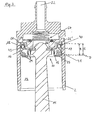
Fig. 1 zeigt eine schematische Darstellung einer Kompressoranordnung inklusive Stromversorgung, Antrieb und Schlauchverbindungen. -
Fig. 2 stellt den Kraftübertragungs- und den Kompressionsmechanismus im Überblick dar. -
Fig. 3 zeigt eine schematische Schnittdarstellung des sich im Zylinder befindlichen Kolbens. -
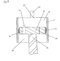
Fig. 4 zeigt eine alternative Ausführungsform eines Kolbens mit Leckagen. -
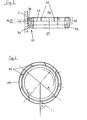
Fig. 5 zeigt einen Querschnitt durch eine Dichtung. -
Fig. 6 zeigt eine Draufsicht auf eine ringförmige Dichtung mit Schnitten. - Gemäß
Fig. 1 wird ein in diesem Fall elektromechanischer Antrieb 1 über eine nicht dargestellte Batterie gespeist, die über einen Zigarettenanzünderstecker 9 und ein Kabel 10 mit einer Steuerungskonsole 12 und über ein weiteres Kabel 13 mit dem Antrieb bzw. Elektromotor 1 verbunden ist. Mit einem an der Konsole 12 befindlichen Wippschalter 11 lässt sich die Stromzufuhr ein- und ausschalten. - Der in einem Antriebsraum 3 bzw. im Zylinder 2 befindliche Kompressionsmechanismus wird über diesen Antrieb 1 betätigt und das Arbeitsmittel, in diesem Fall Luft, wird über einen mit einer Klemme 4 am Auslass 22 des Zylinders 2 befestigten Druckschlauch 5 über ein Manometer 6 zur Druckkontrolle und über einen Auslass 8 zum Destinationsobjekt, z.B. Autoreifen, gedrückt.
- Wie
Fig. 2 überblicksmäßig darstellt, ist eine Antriebswelle des Antriebes 1 im Antriebsraum 3 über eine Kurbel 23 mit einer Schubstange 14 verbunden, die im Zylinder 2 einen Kolben 20 in eine hin- und hergehende Bewegung versetzt, der das von der Wand des Zylinders 2 und dem Kolben 20 begrenzte Volumen des Arbeitsraumes 26 vor dem Kolben 20 bzw. das Volumen des drucklosen Raumes 24 hinter dem Kolben 20 verändert. Durch ein Rückschlagventil 27 wird die aus dem Auslass 22 gedrückte Luft am Zurückströmen in den Arbeitsraum 26 gehindert. - Der in
Fig. 3 vergrößert dargestellte, im Zylinder 2 befindliche Kolben 20 umfasst eine an der Schubstange 14 fixierte tellerförmige Führungsscheibe 16 auf seiner Kopf- bzw. Arbeitsraumseite 26, eine ebenfalls an der Schubstange 14 fixierte und gegebenenfalls mit der Führungsscheibe 16 im Innenbereich fest verbundene tellerförmige Stützscheibe 15 auf seiner Rückseite bzw. seiner dem drucklosen Raum 24 zugekehrten Seite und eine an die Wand des Zylinders 2 anliegende ringförmige Dichtung 17. Die Führungsscheibe 16 ist in den Innenbereich, einen vorzugsweise parallel zur Wand des Zylinders 2 verlaufenden Mittelteil 28 und einen endständigen peripheren Flansch 25' gegliedert. Die Stützscheibe 15 gliedert sich ebenfalls in einen Innenbereich, einen Mittelteil und einen endständigen peripheren Flansch 25. Die Dichtung 17 befindet sich höhenmäßig zwischen den beiden peripheren Flanschen 25, 25' der Stützscheibe 15 und der Führungsscheibe 16 im Umfangsbereich des Kolbens 20. Zwischen der Dichtung 17, der Stützscheibe 15 und der Führungsscheibe 16 bzw. deren peripheren Flanschen 25, 25' befindet sich ein Freiraum 27. - Die der Innenwand des Zylinders 2 zugekehrte Fläche der Dichtung 17 ist konkav nach außen, insbesondere mit kreisförmiger Krümmung, gewölbt, um die leicht pendelnde Bewegung des im vorliegenden Fall nur über die Schubstange 14 und nicht über einen Kreuzkopf geführten Kolbens 20 auszugleichen bzw. zuzulassen und dabei einen ständigen dichten Kontakt zwischen der Wand des Zylinders 2 und der Dichtung 17 zu gewährleisten.
- Die Dichtung 17 weist an ihrer dem Arbeitsraum 26 zugewandten Seite einen im Querschnitt schmalen Kopfbereich 40 und an der dem Arbeitsraum 26 abgewandten Seite einen im Querschnitt breiteren Fußbereich 41 auf. In der Höhe des Kopfbereiches 40 ist an der Innenfläche der Dichtung 17 vorteilhafterweise eine Ausnehmung 43 ausgebildet, in die ein Federring 18 insbesondere fest und vorzugsweise mit Passsitz eingesetzt ist. Dieser Federring 18 liegt demgemäß zwischen dem Mittelteil 28 der Führungsscheibe 16 und dem Kopfbereich 40 der Dichtung 17. Der Federring 18 ist bei einer Hubbewegung des Kolbens 20 entlang bzw. vor diesem Mittelteil 28 der Führungsscheibe 16 auf- und ab bewegbar, wobei seine Aufwärtsbewegung bzw, sein Aufwärtsweg vom peripheren Flansch 25' der Führungsscheibe 16 begrenzt ist. Die Dichtung 17 wird mittels dieses Federringes 18 radial nach außen bzw. an die seitliche Wand des Zylinders 2 gedrückt und verhindert dort einen unerwünschten Gasdurchtritt. Anstelle des Federringes 18 kann auch ein federnder Spannring eingesetzt werden. In beiden Fällen ist jedoch ein Luftdurchtritt zwischen dem Freiraum 27 und dem Arbeitsraum 26 an dieser Stelle möglich.
- Die Höhe H der Dichtung 17, gemessen in Bewegungsrichtung des Kolbens 20, ist geringer als der zwischen den Innenseiten der peripheren Flanschen 25, 25' der Stützscheibe 15 und der Führungsscheibe 16 gemessene Abstand A. Dementsprechend ist die Bewegungsamplitude der Dichtung 17 auf die Differenz D zwischen der Höhe H der Dichtung 17 und dem Abstand A der peripheren Flansche 25, 25' der Stützscheibe 15 und der Führungsscheibe 16 beschränkt. Diese Ausführung bewirkt bei einer Ansaugbewegung, das heißt bei einer Bewegung des Kolbens 20 in Richtung der Kurbel 23, ein Abheben der Dichtung 17 von der Stützscheibe 15 um den Betrag D und ermöglicht damit ein Nachströmen von Gas über den Freiraum 27 in den kopfseitigen Arbeitsraum 26. Beim Kompressionshub wird die Dichtung 17 dicht an den peripheren Flansch 25 der Stützscheibe 15 gedrückt und ein Gasdurchtritt ist nur mehr durch die im folgenden beschriebenen definierten Leckagen 19 möglich. Die im Arbeitsraum 26 komprimierte Luft wird durch ein Rückschlagventil 27 aus dem Auslass 22 gedrückt und durch dieses Rückschlagventil 27 gleichzeitig am Zurückströmen in den Arbeitsraum 26 gehindert.
- Die Dichtung 17 besteht aus einem weitgehend hitzestabilen und/oder weitgehend abriebfesten Polymer, insbesondere mit guten Lauf- und Gleiteigenschaften, vorzugsweise Polytetrafluorethylen (PTFE, Teflon) oder Polytetrafluorethylen-Compounds, und kann gegebenenfalls mit Kohle- oder Kohlenstofffasern und/oder -partikeln in einem Anteil von 10 bis zu 20 Gew-%, vorzugsweise von 15 bis 25 Gew-%, des PTFE- bzw. PTFE-Compound-Gewichts, verstärkt werden.
- Die Anzahl der Leckagen 19, ebenso wie ihre Form bzw. Querschnittsform richtet sich nach der Leistung der Antriebsmechanismus, der Höhe des Anfangsgegendrucks, der Größe und Bauart der Kompressoreinrichtung, der Form des Kolbens usw. Die Leckagen 19 können durch Bohrungen, Einfräsungen, Ausnehmungen, Einsickungen oder dgl. ausgebildet werden, wobei deren Formgebung auch durch die Herstellungsmethode bestimmt wird. Dementsprechend können die Leckagen 19 im Querschnitt rund, eckig oder auch unregelmäßig geformt ausbildet sein. Die gesamte Querschnittsfläche der zumindest einen Leckage 19 beträgt pro cm3 Hubvolumen des Kolbens 20 zwischen 0,005 und 0,1 mm2, vorzugsweise 0,01 und 0,06 mm2.
- Die Ausbildung der Leckagen 19 kann konstruktionsbedingt in der Stützscheibe 15 und/oder der Führungsscheibe 16 erfolgen, sowohl in den Außenbereichen, also den peripheren Flanschen 25, 25', insbesondere im peripheren Flansch 25 der Stützscheibe 15, als auch in den Innenbereichen, wobei zu beachten ist, dass bei Ausbildung in den fest und plan miteinander verbundenen Innenbereichen der Scheiben 15,16, die Leckagen 19 vorteilhafterweise fluchtend angeordnet sind. Des Weiteren besteht die Möglichkeit der Ausbildung von Leckagen im gesamten Bereich der Dichtung 17, insbesondere in der der Innenseite des peripheren Flansches 25 der Stützscheibe 15 zugekehrten Endfläche der Dichtung 17.
- Eine alternative Ausführungsform eines Kompressionsmechanismus mit Anlaufentlastung ist in
Fig. 4 dargestellt. Hierbei wird ein von einer Schubstange bzw. Kolbenstange 14 angetriebener Kolben 32 in dem Zylinder 2 hin- und her bewegt. Dieser Kolben 32 teilt den Zylinder 2 wie auch inFig. 2 undFig. 3 in einen kopfseitigen Arbeitsraum 26 und einen drucklosen Raum 24. Eine ringförmige Dichtung 33, die dicht an der Wand des Zylinders 2 anliegt, soll einen an dieser Stelle unerwünschten Gasdurchtritt verhindern. Im Kolben 32 ist zumindest eine definierte Leckage 19 mit einer im Vergleich zur Querschnittsfläche des Kolbens 32 bzw. des Zylinders 2 geringen Querschnittsfläche sowie eine mit einem Rückschlagventil 37 verschließbare Ansaugöffnung 38 mit einer größeren Querschnittsfläche ausgebildet. Bei einer Kompressionsbewegung des Kolbens 32 verschließt das Rückschlagventil 37 die Durchlassöffnung 38. Nur die Leckage 19 erlaubt einen geringen definierten Gasdurchtritt, der den im Arbeitsraum 26 bestehenden bzw. auf den Kolben 32 einwirkenden Druck mindert und damit die Anlaufentlastung verwirklicht. Die Luft wird über einen in der Wand des Zylinders 2 befindlichen Auslass 22 über ein weiteres Rückschlagventil 37' zum Destinationsobjekt gedrückt. Bei einer Ansaugbewegung öffnet sich das Rückschlagventil 38 und erlaubt freien Gasdurchtritt durch die Durchlassöffnung 38 und damit einen raschen Nachstrom von "frischer Luft" aus dem drucklosen Raum 34 unter dem Kolben in den Arbeitsraum 26. Gleichzeitig schließt das Rückschlagventil 37' und verhindert ein Zurückströmen der Luft aus dem Destinationsobjekt in den Arbeitsraum 26. - Für die Form und Ausbildung der Leckage(n) 19 gilt im Wesentlichen das oben erwähnte. Die Leckage kann auch im Ventil 37 ausgebildet sein.
-
Fig. 5 zeigt einen Querschnitt durch die Dichtung 17. Gut zu erkennen sind der dem Arbeitsraum 26 zugekehrte, im Querschnitt schmale Kopfbereich 40 mit der an seiner Innenseite für den Federring 18 vorgesehenen Ausnehmung 43 und der etwas dickere Fußbereich 41. Im Kopfbereich 40 sind Schnitte 45 ausgebildet. Zu Charakteristik der Schnitte 45 ist zu bemerken, dass die Schnitte 45 ohne Materialabtragung ausgebildet werden, also nicht gefräst, gesägt o.ä. werden. Die Schnitte 45 reichen, ausgehend von der oberen Endfläche des Kopfbereichs 40 der Dichtung 17, mindestens bis zum Beginn des Berührungsbereichs 44 der Dichtung 17 mit der Innenwand des Zylinders 2, der sich in der Praxis durch die Kompression der Dichtung 17 an die Wand des Zylinders 2 bzw. durch die taumelnden Bewegungen des Kolbens 20 ergibt. Vorzugsweise reichen die Schnitte 45 jedoch, ausgehend von der oberen Endfläche des Kopfbereichs 40 der Dichtung 17, bis zur inFig. 5 geometrischen ermittelten, theoretischen Berührungslinie 42 der konkaven Dichtung 17 mit der Innenwand des Zylinders 2. Eine Alternative ist auch, dass die Schnitte 45, ausgehend von der oberen Endfläche des Kopfbereichs 40 der Dichtung 17, mindestens bis zum unteren Ende der Ausnehmung 43 reichen. Maximal reichen die Schnitte 45, gemessen von der oberen Endfläche des Kopfbereichs 40 der Dichtung 17, bis zum Beginn des Fußbereichs 41 der Dichtung 17, also bis in eine maximale Tiefe T. -
Fig. 6 zeigt eine Draufsicht vom Arbeitsraum 26 auf die ringförmige Dichtung 17. Die Schnitte 45 durchsetzen den Kopfbereich 40 der Dichtung 17 vollständig. Die vorzugsweise 6 bis 12, insbesondere 8 bis 10, hier 9 Schnitte 45 sind längs des Umfangs der ringförmigen Dichtung 17 und in gleichen Abständen zueinander verteilt und sind relativ zum Radius R der Dichtung 17 in die gleiche Richtung geneigt, vorzugsweise mit einem Winkel a zwischen 30 und 80°, insbesondere zwischen 40 und 70°. Die Flächen der Schnitte 45 sind eben und sind senkrecht zu der von der Dichtung 17 aufgespannten Ebene ausgerichtet. Die Schnitte 45 sind vorteilhafterweise untereinander gleich ausgebildet bzw. besitzen gleiche Form bzw. Abmessungen. - Unter Leckage wird eine ständig offene (Gas)Durchlassverbindung zwischen dem vor und dem hinter dem Kolben liegenden Raum verstanden.
Claims (7)
- Einrichtung zur Verdichtung von Gasen, insbesondere Luft, vorzugsweise zur Befüllung von Reifen von Kraftfahrzeugen, mit einem von einem insbesondere elektromechanischen, vorzugsweise an eine Batterie angeschlossenen, Antrieb angetriebenen, in einem Zylinder gelagerten, auf- und ab bewegbaren Kolben, dadurch gekennzeichnet, dass in dem Kolben (20) zumindest eine definierte Leckage (19) mittels einer ständig offenen Durchlassverbindung zum Gasdurchtritt während des Kompressionshubes von dem vor dem Kolben (20) liegenden Arbeitsraum (26) zu dem hinter dem Kolben (20) liegenden drucklosen Raum (24) ausgebildet ist.
- Einrichtung nach Anspruch 1, dadurch gekennzeichnet, dass der Kolben (20) eine an seiner Schubstange (14) fixierte, vorzugsweise tellerförmige, Führungsscheibe (16) mit einem, vorzugsweise parallel zur Wand des Zylinders (2) verlaufenden, Mittelteil (28) und einem peripheren Flansch (25') auf seiner Kopfseite bzw. der dem Arbeitsraum (26) zugekehrten Seite, eine an der Schubstange (14) fixierte, vorzugsweise tellerförmige, Stützscheibe (15) mit einem Mittelteil und einem peripheren Flansch (25) auf seiner Rückseite bzw. der dem drucklosen Raum (24) zugekehrten Seite und eine höhenmäßig zwischen den beiden peripheren Flanschen (25, 25') der Stützscheibe (15) und der Führungsscheibe (16) im Umfangsbereich des Kolbens (20) befindliche, an die Innenwand des Zylinders (2) anliegende ringförmige Dichtung (17) umfasst, wobei gegebenenfalls die Dichtung (17) aus einem weitgehend hitzestabilen und/oder weitgehend abriebfesten Polymer, insbesondere mit guten Lauf- und Gleiteigenschaften, vorzugsweise Polytetrafluorethylen (PTFE, Teflon) oder Polytetrafluorethylen-Compounds, gegebenenfalls verstärkt mit Kohle- oder Kohlenstofffasern und/oder - partikeln in einem Anteil von 10 bis zu 20 Gew-%, vorzugsweise von 15 bis 25 Gew-%, des PTFE- bzw. PTFE-Compound-Gewichts, gebildet ist.
- Einrichtung nach Anspruch 1 oder 2, dadurch gekennzeichnet, dass die der Wand des Zylinders (2) zugekehrte Außenfläche der Dichtung (17) konkav nach außen, insbesondere mit kreisförmiger Krümmung, gewölbt ist und/oder- dass die Dichtung (17) an ihrer dem Arbeitsraum (26) zugewandten Seite einen im Querschnitt schmalen Kopfbereich (40) und an der dem Arbeitsraum (26) abgewandten Seite einen im Querschnitt gegenüber dem Kopfbereich (40) breiteren Fußbereich (41) aufweist, wobei gegebenenfalls an der Innenfläche des Kopfbereiches (40) eine Ausnehmung (43) ausgebildet ist.
- Einrichtung nach Anspruch 1, 2 oder 3, dadurch gekennzeichnet,- dass an der Innenfläche der Dichtung (17) ein zwischen der Dichtung (17) und dem Mittelteil (28) der Führungsscheibe (16) liegender, vorzugsweise in die Ausnehmung (43) im Kopfbereich (40) der Dichtung (17), insbesondere mit Passsitz eingesetzter, kreisringförmiger, luftdurchlässiger, die Dichtung (17) an die Innenwand des Zylinders (2) drückender Federring (18), vorzugsweise ein Schraubenfederdruckring, anliegt und/oder- dass die Höhe (H) der Dichtung (17) geringer ist als der zwischen den Innenseiten der peripheren Flansche (25, 25') der Stützscheibe (15) und der Führungsscheibe (16) gemessene Abstand (A) und/oder- dass der Federring (18) im Zuge der Hubbewegungen des Kolbens (20) dem Mittelteil (28) der Führungsscheibe (16) entlang auf- und ab bewegbar ist und dass die Aufwärtsbewegung bzw. der Aufwärtsweg des Federrings (18) vom peripheren Flansch (25') der Führungsscheibe (16) begrenzt ist.
- Einrichtung nach einem der Ansprüche 2 bis 4, dadurch gekennzeichnet,- dass die Dichtung (17) beim Kompressionshub des Kolbens (20) mit einer dem Arbeitsraum (26) abgewandten Endfläche auf dem peripheren Flansch (25) der Stützscheibe (15) aufliegt und dass beim Ansaughub des Kolbens (20) der Federring (18) und/oder die Dichtung (17) mit einer dem Arbeitsraum (26) zugewandten Endfläche auf dem peripheren Flansch (25') der Führungsscheibe (16) aufliegen und/oder- dass die Stützscheibe (15) und die Führungsscheibe (16) mit der Schubstange (14) und in ihren Innenbereichen gegebenenfalls miteinander verbunden sind.
- Einrichtung nach einem der Ansprüche 1 bis 5, dadurch gekennzeichnet,- dass die gesamte Querschnittsfläche der zumindest einen Leckage (19) pro cm3 Hubvolumen des Kolbens (20) zwischen 0,005 und 0,1 mm2, vorzugsweise 0,01 und 0,06 mm2, beträgt und/oder- dass die Leckage(n) (19) in Form von Einfräsungen, Ausnehmungen, Einsickungen, Bohrungen oder dgl. in der Stützscheibe (15) und/oder der Führungsscheibe (16) bzw. im peripheren Flansch (25) der Stützscheibe (15) und/oder in der Dichtung (17), insbesondere in der dem peripheren Flansch (25) der Stützscheibe (15) zugewandten Endfläche der Dichtung (17) ausgebildet ist (sind) und/oder- dass die Leckagen (19) in der Stützscheibe (15) und in der Führungsscheibe (16) fluchten.
- Einrichtung nach einem der Ansprüche 2 bis 6, dadurch gekennzeichnet,- dass in der Dichtung (17) eine Anzahl von Schnitten (45), vorzugsweise 6 bis 12, insbesondere 8 bis 10, ausgebildet ist, wobei gegebenenfalls die Schnitte (45), ausgehend von der oberen Endfläche des Kopfbereichs (40) der Dichtung (17), mindestens bis in eine Tiefe bis zum Beginn des Berührungsbereichs (44) der Dichtung (17) mit der Innenwand des Zylinders (2), vorzugsweise bis zur theoretischen geometrischen Berührungslinie (42) der Dichtung (17) mit der Innenwand des Zylinders (2), ausgebildet sind und/oder- dass die Schnitte (45), ausgehend von der oberen Endfläche des Kopfbereichs (40) der Dichtung (17), mindestens bis zum unteren Ende der Ausnehmung (43) ausgebildet sind und/oder- dass die Schnitte (45) bis maximal zum Beginn des Fußbereichs (41) der Dichtung (17), d.h. bis in eine Tiefe (T), gemessen von der oberen Endfläche des Kopfbereichs (40) der Dichtung (17), ausgebildet sind und/oder- dass die Flächen der Schnitte (45) eben ausgebildet sind und senkrecht zu der von der Dichtung (17) aufgespannten Ebene verlaufen und/oder- dass die Schnitte (45) längs des Umfangs der ringförmigen Dichtung (17) regelmäßig und in gleichen Abständen zueinander verteilt sind und/oder- dass alle Schnitte (45) relativ zum Radius (R) der Dichtung (17) in die gleiche Richtung geneigt sind, vorzugsweise mit einem Winkel (a) zwischen 30 und 80°, insbesondere zwischen 40 und 70° und/oder- dass die Schnitte (45) den Kopfbereich (40) der Dichtung (17) vom Außenumfang bis in den Innenbereich der Dichtung (17) vollständig durchsetzen und/oder- dass die Schnitte (45) untereinander gleiche Form und/oder gleiche Abmessungen besitzen.
Applications Claiming Priority (3)
| Application Number | Priority Date | Filing Date | Title |
|---|---|---|---|
| AT0112602A AT414269B (de) | 2002-07-24 | 2002-07-24 | Einrichtung zur verdichtung von gasen |
| AT11262002 | 2002-07-24 | ||
| PCT/AT2003/000209 WO2004011804A1 (de) | 2002-07-24 | 2003-07-23 | Einrichtung zur verdichtung von gasen |
Publications (2)
| Publication Number | Publication Date |
|---|---|
| EP1527279A1 EP1527279A1 (de) | 2005-05-04 |
| EP1527279B1 true EP1527279B1 (de) | 2008-04-02 |
Family
ID=30773866
Family Applications (1)
| Application Number | Title | Priority Date | Filing Date |
|---|---|---|---|
| EP03739847A Expired - Lifetime EP1527279B1 (de) | 2002-07-24 | 2003-07-23 | Einrichtung zur verdichtung von gasen |
Country Status (5)
| Country | Link |
|---|---|
| EP (1) | EP1527279B1 (de) |
| AT (2) | AT414269B (de) |
| AU (1) | AU2003281720A1 (de) |
| DE (1) | DE50309544D1 (de) |
| WO (1) | WO2004011804A1 (de) |
Cited By (1)
| Publication number | Priority date | Publication date | Assignee | Title |
|---|---|---|---|---|
| EP4039977A4 (de) * | 2019-10-01 | 2023-10-04 | Hitachi Industrial Equipment Systems Co., Ltd. | Verdichter |
Families Citing this family (5)
| Publication number | Priority date | Publication date | Assignee | Title |
|---|---|---|---|---|
| DE102006011560A1 (de) * | 2006-03-10 | 2007-09-13 | Linde Ag | Verdichter mit Schwenkkolben |
| JP5381891B2 (ja) * | 2010-05-11 | 2014-01-08 | マックス株式会社 | ロッキングピストンのシール構造 |
| EP3150852B1 (de) * | 2015-10-01 | 2020-12-09 | Moog GmbH | Zylinderanordnung und pumpenanordnung |
| US20210164463A1 (en) | 2017-10-19 | 2021-06-03 | Active Tools International (Hk) Ltd. | Air compressor cylinder, air compressor, vehicle seat, and vehicle |
| WO2023067418A1 (en) * | 2021-10-19 | 2023-04-27 | Mixtron S.R.L. | Proportional volumetric dosing unit |
Family Cites Families (14)
| Publication number | Priority date | Publication date | Assignee | Title |
|---|---|---|---|---|
| US1494243A (en) * | 1923-03-16 | 1924-05-13 | John B Colt | Piston head for pumps |
| US2186623A (en) * | 1938-02-25 | 1940-01-09 | Henry E Brandt | Safety pump plunger |
| US2274403A (en) * | 1940-06-24 | 1942-02-24 | Arthur J Filkins | Chimney |
| DE843135C (de) * | 1950-01-25 | 1952-07-07 | Mannesmann Fa A | Anlassvorrichtung fuer Kolbenverdichter |
| GB892441A (en) * | 1959-08-27 | 1962-03-28 | Mads Clausen | Improvements in or relating to motor driven piston compressors |
| US3897072A (en) * | 1973-02-12 | 1975-07-29 | Crane Packing Co | Slit ring with connecting membrane |
| JPS62255666A (ja) * | 1986-04-28 | 1987-11-07 | N D C Kk | ストラツト用ピストン部材 |
| DE3710403A1 (de) * | 1987-03-28 | 1988-10-06 | Lechler Elring Dichtungswerke | Komplettkolben |
| DE4203384C2 (de) * | 1992-02-06 | 1994-10-20 | Hunger Walter Dr Ing E H | Kolben einer Kolbenmaschine |
| DE4429097A1 (de) * | 1994-08-17 | 1996-02-22 | Thurner Bayer Druckguss | Kolbenverdichter für gasförmige Medien |
| DE19514918C2 (de) * | 1995-04-22 | 1999-01-07 | Mtu Friedrichshafen Gmbh | Kolben für Brennkraftmaschine |
| DK28697A (da) * | 1997-03-14 | 1998-09-15 | Man B & W Diesel As | Stempel til en forbrænmdingsmotor, navnlig en totakts krydshovedmotor af dieseltypen |
| DE29717654U1 (de) * | 1997-10-02 | 1998-11-12 | Alusuisse Bayrisches Druckguß-Werk GmbH & Co. KG, 85570 Markt Schwaben | Kolben für einen Kolbenverdichter |
| DE29814962U1 (de) * | 1998-08-20 | 1999-11-04 | Alusuisse Bayrisches Druckguß-Werk GmbH & Co. KG, 85570 Markt Schwaben | Kolben für einen Kolbenverdichter |
-
2002
- 2002-07-24 AT AT0112602A patent/AT414269B/de not_active IP Right Cessation
-
2003
- 2003-07-23 DE DE50309544T patent/DE50309544D1/de not_active Expired - Lifetime
- 2003-07-23 AU AU2003281720A patent/AU2003281720A1/en not_active Abandoned
- 2003-07-23 EP EP03739847A patent/EP1527279B1/de not_active Expired - Lifetime
- 2003-07-23 AT AT03739847T patent/ATE391236T1/de not_active IP Right Cessation
- 2003-07-23 WO PCT/AT2003/000209 patent/WO2004011804A1/de not_active Ceased
Cited By (2)
| Publication number | Priority date | Publication date | Assignee | Title |
|---|---|---|---|---|
| EP4039977A4 (de) * | 2019-10-01 | 2023-10-04 | Hitachi Industrial Equipment Systems Co., Ltd. | Verdichter |
| US12116996B2 (en) | 2019-10-01 | 2024-10-15 | Hitachi Industrial Equipment Systems Co., Ltd. | Compressor with piston ring arrangement on piston |
Also Published As
| Publication number | Publication date |
|---|---|
| WO2004011804A1 (de) | 2004-02-05 |
| EP1527279A1 (de) | 2005-05-04 |
| ATA11262002A (de) | 2006-01-15 |
| ATE391236T1 (de) | 2008-04-15 |
| DE50309544D1 (de) | 2008-05-15 |
| AU2003281720A1 (en) | 2004-02-16 |
| AT414269B (de) | 2006-10-15 |
Similar Documents
| Publication | Publication Date | Title |
|---|---|---|
| EP0733802B1 (de) | Membranpumpe mit einer Formmembran | |
| DE4229978C2 (de) | Kompressor mit mehreren Axialkolben und Druckausgleichseinrichtungen | |
| DE2559238A1 (de) | Gasbetaetigte vorrichtung fuer den antrieb der nachladeeinrichtung eines automatischen gewehrs mit gasabzapfung | |
| DE2511516B2 (de) | Ringanordnung zur Abdichtung und Lagerffihrung eines Bremszylinderkolbens | |
| DE1525819A1 (de) | Dichtung fuer eine Kolbenstange | |
| DE2502566B2 (de) | Membranpumpe | |
| DE2211178A1 (de) | Dichtungssatz und diesen enthaltende Dichtungsgruppe für Hochdruckpumpen od. dgl | |
| DE3611952A1 (de) | Kolbenpumpe mit verbesserter abdichtung | |
| DE102009047217A1 (de) | Kolbenplumpe | |
| EP1527279B1 (de) | Einrichtung zur verdichtung von gasen | |
| DE3934124A1 (de) | Druckluftgetriebene pumpenanordnung | |
| DE10261585B4 (de) | Saugventil eines Kolbenverdichters | |
| WO2007137941A1 (de) | Radialkolbenpumpe zur kraftstoff-hochdruckversorgung bei einer brennkraftmaschine | |
| EP1527278B1 (de) | Einrichtung zur verdichtung von gasen | |
| EP0312597A1 (de) | Volumenverdrängungsmaschinenkolben | |
| DE2029711A1 (de) | Strömungsmittelbetriebener Motor | |
| DE60312540T3 (de) | Absperrschieber | |
| DE1948491A1 (de) | Verdichterventil mit einer Einrichtung zur Liefermengenregelung | |
| DE2239488A1 (de) | Kolbenmaschine, insbesondere trockenlauf-kolbenverdichter, mit fuehrungsring | |
| DE3043054A1 (de) | Fluegelzellenpume | |
| DE2330637A1 (de) | Druckgasschusswaffe | |
| DE102017113250A1 (de) | Kolben für eine Pleuelstange und Pleuelstange | |
| EP1662141B1 (de) | Axialkolbenverdichter | |
| DE202011108107U1 (de) | Stufenkolbenpumpe zum Fördern vier unterschiedlicher Flüssigkeiten mit einer Dichtung und Schmierung des Stufenkolbens ausschließlich mittels einer schmierfähigen Flüssigkeit über Nuten am Kolbenumfang | |
| DE3931487A1 (de) | Abdichtung fuer kolben in axialkolbenmaschinen |
Legal Events
| Date | Code | Title | Description |
|---|---|---|---|
| PUAI | Public reference made under article 153(3) epc to a published international application that has entered the european phase |
Free format text: ORIGINAL CODE: 0009012 |
|
| 17P | Request for examination filed |
Effective date: 20050203 |
|
| AK | Designated contracting states |
Kind code of ref document: A1 Designated state(s): AT BE BG CH CY CZ DE DK EE ES FI FR GB GR HU IE IT LI LU MC NL PT RO SE SI SK TR |
|
| AX | Request for extension of the european patent |
Extension state: AL LT LV MK |
|
| DAX | Request for extension of the european patent (deleted) | ||
| GRAP | Despatch of communication of intention to grant a patent |
Free format text: ORIGINAL CODE: EPIDOSNIGR1 |
|
| GRAS | Grant fee paid |
Free format text: ORIGINAL CODE: EPIDOSNIGR3 |
|
| GRAA | (expected) grant |
Free format text: ORIGINAL CODE: 0009210 |
|
| AK | Designated contracting states |
Kind code of ref document: B1 Designated state(s): AT BE BG CH CY CZ DE DK EE ES FI FR GB GR HU IE IT LI LU MC NL PT RO SE SI SK TR |
|
| REG | Reference to a national code |
Ref country code: GB Ref legal event code: FG4D Free format text: NOT ENGLISH |
|
| REG | Reference to a national code |
Ref country code: IE Ref legal event code: FG4D Free format text: LANGUAGE OF EP DOCUMENT: GERMAN Ref country code: CH Ref legal event code: EP |
|
| REF | Corresponds to: |
Ref document number: 50309544 Country of ref document: DE Date of ref document: 20080515 Kind code of ref document: P |
|
| PG25 | Lapsed in a contracting state [announced via postgrant information from national office to epo] |
Ref country code: SI Free format text: LAPSE BECAUSE OF FAILURE TO SUBMIT A TRANSLATION OF THE DESCRIPTION OR TO PAY THE FEE WITHIN THE PRESCRIBED TIME-LIMIT Effective date: 20080402 |
|
| NLV1 | Nl: lapsed or annulled due to failure to fulfill the requirements of art. 29p and 29m of the patents act | ||
| REG | Reference to a national code |
Ref country code: IE Ref legal event code: FD4D |
|
| PG25 | Lapsed in a contracting state [announced via postgrant information from national office to epo] |
Ref country code: PT Free format text: LAPSE BECAUSE OF FAILURE TO SUBMIT A TRANSLATION OF THE DESCRIPTION OR TO PAY THE FEE WITHIN THE PRESCRIBED TIME-LIMIT Effective date: 20080903 Ref country code: BG Free format text: LAPSE BECAUSE OF FAILURE TO SUBMIT A TRANSLATION OF THE DESCRIPTION OR TO PAY THE FEE WITHIN THE PRESCRIBED TIME-LIMIT Effective date: 20080702 Ref country code: FI Free format text: LAPSE BECAUSE OF FAILURE TO SUBMIT A TRANSLATION OF THE DESCRIPTION OR TO PAY THE FEE WITHIN THE PRESCRIBED TIME-LIMIT Effective date: 20080402 Ref country code: ES Free format text: LAPSE BECAUSE OF FAILURE TO SUBMIT A TRANSLATION OF THE DESCRIPTION OR TO PAY THE FEE WITHIN THE PRESCRIBED TIME-LIMIT Effective date: 20080713 Ref country code: NL Free format text: LAPSE BECAUSE OF FAILURE TO SUBMIT A TRANSLATION OF THE DESCRIPTION OR TO PAY THE FEE WITHIN THE PRESCRIBED TIME-LIMIT Effective date: 20080402 |
|
| EN | Fr: translation not filed | ||
| PG25 | Lapsed in a contracting state [announced via postgrant information from national office to epo] |
Ref country code: SE Free format text: LAPSE BECAUSE OF FAILURE TO SUBMIT A TRANSLATION OF THE DESCRIPTION OR TO PAY THE FEE WITHIN THE PRESCRIBED TIME-LIMIT Effective date: 20080702 Ref country code: CZ Free format text: LAPSE BECAUSE OF FAILURE TO SUBMIT A TRANSLATION OF THE DESCRIPTION OR TO PAY THE FEE WITHIN THE PRESCRIBED TIME-LIMIT Effective date: 20080402 Ref country code: DK Free format text: LAPSE BECAUSE OF FAILURE TO SUBMIT A TRANSLATION OF THE DESCRIPTION OR TO PAY THE FEE WITHIN THE PRESCRIBED TIME-LIMIT Effective date: 20080402 Ref country code: IE Free format text: LAPSE BECAUSE OF FAILURE TO SUBMIT A TRANSLATION OF THE DESCRIPTION OR TO PAY THE FEE WITHIN THE PRESCRIBED TIME-LIMIT Effective date: 20080402 |
|
| PLBE | No opposition filed within time limit |
Free format text: ORIGINAL CODE: 0009261 |
|
| STAA | Information on the status of an ep patent application or granted ep patent |
Free format text: STATUS: NO OPPOSITION FILED WITHIN TIME LIMIT |
|
| PG25 | Lapsed in a contracting state [announced via postgrant information from national office to epo] |
Ref country code: SK Free format text: LAPSE BECAUSE OF FAILURE TO SUBMIT A TRANSLATION OF THE DESCRIPTION OR TO PAY THE FEE WITHIN THE PRESCRIBED TIME-LIMIT Effective date: 20080402 Ref country code: RO Free format text: LAPSE BECAUSE OF FAILURE TO SUBMIT A TRANSLATION OF THE DESCRIPTION OR TO PAY THE FEE WITHIN THE PRESCRIBED TIME-LIMIT Effective date: 20080402 |
|
| REG | Reference to a national code |
Ref country code: CH Ref legal event code: PL |
|
| 26N | No opposition filed |
Effective date: 20090106 |
|
| GBPC | Gb: european patent ceased through non-payment of renewal fee |
Effective date: 20080723 |
|
| PG25 | Lapsed in a contracting state [announced via postgrant information from national office to epo] |
Ref country code: MC Free format text: LAPSE BECAUSE OF NON-PAYMENT OF DUE FEES Effective date: 20080731 |
|
| PG25 | Lapsed in a contracting state [announced via postgrant information from national office to epo] |
Ref country code: EE Free format text: LAPSE BECAUSE OF FAILURE TO SUBMIT A TRANSLATION OF THE DESCRIPTION OR TO PAY THE FEE WITHIN THE PRESCRIBED TIME-LIMIT Effective date: 20080402 |
|
| PG25 | Lapsed in a contracting state [announced via postgrant information from national office to epo] |
Ref country code: CH Free format text: LAPSE BECAUSE OF NON-PAYMENT OF DUE FEES Effective date: 20080731 Ref country code: GB Free format text: LAPSE BECAUSE OF NON-PAYMENT OF DUE FEES Effective date: 20080723 Ref country code: LI Free format text: LAPSE BECAUSE OF NON-PAYMENT OF DUE FEES Effective date: 20080731 |
|
| PG25 | Lapsed in a contracting state [announced via postgrant information from national office to epo] |
Ref country code: IT Free format text: LAPSE BECAUSE OF FAILURE TO SUBMIT A TRANSLATION OF THE DESCRIPTION OR TO PAY THE FEE WITHIN THE PRESCRIBED TIME-LIMIT Effective date: 20080402 |
|
| PG25 | Lapsed in a contracting state [announced via postgrant information from national office to epo] |
Ref country code: CY Free format text: LAPSE BECAUSE OF FAILURE TO SUBMIT A TRANSLATION OF THE DESCRIPTION OR TO PAY THE FEE WITHIN THE PRESCRIBED TIME-LIMIT Effective date: 20080402 |
|
| PG25 | Lapsed in a contracting state [announced via postgrant information from national office to epo] |
Ref country code: AT Free format text: LAPSE BECAUSE OF NON-PAYMENT OF DUE FEES Effective date: 20080723 |
|
| PG25 | Lapsed in a contracting state [announced via postgrant information from national office to epo] |
Ref country code: LU Free format text: LAPSE BECAUSE OF NON-PAYMENT OF DUE FEES Effective date: 20080723 Ref country code: HU Free format text: LAPSE BECAUSE OF FAILURE TO SUBMIT A TRANSLATION OF THE DESCRIPTION OR TO PAY THE FEE WITHIN THE PRESCRIBED TIME-LIMIT Effective date: 20081003 Ref country code: BE Free format text: LAPSE BECAUSE OF NON-PAYMENT OF DUE FEES Effective date: 20080731 |
|
| PG25 | Lapsed in a contracting state [announced via postgrant information from national office to epo] |
Ref country code: TR Free format text: LAPSE BECAUSE OF FAILURE TO SUBMIT A TRANSLATION OF THE DESCRIPTION OR TO PAY THE FEE WITHIN THE PRESCRIBED TIME-LIMIT Effective date: 20080402 |
|
| PG25 | Lapsed in a contracting state [announced via postgrant information from national office to epo] |
Ref country code: GR Free format text: LAPSE BECAUSE OF FAILURE TO SUBMIT A TRANSLATION OF THE DESCRIPTION OR TO PAY THE FEE WITHIN THE PRESCRIBED TIME-LIMIT Effective date: 20080703 |
|
| PG25 | Lapsed in a contracting state [announced via postgrant information from national office to epo] |
Ref country code: FR Free format text: LAPSE BECAUSE OF FAILURE TO SUBMIT A TRANSLATION OF THE DESCRIPTION OR TO PAY THE FEE WITHIN THE PRESCRIBED TIME-LIMIT Effective date: 20090123 |
|
| PGFP | Annual fee paid to national office [announced via postgrant information from national office to epo] |
Ref country code: DE Payment date: 20170724 Year of fee payment: 15 |
|
| REG | Reference to a national code |
Ref country code: DE Ref legal event code: R119 Ref document number: 50309544 Country of ref document: DE |
|
| PG25 | Lapsed in a contracting state [announced via postgrant information from national office to epo] |
Ref country code: DE Free format text: LAPSE BECAUSE OF NON-PAYMENT OF DUE FEES Effective date: 20190201 |