EP1526356B1 - Procédé pour mesurer la surface courbée d'un objet - Google Patents
Procédé pour mesurer la surface courbée d'un objet Download PDFInfo
- Publication number
- EP1526356B1 EP1526356B1 EP04024863A EP04024863A EP1526356B1 EP 1526356 B1 EP1526356 B1 EP 1526356B1 EP 04024863 A EP04024863 A EP 04024863A EP 04024863 A EP04024863 A EP 04024863A EP 1526356 B1 EP1526356 B1 EP 1526356B1
- Authority
- EP
- European Patent Office
- Prior art keywords
- workpiece
- measuring
- curved surface
- coordinate system
- theoretical
- Prior art date
- Legal status (The legal status is an assumption and is not a legal conclusion. Google has not performed a legal analysis and makes no representation as to the accuracy of the status listed.)
- Expired - Lifetime
Links
- 238000000034 method Methods 0.000 title claims description 58
- 238000005259 measurement Methods 0.000 claims description 77
- 230000014509 gene expression Effects 0.000 claims description 74
- 239000013598 vector Substances 0.000 claims description 70
- 239000000523 sample Substances 0.000 claims description 45
- 238000013461 design Methods 0.000 claims description 25
- 241001422033 Thestylus Species 0.000 claims description 22
- 230000009466 transformation Effects 0.000 claims description 15
- 238000012937 correction Methods 0.000 claims description 4
- 230000001131 transforming effect Effects 0.000 claims description 4
- 238000013329 compounding Methods 0.000 claims description 3
- 238000005520 cutting process Methods 0.000 description 32
- 230000007246 mechanism Effects 0.000 description 22
- 238000012986 modification Methods 0.000 description 9
- 230000004048 modification Effects 0.000 description 9
- 238000012545 processing Methods 0.000 description 8
- 238000003754 machining Methods 0.000 description 6
- 230000008859 change Effects 0.000 description 4
- 238000010586 diagram Methods 0.000 description 4
- 238000006073 displacement reaction Methods 0.000 description 4
- 238000000691 measurement method Methods 0.000 description 4
- 230000008569 process Effects 0.000 description 4
- 238000012546 transfer Methods 0.000 description 4
- 230000005540 biological transmission Effects 0.000 description 3
- 239000011159 matrix material Substances 0.000 description 3
- 238000011161 development Methods 0.000 description 2
- 230000006872 improvement Effects 0.000 description 2
- 238000003860 storage Methods 0.000 description 2
- 238000012935 Averaging Methods 0.000 description 1
- 230000036760 body temperature Effects 0.000 description 1
- 239000003638 chemical reducing agent Substances 0.000 description 1
- 230000001276 controlling effect Effects 0.000 description 1
- 230000001419 dependent effect Effects 0.000 description 1
- 230000009977 dual effect Effects 0.000 description 1
- 230000007613 environmental effect Effects 0.000 description 1
- 238000004519 manufacturing process Methods 0.000 description 1
- 239000000463 material Substances 0.000 description 1
- 230000001105 regulatory effect Effects 0.000 description 1
- 239000000126 substance Substances 0.000 description 1
- 230000003746 surface roughness Effects 0.000 description 1
Images


Classifications
-
- G—PHYSICS
- G01—MEASURING; TESTING
- G01B—MEASURING LENGTH, THICKNESS OR SIMILAR LINEAR DIMENSIONS; MEASURING ANGLES; MEASURING AREAS; MEASURING IRREGULARITIES OF SURFACES OR CONTOURS
- G01B21/00—Measuring arrangements or details thereof, where the measuring technique is not covered by the other groups of this subclass, unspecified or not relevant
- G01B21/02—Measuring arrangements or details thereof, where the measuring technique is not covered by the other groups of this subclass, unspecified or not relevant for measuring length, width, or thickness
- G01B21/04—Measuring arrangements or details thereof, where the measuring technique is not covered by the other groups of this subclass, unspecified or not relevant for measuring length, width, or thickness by measuring coordinates of points
Definitions
- the present invention relates to a method for measuring a curved surface of a workpiece, particularly to a method for measuring a curved surface of a workpiece so as to avoid the interference between the workpiece and a measuring probe.
- a gear is cited as a representative example of a workpiece having such a curved surface and, particularly in the final speed reducer of an automobile or the like, gears such as spiral bevel gears and hypoid gears having tooth flanks of curved surfaces are frequently used as gears to change the direction of a rotation axis and reduce the speed in the transmission of rotation power.
- a spiral bevel gear is configured so that a ring gear and a pinion engage with each other and their axes intersect with each other on the same plane as shown in Fig. 20.
- a hypoid gear although a ring gear and a pinion engage with each other likewise, their axes do not intersect with each other on the same plane and so-called offset is incorporated.
- the features of a hypoid gear are that it has a high degree-of-freedom of spatial allocation in a power transmission system and moreover allows smoother rotation, quieter operation and also higher tooth strength than a spiral bevel gear.
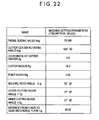
- gear generation is executed with a gear generator based on the theoretical machine setting parameters shown in Fig. 22.
- a gear generator based on the theoretical machine setting parameters shown in Fig. 22.
- a gear pair showing good tooth bearing can not always be obtained due to the mechanical errors and the like of a gear generator.
- a cutter 1 of a gear generator is supported by a cradle 2 so as to be rotatable around the cutter axis zc.
- the base material of a ring gear blank as a workpiece W is supported by a workpiece head 3 so as to be rotatable but the workpiece W does not rotate and is fixed while a tooth of the ring gear is in cutting operation.
- the coordinate system shown in Fig. 23 includes: a machine coordinate system consisting of an origin point Om being the center of a machine, cradle axis (zm axis), H axis (ym axis) and V axis (xm axis: an axis passing through the origin point Om and being perpendicular to the cradle axis (zm axis) and the H axis); and a cutter coordinate system consisting of an origin point Oc being the center of a cutter and xc, yc and zc axes (refer to Fig. 25).
- a gear coordinate system consisting of an origin point Og being the center of a gear and xg, yg and zg axes (refer to Fig. 25).
- the workpiece axis zg and the cradle axis zm are on the same plane and the machine center Om coincides with the gear center Og.
- the offset between the V axis (xm axis) and the xc axis is represented by Hg and the offset between the H axis (ym axis) and the yc axis is represented by Vg.
- Xgc shows the position vector on the locus of a cutting blade edge formed when the cutting blade edge of a cutter 1 rotates around the cutter center Oc.
- Fig. 25 The mutual relationship among the coordinate systems on the ym-zm plane is as shown in Fig. 25.
- the distance from the reference plane Wb of a workpiece to the gear center Og (V axis) is represented by Lg and a machine root angle (an angle formed by the ym axis and the zg axis) is represented by ⁇ gr.
- Mi the i-th measured data
- Mi X ⁇ ui , vi , C ⁇ 1 + ⁇ C ⁇ 1 , C ⁇ 2 + ⁇ C ⁇ 2 , ... , Cn + ⁇ Cn
- the difference between the measured tooth flank data M and a value given by the theoretical tooth flank expression X is determined as residual (M-X).
- an angle ⁇ can be obtained in addition to the estimated machine setting parameters (C1+ ⁇ C1, C2+ ⁇ C2, ..., Cn+ ⁇ Cn) by the aforementioned method and therefore it becomes possible to transform the theoretical tooth flank expression into a measurement coordinate system.
- ⁇ is subordinate to all the gear cutting parameters (C1, C2, ..., Cn)
- the unknowns of C1, C2, ..., Cn and ⁇ , namely n + 1 in total are not solved by simultaneous equations, they are solved by applying dual simultaneous equations related to the least-square method to each combination of ( ⁇ and C1), ( ⁇ and C2), ..., ( ⁇ and Cn), namely n combinations in total.
- WO 02/23292 relates to a method for generating a measuring program for a co-ordinate measuring device.
- a CAD data set of an object to be measured is inputted into a data processing device which controls a co-ordinate measuring device.
- measuring of the object to be measured can be automized and the stylus angle of the measuring touch probe can be automatically adjusted to the orientation of the measuring area.
- An main object of the present invention is to provide: a method for measuring a curved surface of a workpiece that allows to measure with safety and a high degree of accuracy the measurement points of the workpiece having a curved surface such as a tooth flank of a spiral bevel gear; a program thereof; and a medium thereof.
- the axis angle of the stylus of the probe in the event of measuring the curved surface of the workpiece is determined based on the theoretical expression of a workpiece, the measurement can be carried out safely and easily without interference between the probe and the workpiece.
- the computing load can be mitigated.
- the reliability in the computation of the axis angle in the measuring area can be improved. That is, as long as the axis angle is obtained through the above procedure, the interference between the workpiece and the measuring probe can surely be avoided.
- the interference between the workpiece and the measuring probe can further surely be avoided.
- the axis angle is determined based on the shape of the workpiece, the interference between the workpiece and the measuring probe can yet further surely be avoided.
- a measurement part program including a stylus axis angle control command is generated based on the theoretical expression of the workpiece, it is possible to prepare the measurement part program beforehand even before the completion of the machining of the workpiece itself and to start the measurement operation immediately after the completion of the machining of the workpiece, and resultantly the overall production efficiency improves.
- the three-dimensional coordinate values on an objective measuring plane can be obtained even before the completion of the workpiece machining.
- Fig. 1 shows a first embodiment of a method for measuring a curved surface of a workpiece by using a coordinate measuring machine according to the present invention and a measurement system 10 is composed of the coordinate measuring machine 100, a controller 200 a the computer 300.
- the coordinate measuring machine 100 is equipped with an X axis beam 104 spanned across a column 102 and a supporter 103, those being placed at both ends of a measurement table 101. Further, it is equipped with an X axis slider 106 (X axis transfer mechanism) that is supported by the X axis beam 104 via air bearings and movable in the X axis direction and a Z axis spindle 107 (Z axis transfer mechanism) that is supported by the X axis slider 106 via air bearings and movable in the Z axis direction.
- the column 102 and the supporter 103 are also supported afloat by the measurement table 101 via air bearings.
- the column 102 is guided in the Y axis direction by a Y axis guide mechanism 105, which is installed at one end of the measurement table 101, via air bearings and therefore the column 102 and the supporter 103 are movable in an integrated manner in the Y axis direction (Y axis transfer mechanism).
- each of the X axis slider 106, the column 102 and the supporter 103, and the Z axis spindle 107 is detectable by a respective linear scale.
- the X, Y and Z axes are in the relation of intersecting with each other at right angles.
- a touch signal probe 110 is attached to a bottom end of the Z axis spindle 107 and a spherical contact tip 112 is attached to a tip of a stylus 111 thereof.
- a workpiece W (ring gear of a hypoid gear) is mounted on the measurement table 101 and a touch signal is output by bringing the spherical contact tip 112 of the touch signal probe into contact with a tooth flank thereof and the displacement of each of the X, Y and Z axis transfer mechanisms at that moment is read by the respective linear scale and output as the measured data.
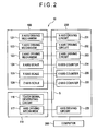
- Fig. 2 shows a block diagram of a major electrical control unit in the measurement system 10.
- the coordinate measuring machine 100 is equipped with an X axis driving mechanism 121, a Y axis driving mechanism 122 and a Z axis driving mechanism 123, those being driven by motors, and the X axis slider 106, the column 102 and the supporter 103, and the Z axis spindle 107 are driven by the respective driving mechanisms.
- the displacement of those sliders is detected by an X axis scale 124, a Y axis scale 125 and a Z axis scale 126, respectively.
- the controller 200 is equipped with an X axis driving circuit 201 that drives the motor of the X axis driving mechanism 121, a Y axis driving circuit 202 that drives the motor of the Y axis driving mechanism 122, and a Z axis driving circuit 203 that drives the motor of the Z axis driving mechanism 123.
- the scales of the axes of the coordinate measuring machine 100 are connected to an X axis counter 204, a Y axis counter 205 and a Z axis counter 206, respectively.
- each axis slider is counted by each of those axis counters and also counter values D (xi, yi and zi) of the axes are output as the measured data by a touch signal S generated in a touch signal generating circuit 116 of the touch signal probe 110.
- the touch signal probe 110 is equipped with an axis driving mechanism 117 as well as the touch signal generating circuit 116 and, as shown in Fig. 3, it is designed so that the axis 115 of the stylus 111 is tiltable in an arbitrary direction relative to the axis 114 of the probe body 113 of the touch signal probe 110.
- the axis driving mechanism 117 is composed of: a vertically tiltable driving mechanism that drives the axis 115 of the stylus 111 so as to tilt by an arbitrary angle ⁇ v to the axis 114 of the probe body 113; and a horizontally rotatable driving mechanism that drives the axis 115 of the stylus 111 so as to rotate by an arbitrary angle ⁇ h in a plane perpendicular to the axis 114 of the probe body 113.
- the axis driving mechanism 117 is driven by the axis driving circuit 225 of the controller 200.
- the computer 300 controls the three axis driving circuits 201 to 203 and the axis driving circuit 225 and also inputs the counter values D (xi, yi and zi) of the axes as measured tooth flank data Mi.
- the computer 300 is further equipped with various I/O devices (a keyboard, a mouse, a display, a printer, a circuit I/O device, an auxiliary memory, etc.), not shown in the figures, and makes it possible to do various I/O operations, the display and print of computed results and the like according to any purpose.
- I/O devices a keyboard, a mouse, a display, a printer, a circuit I/O device, an auxiliary memory, etc.
- Fig. 4 is a flowchart showing the procedure of the process in the case where a method for measuring a curved surface of a workpiece according to the present invention is carried out by the computer 300 and the procedure is hereunder explained by taking the case of measuring the tooth flank of a ring gear of a hypoid gear as the workpiece for instance.
- step S 10 the execution of the method for measuring a curved surface of a workpiece is started.
- step S20 basic parameters (for example, Fig. 21) and machine setting parameters (for example, Fig. 22) are input based on the design drawings and the like of a workpiece W (gear).
- the machine setting parameters may be replaced with theoretical values or values estimated from the results obtained by measuring an actual gear.
- a theoretical expression of the tooth flank of the gear is computed based on the basic parameters and the machine setting parameters.
- Xg, A (a coordinate transformation matrix related to rotation around an xm axis), Xgc (the position vector on a cutting blade edge), Dg (the position of the cutter center Oc in the coordinate system Om of a gear generator), and Ngc (a unit normal line on the cutting blade edge) are all vectors.
- u shows the rotating angle of a cutter 1 and v shows the distance from the cutter center Oc to the cutting blade edge.
- ⁇ gr shows a machine root angle (root cone angle) (refer to Fig. 25).
- the steps S20 and S30 compose the theoretical expression input steps.
- the theoretical expression is already known or when the shape expression is already derived from the analysis result of measured data, it is also acceptable to input directly the theoretical expression or the shape expression instead of the computation of the theoretical expression based on parameters such as designed values and the like and to use it as the theoretical expression at the succeeding steps.
- step S40 a measuring area is determined based on the theoretical expression.
- the tooth flank Xw of the workpiece W has a right flank Xw2 and a left flank Xw1 as shown in Fig. 6. Since these processing procedures of them are identical, the procedures in the case of measuring the left flank Xw1 are explained hereunder.
- a measuring area In the determination of a measuring area, one or more of measuring areas An are determined in a tooth flank area of the left flank Xw1.
- Various kinds of algorithms can be applied to this determination algorithm and in this case the measuring areas are determined by dividing the tooth flank equally in the tooth trace direction.
- Fig. 7 shows a tooth flank Xw1 and the measuring areas A1 and A2, divided into two equal pieces in the tooth trace direction, in which the left side of the drawing shows the inner side of the gear and the lower side thereof shows the root side of the tooth flank.
- step S50 the coordinate values and the normal vector at a representative point in each measuring area are computed.
- the algorithm of determining a representative point there are various methods. For example, it is a common practice to determine one point in the center of a measuring area in the case of measuring a tooth pitch, and one point each at the both ends of a measuring area, two points in total, in the case of measuring the shape of a tooth flank.
- the representative points Q11, Q12, Q21 and Q22 are determined at the both ends of the measuring areas A1 and A2 respectively at the center in the tooth depth direction of the tooth flank (the direction from the root to the tip of the tooth flank) and then coordinate values and the normal vector are computed for each representative point based on the theoretical expression.
- an internal angle ⁇ i formed at the intersection of the normal vectors N11 and N12 at the representative points Q11 and Q12 in the same measuring area is computed (refer to Fig. 8) and whether the internal angle ⁇ i is within a predetermined angle range or not is judged.
- the curvature of the tooth flank in the measuring area is judged to be small.
- the processing flow branches and goes to S80 and the axis angle of the stylus is determined.
- the curvature of the tooth flank in the measuring area is judged to be large. That is, if the measurement is executed in the measuring area with the same stylus axis angle ⁇ h without changing the stylus axis angle ⁇ h, it is judged that there arises the possibility of the interference between the workpiece W and the probe 110 and, in this case, the process flow branches and goes to S70 to divide the measuring area.
- Fig. 9 shows an example of the case where the measuring area A1 is divided into A11 and A12 by this method.
- step S70 After the measuring area is divided at step S70, the process flow returns to S50 and the coordinate values and the normal vector of the representative point in each measuring area are computed again.
- a tangent vector Tw is computed. If the teeth of a gear are not curving but straight as shown in Fig. 10 for example, assuming that the plane of the drawing is the horizontal plane, the axis angle ⁇ h of the stylus 111 in the horizontal plane is univocally determined in accordance with the tooth flank to be measured. In contrast, in the case of a spiral bevel gear, the tooth flank curves as shown in Fig. 6 for example and therefore it is necessary to determine an axis angle ⁇ h in accordance with the angle of the curvature of a measuring area.
- a tangent vector Tw in the tooth trace direction perpendicular to the normal vector Nw of the measuring area is determined, and the angle for parallelizing the plane that is tangent to a curved surface of a workpiece in the measuring area and also contains the tangent vector Tw (the plane perpendicular to the normal vector) and a plane that contains the axis 115 of the stylus 111 with each other is defined as the flank direction axis angle ⁇ h.
- a tangent vector may be determined by either method, the method of compounding the normal vectors of the representative points, computing a representative normal vector Nr of the measuring area, and determining a representative tangent vector Tr from this representative normal vector Nr (refer to Fig. 12), or the method of determining each tangent vector from each normal vector, compounding those tangent vectors, and then determining the representative tangent vector Tr (refer to Fig. 13), and the like.
- a slant axis angle ⁇ v (the axis angle in the tooth depth direction in the case of a bevel gear) is determined and this can be determined easily from the machine root angle ⁇ gr.
- the slant axis angle ⁇ v is determined based on the shape of the workpiece.
- the axis angles (the flank direction axis angle ⁇ h and the slant axis angle ⁇ v) are determined for each measuring area.
- the axis driving circuit 225 controls the axis driving mechanism 117 and the angles of the axis 115 of the stylus 111 are adjusted to ⁇ h and ⁇ v.
- the angles of the axis 115 of the stylus 111 are adjusted manually so as to be the angles ⁇ h and ⁇ v as indicated in a display.
- the measurement conditions include the kind of a probe 110 to be used (a touch signal probe/ a scanning probe), the maximum value/ control resolution of stylus axis angles ⁇ v and ⁇ h, whether or not a workpiece W is rotatably mounted on a rotary table, the diameter of a probe spherical contact tip 112, a retract distance (a distance from a workpiece W that allows the axis angles of a stylus 111 to change safely), kind of measurement (pitch measurement/ tooth flank shape measurement/ multiple tooth flank shape measurement), the number of tooth flanks to be measured, the direction of tooth flanks to be measured (right/ left), and the like.
- step S100 a measurement part program is generated.
- the measurement part program includes a stylus axis angle tuning command that tunes the axis angles of the stylus 111 by controlling the axis driving mechanism 117 via the axis driving circuit 225.
- a measurement part program conforming to the measuring probe is generated.
- the generated measurement part program is run by a measurement part program execution program (not shown in the figures) incorporated in the computer 300, the coordinate measuring machine 100 is controlled via the controller 200, and intended measured data are output from the controller 200.
- step S110 the determination of a workpiece coordinate system is executed, which is required when an actual workpiece W is mounted on the coordinate measuring machine 100.
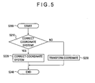
- step S 110 Detailed contents of the processing at step S 110 are shown in the flowchart of Fig. 5.
- the measurement part program generated at step S100 is generated by the theoretical coordinate system
- a workpiece coordinate system is determined. Since the workpiece coordinate system usually does not coincide with the theoretical coordinate system, it is necessary to conform the former coordinate system to the latter one or to transform the coordinate values of the measurement part program into the coordinate values of the workpiece.
- the conformation is executed at step S220.
- the coordinate transformation is executed at step S230.
- step S210 Those ramifications are carried out at step S210. Usually, an operator judges which case should be adopted.
- a workpiece coordinate system is once determined by temporarily adopting the coordinate system O of a coordinate measuring machine, thereafter one or more points of the workpiece W are subjected to measurement and, based on the result, the temporary workpiece coordinate system is corrected.
- the attitude of the workpiece W mounted on a measurement table 101 is not particularly regulated and, for simplicity, the explanations here are done on the premise that the workpiece W is a ring gear of a hypoid gear and it is mounted so that a reference plane Wb thereof abuts on the measurement table 101. Then, the configuration is determined so that the axis zg of the ring gear is parallel to the z axis of the coordinate measuring machine, the gear center Og is the origin point of the z axis of the coordinate measuring machine, and the axis zg of the ring gear takes the position of the origin point O of the x and y axes of the coordinate measuring machine.
- the position is identified at the height of pz so that the distance from the gear center on the xg-yg plane to the center position pg of the spherical contact tip 112 equals to Lt on the assumption that the spherical contact tip 112 is brought into contact with the theoretical tooth flank shown by the tooth flank expression (4) and the angle ⁇ g formed by the xg axis and the center position pg is computed.
- the direction of the straight line is defined as an xw axis (X axis of the workpiece coordinate system), a yw axis (Y axis of the workpiece coordinate system) that passes through the origin point O and is perpendicular to the xw axis is determined, and the Z axis is defined as a zw axis (Z axis of the workpiece coordinate system) as it is.
- the plural workpiece coordinate systems are identified, and the workpiece coordinate system Ow is determined by averaging the plural workpiece coordinate systems, a workpiece coordinate system with a higher degree of accuracy can be established.
- the coordinate transformation is carried out at step S230.
- the workpiece coordinate system is not rotated, the workpiece coordinate system is determined while the direction of the straight line O-p is regarded as the direction of the xw axis as it is, and the coordinate values and the axis angles of the measurement part program are rotated by an angle of - ⁇ g around the zg axis.
- Embodiment 2 is the case where the computer 300 of Embodiment 1 is replaced with a computer 400 and other configurations thereof are the same as Embodiment 1.
- Fig. 17 shows the block diagram of the computer 400.
- the coordinate system determination circuit 410 is composed of a coordinate system correction judgment circuit (the same operation as S210), a coordinate system correction circuit (the same operation as S220), and a coordinate transformation circuit (the same operation as S230).
- each circuit contains a memory circuit of a predetermined capacity in which various kinds of input data and computation results are stored according to need.
- the computer 400 is further equipped with various I/O devices (a keyboard, a mouse, a display, a printer, a circuit I/O device, an auxiliary memory, etc.), not shown in the figures, and makes it possible to do various operations, the display and print of computed results and the like according to any purpose.
- I/O devices a keyboard, a mouse, a display, a printer, a circuit I/O device, an auxiliary memory, etc.
- the measurement part program generated in the program generation circuit 409 is executed by a measurement part program execution circuit, not shown in the figures, of the computer 400, the coordinate measuring machine 100 is controlled via the controller 200, and intended measured data are output from the controller 200.
- the horizontally rotatable mechanism of a probe is controlled by the flank direction axis angle and the vertically tiltable driving mechanism of the probe is controlled by the slant axis angle.
- the modification is the same as Embodiment 1 except that the processing at steps S20 to S50 of the measurement method of Embodiment 1 (fig. 4) is modified.
- the steps of the modification corresponding to the steps of S20 to S50 in Embodiment 1 are defined as S20' to S50'.
- step S20' basic parameters (for example, Fig. 21) based on the design drawing (two-dimensional design drawing shown in Fig. 18) of a workpiece W (gear) and machine setting parameters (for example, Fig. 22) are input.
- the machine setting parameters the theoretical values or values estimated from the result obtained by measuring an actual gear may be used.
- step S30' the theoretical expression of a gear tooth flank is computed based on the basic parameters and the machine setting parameters.
- the theoretical expression can be computed by mechanistically describing the gear cutting process based on the theoretical or estimated machine setting parameters and, for example, the tooth flank expression Xg and the unit tooth flank normal line Ng of a ring gear of a hypoid gear are given by the expressions (4) and (5).
- Xg, A (a coordinate transformation matrix related to rotation around an xm axis), Xgc (the position vector on a cutting blade edge), Dg (the position of the cutter center Oc in the coordinate system Om of the gear generator), and Ngc (a unit normal line on the cutting blade edge) are all vectors.
- u shows the rotating angle of the cutter 1 and v shows the distance from the cutter center Oc to the cutting blade edge.
- ⁇ gr shows the machine root angle (root cone angle) (refer to Fig. 25).
- the origin point Og in the theoretical coordinate system of the gear shown in Fig. 25 is separate from the workpiece reference plane Wb by the distance Lg.
- the origin point Od since the origin point Od is located at the position of the workpiece reference plane Wb, the position of the zg axis of the theoretical coordinate system Og and that of the zd axis of the design coordinate system Od are conformed to each other but there exists an offset of the distance Lg.
- the xg axis of the theoretical coordinate system Og and the xd axis of the design coordinate system Od are parallel with each other and therefore the coordinate transformation from the design coordinate system Od (xd and zd) of the two-dimensional design drawing to the theoretical coordinate system (xg, yg and zg) of the three-dimensional theoretical expression may be executed by adding the value of offset - Lg (coordinate transformation parameter) to the zd axis coordinate of the design coordinate system Od.
- the points designated in the design coordinate system Od (xd and zd) of the two-dimensional design drawing correspond to the points on the xg-zg plane in the theoretical coordinate system (xg, yg and zg) of the three-dimensional theoretical expression.
- the measuring area is determined as a region including a representative point (for example, Q1) in the design coordinate system shown in Fig. 18.
- step S50' the three-dimensional coordinate values and the normal vector at the representative point in each measuring area are computed.
- the representative point can be determined by using the same algorithm as Embodiment 1.
- the assignment of the representative point is executed by assigning the measurement points (Q1, Q2, ..., Qn) on the two-dimensional design drawing of Fig. 18 and inputting the coordinate values (xd and zd).
- each of the assigned points (Q1, Q2, ..., Qn) is transformed into the xg-zg plane in the theoretical coordinate system Og by using the coordinate transformation parameter (refer to Fig. 19).
- the distance Li from an assigned point Qi to the origin point Og is determined and the position of the point Gi is searched so that the distance from the origin point Og to the point Gi shown by the theoretical tooth flank expression Xg may be equal to the distance Li.
- the three-dimensional coordinate values and the normal vector at the point Gi in the theoretical coordinate system are determined by the tooth flank expression Xg (expression (4)) and the unit tooth flank normal line Ng (expression (5)).
- the program generation in this modification is basically identical to the measurement part program generation (S 100) in Embodiment 1.
- the measurement points can be assigned based on the two-dimensional design drawing and, since the measurement conditions (the diameter of the spherical contact tip 112 of a measuring probe and the like) are already input, the measurement part program can be generated easily in the theoretical coordinate system Og based on those measurement conditions.
- a measurement part program conforming to the measuring probe is generated.
- the measuring probe When manual measurement is executed, after the determination of the coordinate system (S110), the measuring probe is slid manually, thus the spherical contact tip 112 is brought into contact with the workpiece surface to be measured, and, by the touch signal S generated at the time, the counter values D (xi, yi and zi) of each axis is input into the computer 300 as the measured data M.
- the computation of the assigned point is executed similarly to S50' of the modification, the point Gi in the theoretical coordinate system Og is searched, and the theoretical three-dimensional coordinate values at the point Gi are determined.
- the error between the measured data M and the theoretical three-dimensional coordinate values (equal to the coordinate values of the workpiece coordinate system Ow) at the measurement point is computed and the error is output.
- Embodiments 1 and 2 the cases where a coordinate measuring machine is used as the measuring machine are shown as the examples, but the present invention is not limited to the cases and is applicable to the cases where a surface texture measuring machine such as a surface roughness measuring machine, a contour measuring machine, a roundness measuring machine, a vision measuring machine or the like is used.
- a surface texture measuring machine such as a surface roughness measuring machine, a contour measuring machine, a roundness measuring machine, a vision measuring machine or the like is used.
- the processing procedures from S10 to S120 and from S200 to S240 can be incorporated into a program practicable by a computer and the program can be stored in a storage medium and supply to users.
- the program may be written by any language practicable by a computer, such as a machine language, an assembler language, an advanced computer language or the like.
- a form compiled by a compiler or an intermediate form executed by an interpreter is acceptable.
- the program may be provided not only by storing it in a storage medium such as a flexible disc, an MO disc, a DVD disc, a magnetic tape or the like but also via a wired or wireless telecommunication line including Internet.
Landscapes
- Physics & Mathematics (AREA)
- General Physics & Mathematics (AREA)
- A Measuring Device Byusing Mechanical Method (AREA)
- Length Measuring Devices With Unspecified Measuring Means (AREA)
Claims (20)
- Procédé de mesure d'une surface incurvée d'une pièce (W), comprenant :une étape de saisie d'une expression théorique pour obtenir une expression théorique de la pièce (W), dont la surface incurvée est mesurée avec une sonde de mesure (110) ayant un stylet (111) ;une étape de détermination d'une zone de mesure pour déterminer une zone de mesure sur la surface incurvée qui est une plage de mesure ;une étape de calcul d'un point représentatif pour définir un point représentatif dans la zone de mesure et calculer des valeurs de coordonnées et un vecteur normal du point représentatif sur la base de l'expression théorique ; etune étape de détermination d'un angle d'axe permettant de déterminer un angle d'axe du stylet (111) sur la base du vecteur normal,caractérisé en ce que l'étape de détermination de la zone de mesure comprend en outre la détermination d'un premier point terminal situé à une extrémité de la zone de mesure, et d'un second point terminal situé à une autre extrémité de la zone de mesure,le calcul de valeurs de coordonnées du premier point terminal, d'un vecteur normal de premier point terminal, de valeurs de coordonnées du second point terminal, et d'un vecteur normal de second point terminal sur la base de l'expression théorique, etla division de la zone de mesure lorsque l'angle interne formé par le premier vecteur normal et le second vecteur normal dépasse une plage angulaire prédéterminée, où l'étape de détermination de la zone de mesure est exécutée de manière répétée jusqu'à ce que l'angle interne fasse partie de la plage angulaire prédéterminée.
- Procédé de mesure de la surface incurvée d'une pièce (W) selon la revendication 1,
l'étape de saisie de l'expression théorique comprenant :une étape de saisie de paramètre pour saisir des paramètres de base de la pièce (W) ;
etune étape de calcul d'expression théorique pour calculer l'expression théorique de la pièce (W) sur la base des paramètres de base. - Procédé de mesure de la surface incurvée de la pièce (W) selon la revendication 1, dans lequel l'étape de détermination d'un angle d'axe calcule un vecteur tangentiel dans une direction de flanc dans la zone de mesure de la surface incurvée de la pièce (W) sur la base du vecteur normal du point représentatif, et détermine un angle d'axe de direction de flanc du stylet (111) sur la base du vecteur tangentiel.
- Procédé de mesure de la surface incurvée de la pièce (W) selon la revendication 3,
dans lequel l'étape de calcul de point représentatif comprend la détermination du premier point terminal situé à une extrémité de la zone de mesure et du second point terminal situé à l'autre extrémité de la zone de mesure, le calcul des valeurs de coordonnées du premier point terminal, du vecteur normal de premier point terminal, des valeurs de coordonnées du second point terminal, et du vecteur normal de second point terminal sur la base de l'expression théorique, et
dans lequel l'étape de détermination d'angle d'axe détermine l'angle d'axe de direction de flanc sur la base du vecteur tangentiel calculé à partir du vecteur normal de premier point terminal et du vecteur normal de second point terminal. - Procédé de mesure de la surface incurvée de la pièce (W) selon la revendication 4, dans lequel l'étape de détermination d'angle d'axe calcule un vecteur normal représentatif en combinant le premier vecteur normal et le second vecteur normal, calcule un vecteur tangentiel représentatif en tant que vecteur tangentiel sur la base du vecteur normal représentatif, et détermine l'angle d'axe de direction de flanc sur la base du vecteur tangentiel représentatif.
- Procédé de mesure de la surface incurvée de la pièce (W) selon la revendication 4, dans lequel l'étape de détermination d'angle d'axe calcule un premier vecteur tangentiel et un second vecteur tangentiel sur la base du premier vecteur normal et du second vecteur normal, et calcule le vecteur tangentiel sur la base du premier vecteur tangentiel et du second vecteur tangentiel afin de déterminer l'angle d'axe de direction de flanc.
- Procédé de mesure de la surface incurvée de la pièce (W) selon la revendication 1, dans lequel l'étape de détermination de la zone de mesure détermine un nombre prédéterminé de zones de mesure.
- Procédé de mesure de la surface incurvée de la pièce (W) selon l'une quelconque des revendications 4 à 7, dans lequel l'étape de division de la zone de mesure et l'étape de calcul d'un point représentatif sont exécutées de manière répétée jusqu'à ce que l'angle interne fasse partie de la plage angulaire prédéterminée, et
dans lequel l'étape de détermination d'angle d'axe détermine l'angle d'axe de direction de flanc pour chacune des zones de mesure divisées. - Procédé de mesure de la surface incurvée de la pièce (W) selon l'une quelconque des revendications 1 à 8, dans lequel l'étape de détermination d'angle d'axe détermine un angle d'axe d'inclinaison du stylet (111) sur la base d'une forme de la pièce dans la zone de mesure.
- Procédé de mesure de la surface incurvée de la pièce (W) selon l'une quelconque des revendications 1 à 9, comprenant en outre :une étape de saisie de conditions permettant de saisir des conditions de mesure comprenant des informations relatives à une machine de mesure ; etune étape de génération de programme permettant de générer un programme de partie de mesure destiné à mesurer la pièce (W) sur la base de l'expression théorique.
- Procédé de mesure de la surface incurvée de la pièce (W) selon la revendication 10, dans lequel le programme de partie de mesure contient une commande de réglage de l'angle du stylet (111) par rapport à l'angle d'axe.
- Procédé de mesure de la surface incurvée de la pièce (W) selon l'une quelconque des revendications 1 à 11, comprenant en outre une étape de détermination d'un système de coordonnées permettant de déterminer un système de coordonnées de la pièce sur la base d'une attitude de la pièce (W) montée sur la machine de mesure.
- Procédé de mesure de la surface incurvée de la pièce (W) selon la revendication 12, dans lequel l'étape de détermination d'un système de coordonnées comprend en outre une étape de correction d'un système de coordonnées permettant de conformer le système de coordonnées de la pièce avec un système de coordonnées théorique de l'expression théorique.
- Procédé de mesure de la surface incurvée de la pièce (W) selon la revendication 12, dans lequel l'étape de détermination d'un système de coordonnées comprend en outre, lorsque le système de coordonnées de la pièce et le système de coordonnées théorique de l'expression théorique ne se conforment pas, une étape de transformation de coordonnées permettant de transformer les valeurs de coordonnées et l'angle d'axe indiqués dans le système de coordonnées- théorique en valeurs de coordonnées et un angle d'axe indiqués dans le système de coordonnées de la pièce.
- Procédé de mesure de la surface incurvée de la pièce (W) selon la revendication 1,
l'étape de saisie d'une expression théorique comprenant :une étape de saisie de paramètres pour saisir des paramètres de base sur la base d'un schéma en deux dimensions de la pièce (W) ; etune étape de calcul d'expression théorique pour calculer une expression théorique en trois dimensions de la pièce (W) sur la base des paramètres de base, où l'étape de calcul d'un point représentatif détermine le point représentatif par une coordonnée en deux dimensions sur la base du schéma en deux dimensions, et calcule des valeurs de coordonnées en trois dimensions et un vecteur normal du point représentatif sur la base de l'expression théorique en trois dimensions. - Procédé de mesure de la surface incurvée de la pièce (W) selon la revendication 15, comprenant en outre une étape de calcul de paramètre de transformation de coordonnées pour calculer un paramètre de transformation de coordonnées entre un système de coordonnées du schéma en deux dimensions et un système de coordonnées théorique de l'expression théorique en trois dimensions.
- Procédé de mesure de la surface incurvée de la pièce (W) selon l'une quelconque des revendications 1 à 16, dans lequel la sonde de mesure (110) est soit une sonde à signal tactile, soit une sonde de mesure à balayage.
- Procédé de mesure de la surface incurvée de la pièce (W) selon l'une quelconque des revendications 1 à 17, dans lequel la pièce (W) est un engrenage biseauté en spirale.
- Programme permettant à un ordinateur d'exécuter le procédé de mesure d'une surface incurvée de la pièce (W) selon l'une quelconque des revendications 1 à 18 afin de mesurer la pièce (W).
- Support stockant le programme selon la revendication 19.
Applications Claiming Priority (4)
| Application Number | Priority Date | Filing Date | Title |
|---|---|---|---|
| JP2003358637 | 2003-10-20 | ||
| JP2003358637A JP4322087B2 (ja) | 2003-10-20 | 2003-10-20 | ワーク曲面の測定方法とそのプログラムおよび媒体 |
| JP2003358636 | 2003-10-20 | ||
| JP2003358636A JP2005122580A (ja) | 2003-10-20 | 2003-10-20 | ワーク曲面の計算方法とそのプログラムおよび媒体 |
Publications (3)
| Publication Number | Publication Date |
|---|---|
| EP1526356A2 EP1526356A2 (fr) | 2005-04-27 |
| EP1526356A3 EP1526356A3 (fr) | 2006-02-01 |
| EP1526356B1 true EP1526356B1 (fr) | 2007-12-12 |
Family
ID=34395663
Family Applications (1)
| Application Number | Title | Priority Date | Filing Date |
|---|---|---|---|
| EP04024863A Expired - Lifetime EP1526356B1 (fr) | 2003-10-20 | 2004-10-19 | Procédé pour mesurer la surface courbée d'un objet |
Country Status (4)
| Country | Link |
|---|---|
| US (1) | US7251580B2 (fr) |
| EP (1) | EP1526356B1 (fr) |
| CN (1) | CN1609552B (fr) |
| DE (1) | DE602004010599T2 (fr) |
Cited By (1)
| Publication number | Priority date | Publication date | Assignee | Title |
|---|---|---|---|---|
| KR100952360B1 (ko) * | 2008-10-13 | 2010-04-09 | 류만열 | 곡면 측정방법 |
Families Citing this family (34)
| Publication number | Priority date | Publication date | Assignee | Title |
|---|---|---|---|---|
| JP4593142B2 (ja) * | 2003-09-25 | 2010-12-08 | ハイデルベルガー ドルツクマシーネン アクチエンゲゼルシヤフト | 被加工物をコンピュータ制御で製造するシステムおよび製造される被加工物を測定する方法 |
| JP4417121B2 (ja) * | 2004-01-19 | 2010-02-17 | 株式会社ミツトヨ | 被測定物の通り出し方法、及び表面性状測定装置 |
| JP4634867B2 (ja) * | 2005-06-03 | 2011-02-16 | 株式会社ミツトヨ | 画像測定システム及び方法 |
| GB0518153D0 (en) * | 2005-09-07 | 2005-10-12 | Rolls Royce Plc | Apparatus for measuring wall thicknesses of objects |
| CN100437445C (zh) * | 2005-12-23 | 2008-11-26 | 鸿富锦精密工业(深圳)有限公司 | 三次元离线碰撞检测系统及方法 |
| JP5301412B2 (ja) * | 2009-10-21 | 2013-09-25 | 株式会社ミツトヨ | 測定力制御装置 |
| KR100994741B1 (ko) | 2010-05-04 | 2010-11-16 | 주식회사 덕인 | 3차원 측정기를 이용하여 측정 대상의 곡률에 따라 측정 간격을 자동으로 조절하여 미지의 곡선을 측정하는 방법 |
| DE102010023728A1 (de) * | 2010-06-14 | 2011-12-15 | Liebherr-Verzahntechnik Gmbh | Verfahren zum Herstellen einer Mehrzahl von identischen Zahnrädern mittles abspanender Bearbeitung |
| WO2012037059A1 (fr) * | 2010-09-13 | 2012-03-22 | Hexagon Technology Center Gmbh | Procédé et appareil pour commander une machine de mesure de coordonnées à balayage de surface |
| CN102519408B (zh) * | 2011-12-12 | 2013-09-11 | 陕西宝成航空仪表有限责任公司 | 用三坐标测量机一次测量多个零件的方法 |
| EP2820377B1 (fr) * | 2012-02-27 | 2020-04-01 | Taylor Hobson Limited | Processeur de données pour un appareil métrologique pour la mesure d'une caractéristique de surface et méthode de mesure correspondante |
| CN103292729A (zh) * | 2013-05-16 | 2013-09-11 | 厦门大学 | 一种非球面法向误差检测装置 |
| CN103438800B (zh) * | 2013-08-29 | 2016-04-06 | 厦门大学 | 用于大口径光学元件精密检测平台的空间误差计算方法 |
| US20150178484A1 (en) | 2013-12-20 | 2015-06-25 | Mitutoyo Corporation | Remote Accessory Management in a Programming Environment for a Progammable Metrology System |
| US9606525B2 (en) | 2013-12-23 | 2017-03-28 | Mitutoyo Corporation | Remote accessory for generating customized and synchronized reference notes for a programmable metrology system |
| DE102014112396B4 (de) * | 2014-08-28 | 2022-01-13 | Carl Zeiss Industrielle Messtechnik Gmbh | Verfahren zur Einzelpunktantastung eines Werkstücks und Koordinatenmessgerät |
| US10545019B2 (en) * | 2015-04-14 | 2020-01-28 | Hexagon Metrology, Inc. | CMM probe path controller and method |
| US9752860B2 (en) | 2015-07-14 | 2017-09-05 | Caterpillar Inc. | System and method for gear measurement |
| CN105631424B (zh) * | 2015-12-31 | 2019-05-10 | 山东省计算中心(国家超级计算济南中心) | 工件识别方法 |
| JP6206527B2 (ja) * | 2016-03-16 | 2017-10-04 | 横浜ゴム株式会社 | 円形部材の内周長測定装置 |
| DE102016107255B4 (de) * | 2016-04-19 | 2019-09-05 | Carl Zeiss Industrielle Messtechnik Gmbh | Drehtisch für eine Koordinatenmessmaschine mit einer Arretiervorrichtung, Koordinatenmessmaschine und Verfahren zum Betrieb |
| JP6464209B2 (ja) * | 2017-01-27 | 2019-02-06 | ファナック株式会社 | 数値制御装置 |
| CN107570983B (zh) * | 2017-09-05 | 2019-06-14 | 西北工业大学 | 一种曲面零件自动装配的方法及系统 |
| CN107588715B (zh) * | 2017-10-30 | 2023-08-22 | 合肥工业大学 | 一种基于磁效应的空间位置检测装置及测量方法 |
| CN108286937B (zh) * | 2018-01-30 | 2020-03-24 | 京东方科技集团股份有限公司 | 接触式扫描测头、坐标测量装置、系统及方法 |
| CN108775883B (zh) * | 2018-06-30 | 2020-06-02 | 北京动力机械研究所 | 一种叶轮类零件快速换装精度在线检测方法 |
| CN109408936B (zh) * | 2018-10-17 | 2022-12-09 | 湖北三江航天江北机械工程有限公司 | 滑翔天线罩深盲型腔加工及在线测量方法 |
| JP7257942B2 (ja) * | 2019-11-29 | 2023-04-14 | 日立Astemo株式会社 | 表面検査装置および形状矯正装置、並びに表面検査方法および形状矯正方法 |
| CN112388257B (zh) * | 2020-11-10 | 2022-04-12 | 哈尔滨电气动力装备有限公司 | 屏蔽电机导轴瓦支撑块加工工艺 |
| CN114184156B (zh) * | 2021-12-01 | 2024-01-16 | 中国第一汽车股份有限公司 | 一种驱动桥准双曲面锥齿轮的测绘方法 |
| CN115194260B (zh) * | 2022-07-11 | 2025-04-18 | 重庆大学 | 基于数控蜗杆砂轮磨齿机的面齿轮齿距误差在机测量方法 |
| CN117537736A (zh) * | 2023-10-26 | 2024-02-09 | 中国航发沈阳黎明航空发动机有限责任公司 | 一种高压双层整体叶盘叶型测量方法 |
| CN118999441B (zh) * | 2024-03-29 | 2025-10-28 | 西安工业大学 | 一种大基圆半径渐开线的量值溯源方法 |
| CN118456116B (zh) * | 2024-07-15 | 2024-09-20 | 中国航发贵州黎阳航空动力有限公司 | 涡轮盘燕尾型榫槽角向的在线找正方法 |
Family Cites Families (10)
| Publication number | Priority date | Publication date | Assignee | Title |
|---|---|---|---|---|
| US4166323A (en) * | 1973-09-14 | 1979-09-04 | Maag Gear-Wheel & Machine Co. Ltd. | Gear tester for profile and lead testing |
| CH658126A5 (de) * | 1983-03-07 | 1986-10-15 | Maag Zahnraeder & Maschinen Ag | Messgeraet und -verfahren zur teilungspruefung von zahnraedern. |
| GB2202659B (en) * | 1987-02-23 | 1991-07-17 | Mitutoyo Corp | Coordinate measuring instrument and method of generating pattern data concerning shape of work to be measured |
| US5271271A (en) * | 1991-04-03 | 1993-12-21 | Frazier Charles H | Method and apparatus for inspection of gears |
| US5547439A (en) * | 1994-03-22 | 1996-08-20 | Stairmaster Sports/Medical Products, Inc. | Exercise system |
| DE19712029A1 (de) * | 1997-03-21 | 1998-09-24 | Zeiss Carl Fa | Verfahren zur Steuerung von Koordinatenmeßgeräten nach Solldaten |
| DE19821371A1 (de) | 1998-05-13 | 1999-11-18 | Zeiss Carl Fa | Verfahren zur Steuerung eines Koordinatenmeßgerätes und Koordinatenmeßgerät |
| EP1330686B1 (fr) | 2000-09-15 | 2006-12-27 | Werth Messtechnik GmbH | Procede pour generer un programme de mesure destine a un appareil de mesure de coordonnees |
| DE10131160A1 (de) | 2001-06-29 | 2003-01-16 | Zeiss Carl | Verfahren zum Betreiben eines Koordinatenmessgeräts mit einem Dreh-Schwenk-Gelenk |
| EP1320000B1 (fr) * | 2001-12-12 | 2007-05-23 | Tesa Sa | Méthode de calibrage d'une machine à mesurer |
-
2004
- 2004-10-14 US US10/965,335 patent/US7251580B2/en not_active Expired - Lifetime
- 2004-10-19 DE DE602004010599T patent/DE602004010599T2/de not_active Expired - Lifetime
- 2004-10-19 CN CN2004100837652A patent/CN1609552B/zh not_active Expired - Fee Related
- 2004-10-19 EP EP04024863A patent/EP1526356B1/fr not_active Expired - Lifetime
Cited By (1)
| Publication number | Priority date | Publication date | Assignee | Title |
|---|---|---|---|---|
| KR100952360B1 (ko) * | 2008-10-13 | 2010-04-09 | 류만열 | 곡면 측정방법 |
Also Published As
| Publication number | Publication date |
|---|---|
| CN1609552A (zh) | 2005-04-27 |
| DE602004010599D1 (de) | 2008-01-24 |
| US7251580B2 (en) | 2007-07-31 |
| EP1526356A3 (fr) | 2006-02-01 |
| DE602004010599T2 (de) | 2008-12-04 |
| EP1526356A2 (fr) | 2005-04-27 |
| US20050086025A1 (en) | 2005-04-21 |
| CN1609552B (zh) | 2010-05-05 |
Similar Documents
| Publication | Publication Date | Title |
|---|---|---|
| EP1526356B1 (fr) | Procédé pour mesurer la surface courbée d'un objet | |
| KR101130596B1 (ko) | 기상 계측 장치의 프로브 장착 위치 산출 방법 | |
| US20130282328A1 (en) | Error measurment device and error measurement method | |
| He et al. | An improved adaptive sampling strategy for freeform surface inspection on CMM | |
| EP1698954B1 (fr) | Procédé d'étalonnage d'un mécanisme cinétique parallèle | |
| JP5665270B2 (ja) | 工作物の表面を走査する方法 | |
| JP6942577B2 (ja) | 工作機械の数値制御装置及び数値制御方法 | |
| JP5189806B2 (ja) | 表面形状測定装置 | |
| EP1579168B2 (fr) | Procede d'examen d'une piece et dispositif | |
| Cho et al. | Integrated error compensation method using OMM system for profile milling operation | |
| JP3527565B2 (ja) | 歯車計測方法及びnc歯車加工機 | |
| JP2003500675A (ja) | 計測機器による移動制御 | |
| CN112417537B (zh) | 一种基于车削加工将几何误差可视化的表面形貌仿真方法 | |
| JP2012030338A (ja) | 多軸工作機械の幾何誤差の計測方法 | |
| EP4231103A1 (fr) | Système et procédé d'usinage d'un composant | |
| JP4322087B2 (ja) | ワーク曲面の測定方法とそのプログラムおよび媒体 | |
| JP3634146B2 (ja) | 砥石整形誤差補正方法及び砥石整形・直溝成形研削加工誤差補正方法並びにそれらの誤差補正装置 | |
| EP3101380B1 (fr) | Procédé de commande d'appareil de mesure de forme | |
| JPS63302310A (ja) | 座標測定機の測定ボリューム内の点の絶対位置を決定する方法および装置 | |
| US5373220A (en) | Numerical control device for driving non-orthogonal mechanical axes | |
| JP5374048B2 (ja) | ウォームのシミュレーション研削方法及びウォーム研削システム | |
| CN113385984A (zh) | 一种刀具径向跳动识别方法、装置、终端及存储介质 | |
| JP2002005654A (ja) | かさ歯車の歯面誤差測定方法 | |
| US20250028296A1 (en) | Computation device, machining system, and correction method | |
| JP7769171B1 (ja) | 情報処理装置および情報処理方法 |
Legal Events
| Date | Code | Title | Description |
|---|---|---|---|
| PUAI | Public reference made under article 153(3) epc to a published international application that has entered the european phase |
Free format text: ORIGINAL CODE: 0009012 |
|
| AK | Designated contracting states |
Kind code of ref document: A2 Designated state(s): AT BE BG CH CY CZ DE DK EE ES FI FR GB GR HU IE IT LI LU MC NL PL PT RO SE SI SK TR |
|
| AX | Request for extension of the european patent |
Extension state: AL HR LT LV MK |
|
| PUAL | Search report despatched |
Free format text: ORIGINAL CODE: 0009013 |
|
| AK | Designated contracting states |
Kind code of ref document: A3 Designated state(s): AT BE BG CH CY CZ DE DK EE ES FI FR GB GR HU IE IT LI LU MC NL PL PT RO SE SI SK TR |
|
| AX | Request for extension of the european patent |
Extension state: AL HR LT LV MK |
|
| RIC1 | Information provided on ipc code assigned before grant |
Ipc: G01B 21/04 20060101AFI20050203BHEP Ipc: G05B 19/401 20060101ALI20051214BHEP |
|
| 17P | Request for examination filed |
Effective date: 20060629 |
|
| 17Q | First examination report despatched |
Effective date: 20060831 |
|
| AKX | Designation fees paid |
Designated state(s): DE FR GB IT |
|
| 17Q | First examination report despatched |
Effective date: 20060831 |
|
| GRAP | Despatch of communication of intention to grant a patent |
Free format text: ORIGINAL CODE: EPIDOSNIGR1 |
|
| GRAS | Grant fee paid |
Free format text: ORIGINAL CODE: EPIDOSNIGR3 |
|
| GRAA | (expected) grant |
Free format text: ORIGINAL CODE: 0009210 |
|
| AK | Designated contracting states |
Kind code of ref document: B1 Designated state(s): DE FR GB IT |
|
| REG | Reference to a national code |
Ref country code: GB Ref legal event code: FG4D |
|
| REF | Corresponds to: |
Ref document number: 602004010599 Country of ref document: DE Date of ref document: 20080124 Kind code of ref document: P |
|
| ET | Fr: translation filed | ||
| PLBE | No opposition filed within time limit |
Free format text: ORIGINAL CODE: 0009261 |
|
| STAA | Information on the status of an ep patent application or granted ep patent |
Free format text: STATUS: NO OPPOSITION FILED WITHIN TIME LIMIT |
|
| 26N | No opposition filed |
Effective date: 20080915 |
|
| PG25 | Lapsed in a contracting state [announced via postgrant information from national office to epo] |
Ref country code: IT Free format text: LAPSE BECAUSE OF NON-PAYMENT OF DUE FEES Effective date: 20081031 |
|
| REG | Reference to a national code |
Ref country code: FR Ref legal event code: PLFP Year of fee payment: 12 |
|
| REG | Reference to a national code |
Ref country code: FR Ref legal event code: PLFP Year of fee payment: 13 |
|
| REG | Reference to a national code |
Ref country code: FR Ref legal event code: PLFP Year of fee payment: 14 |
|
| REG | Reference to a national code |
Ref country code: FR Ref legal event code: PLFP Year of fee payment: 15 |
|
| PGFP | Annual fee paid to national office [announced via postgrant information from national office to epo] |
Ref country code: DE Payment date: 20191021 Year of fee payment: 16 |
|
| PGFP | Annual fee paid to national office [announced via postgrant information from national office to epo] |
Ref country code: FR Payment date: 20191028 Year of fee payment: 16 |
|
| PGFP | Annual fee paid to national office [announced via postgrant information from national office to epo] |
Ref country code: GB Payment date: 20191021 Year of fee payment: 16 |
|
| REG | Reference to a national code |
Ref country code: DE Ref legal event code: R119 Ref document number: 602004010599 Country of ref document: DE |
|
| GBPC | Gb: european patent ceased through non-payment of renewal fee |
Effective date: 20201019 |
|
| PG25 | Lapsed in a contracting state [announced via postgrant information from national office to epo] |
Ref country code: DE Free format text: LAPSE BECAUSE OF NON-PAYMENT OF DUE FEES Effective date: 20210501 Ref country code: FR Free format text: LAPSE BECAUSE OF NON-PAYMENT OF DUE FEES Effective date: 20201031 |
|
| PG25 | Lapsed in a contracting state [announced via postgrant information from national office to epo] |
Ref country code: GB Free format text: LAPSE BECAUSE OF NON-PAYMENT OF DUE FEES Effective date: 20201019 |