EP1526343A2 - Installation de climatisation avec dispositif d'humidification/déshumidification - Google Patents
Installation de climatisation avec dispositif d'humidification/déshumidification Download PDFInfo
- Publication number
- EP1526343A2 EP1526343A2 EP05001543A EP05001543A EP1526343A2 EP 1526343 A2 EP1526343 A2 EP 1526343A2 EP 05001543 A EP05001543 A EP 05001543A EP 05001543 A EP05001543 A EP 05001543A EP 1526343 A2 EP1526343 A2 EP 1526343A2
- Authority
- EP
- European Patent Office
- Prior art keywords
- air
- duct
- moisture absorbing
- indoor
- room
- Prior art date
- Legal status (The legal status is an assumption and is not a legal conclusion. Google has not performed a legal analysis and makes no representation as to the accuracy of the status listed.)
- Withdrawn
Links
Images


Classifications
-
- F—MECHANICAL ENGINEERING; LIGHTING; HEATING; WEAPONS; BLASTING
- F24—HEATING; RANGES; VENTILATING
- F24F—AIR-CONDITIONING; AIR-HUMIDIFICATION; VENTILATION; USE OF AIR CURRENTS FOR SCREENING
- F24F3/00—Air-conditioning systems in which conditioned primary air is supplied from one or more central stations to distributing units in the rooms or spaces where it may receive secondary treatment; Apparatus specially designed for such systems
- F24F3/12—Air-conditioning systems in which conditioned primary air is supplied from one or more central stations to distributing units in the rooms or spaces where it may receive secondary treatment; Apparatus specially designed for such systems characterised by the treatment of the air otherwise than by heating and cooling
- F24F3/14—Air-conditioning systems in which conditioned primary air is supplied from one or more central stations to distributing units in the rooms or spaces where it may receive secondary treatment; Apparatus specially designed for such systems characterised by the treatment of the air otherwise than by heating and cooling by humidification; by dehumidification
- F24F3/1411—Air-conditioning systems in which conditioned primary air is supplied from one or more central stations to distributing units in the rooms or spaces where it may receive secondary treatment; Apparatus specially designed for such systems characterised by the treatment of the air otherwise than by heating and cooling by humidification; by dehumidification by absorbing or adsorbing water, e.g. using an hygroscopic desiccant
- F24F3/1423—Air-conditioning systems in which conditioned primary air is supplied from one or more central stations to distributing units in the rooms or spaces where it may receive secondary treatment; Apparatus specially designed for such systems characterised by the treatment of the air otherwise than by heating and cooling by humidification; by dehumidification by absorbing or adsorbing water, e.g. using an hygroscopic desiccant with a moving bed of solid desiccants, e.g. a rotary wheel supporting solid desiccants
-
- F—MECHANICAL ENGINEERING; LIGHTING; HEATING; WEAPONS; BLASTING
- F24—HEATING; RANGES; VENTILATING
- F24F—AIR-CONDITIONING; AIR-HUMIDIFICATION; VENTILATION; USE OF AIR CURRENTS FOR SCREENING
- F24F1/00—Room units for air-conditioning, e.g. separate or self-contained units or units receiving primary air from a central station
- F24F1/0007—Indoor units, e.g. fan coil units
- F24F1/0043—Indoor units, e.g. fan coil units characterised by mounting arrangements
- F24F1/0057—Indoor units, e.g. fan coil units characterised by mounting arrangements mounted in or on a wall
-
- F—MECHANICAL ENGINEERING; LIGHTING; HEATING; WEAPONS; BLASTING
- F24—HEATING; RANGES; VENTILATING
- F24F—AIR-CONDITIONING; AIR-HUMIDIFICATION; VENTILATION; USE OF AIR CURRENTS FOR SCREENING
- F24F1/00—Room units for air-conditioning, e.g. separate or self-contained units or units receiving primary air from a central station
- F24F1/0007—Indoor units, e.g. fan coil units
- F24F1/0059—Indoor units, e.g. fan coil units characterised by heat exchangers
- F24F1/0063—Indoor units, e.g. fan coil units characterised by heat exchangers by the mounting or arrangement of the heat exchangers
-
- F—MECHANICAL ENGINEERING; LIGHTING; HEATING; WEAPONS; BLASTING
- F24—HEATING; RANGES; VENTILATING
- F24F—AIR-CONDITIONING; AIR-HUMIDIFICATION; VENTILATION; USE OF AIR CURRENTS FOR SCREENING
- F24F1/00—Room units for air-conditioning, e.g. separate or self-contained units or units receiving primary air from a central station
- F24F1/06—Separate outdoor units, e.g. outdoor unit to be linked to a separate room comprising a compressor and a heat exchanger
- F24F1/26—Refrigerant piping
- F24F1/32—Refrigerant piping for connecting the separate outdoor units to indoor units
-
- F—MECHANICAL ENGINEERING; LIGHTING; HEATING; WEAPONS; BLASTING
- F24—HEATING; RANGES; VENTILATING
- F24F—AIR-CONDITIONING; AIR-HUMIDIFICATION; VENTILATION; USE OF AIR CURRENTS FOR SCREENING
- F24F11/00—Control or safety arrangements
- F24F11/30—Control or safety arrangements for purposes related to the operation of the system, e.g. for safety or monitoring
-
- F—MECHANICAL ENGINEERING; LIGHTING; HEATING; WEAPONS; BLASTING
- F24—HEATING; RANGES; VENTILATING
- F24F—AIR-CONDITIONING; AIR-HUMIDIFICATION; VENTILATION; USE OF AIR CURRENTS FOR SCREENING
- F24F11/00—Control or safety arrangements
- F24F11/50—Control or safety arrangements characterised by user interfaces or communication
- F24F11/52—Indication arrangements, e.g. displays
-
- F—MECHANICAL ENGINEERING; LIGHTING; HEATING; WEAPONS; BLASTING
- F24—HEATING; RANGES; VENTILATING
- F24F—AIR-CONDITIONING; AIR-HUMIDIFICATION; VENTILATION; USE OF AIR CURRENTS FOR SCREENING
- F24F11/00—Control or safety arrangements
- F24F11/50—Control or safety arrangements characterised by user interfaces or communication
- F24F11/56—Remote control
-
- F—MECHANICAL ENGINEERING; LIGHTING; HEATING; WEAPONS; BLASTING
- F24—HEATING; RANGES; VENTILATING
- F24F—AIR-CONDITIONING; AIR-HUMIDIFICATION; VENTILATION; USE OF AIR CURRENTS FOR SCREENING
- F24F3/00—Air-conditioning systems in which conditioned primary air is supplied from one or more central stations to distributing units in the rooms or spaces where it may receive secondary treatment; Apparatus specially designed for such systems
- F24F3/12—Air-conditioning systems in which conditioned primary air is supplied from one or more central stations to distributing units in the rooms or spaces where it may receive secondary treatment; Apparatus specially designed for such systems characterised by the treatment of the air otherwise than by heating and cooling
- F24F3/14—Air-conditioning systems in which conditioned primary air is supplied from one or more central stations to distributing units in the rooms or spaces where it may receive secondary treatment; Apparatus specially designed for such systems characterised by the treatment of the air otherwise than by heating and cooling by humidification; by dehumidification
- F24F2003/1458—Air-conditioning systems in which conditioned primary air is supplied from one or more central stations to distributing units in the rooms or spaces where it may receive secondary treatment; Apparatus specially designed for such systems characterised by the treatment of the air otherwise than by heating and cooling by humidification; by dehumidification using regenerators
- F24F2003/1464—Air-conditioning systems in which conditioned primary air is supplied from one or more central stations to distributing units in the rooms or spaces where it may receive secondary treatment; Apparatus specially designed for such systems characterised by the treatment of the air otherwise than by heating and cooling by humidification; by dehumidification using regenerators using rotating regenerators
-
- F—MECHANICAL ENGINEERING; LIGHTING; HEATING; WEAPONS; BLASTING
- F24—HEATING; RANGES; VENTILATING
- F24F—AIR-CONDITIONING; AIR-HUMIDIFICATION; VENTILATION; USE OF AIR CURRENTS FOR SCREENING
- F24F2203/00—Devices or apparatus used for air treatment
- F24F2203/10—Rotary wheel
- F24F2203/1012—Details of the casing or cover
-
- F—MECHANICAL ENGINEERING; LIGHTING; HEATING; WEAPONS; BLASTING
- F24—HEATING; RANGES; VENTILATING
- F24F—AIR-CONDITIONING; AIR-HUMIDIFICATION; VENTILATION; USE OF AIR CURRENTS FOR SCREENING
- F24F2203/00—Devices or apparatus used for air treatment
- F24F2203/10—Rotary wheel
- F24F2203/1016—Rotary wheel combined with another type of cooling principle, e.g. compression cycle
-
- F—MECHANICAL ENGINEERING; LIGHTING; HEATING; WEAPONS; BLASTING
- F24—HEATING; RANGES; VENTILATING
- F24F—AIR-CONDITIONING; AIR-HUMIDIFICATION; VENTILATION; USE OF AIR CURRENTS FOR SCREENING
- F24F2203/00—Devices or apparatus used for air treatment
- F24F2203/10—Rotary wheel
- F24F2203/1032—Desiccant wheel
-
- F—MECHANICAL ENGINEERING; LIGHTING; HEATING; WEAPONS; BLASTING
- F24—HEATING; RANGES; VENTILATING
- F24F—AIR-CONDITIONING; AIR-HUMIDIFICATION; VENTILATION; USE OF AIR CURRENTS FOR SCREENING
- F24F2203/00—Devices or apparatus used for air treatment
- F24F2203/10—Rotary wheel
- F24F2203/1056—Rotary wheel comprising a reheater
-
- F—MECHANICAL ENGINEERING; LIGHTING; HEATING; WEAPONS; BLASTING
- F24—HEATING; RANGES; VENTILATING
- F24F—AIR-CONDITIONING; AIR-HUMIDIFICATION; VENTILATION; USE OF AIR CURRENTS FOR SCREENING
- F24F2203/00—Devices or apparatus used for air treatment
- F24F2203/10—Rotary wheel
- F24F2203/1068—Rotary wheel comprising one rotor
-
- F—MECHANICAL ENGINEERING; LIGHTING; HEATING; WEAPONS; BLASTING
- F24—HEATING; RANGES; VENTILATING
- F24F—AIR-CONDITIONING; AIR-HUMIDIFICATION; VENTILATION; USE OF AIR CURRENTS FOR SCREENING
- F24F2203/00—Devices or apparatus used for air treatment
- F24F2203/10—Rotary wheel
- F24F2203/1084—Rotary wheel comprising two flow rotor segments
-
- F—MECHANICAL ENGINEERING; LIGHTING; HEATING; WEAPONS; BLASTING
- F24—HEATING; RANGES; VENTILATING
- F24F—AIR-CONDITIONING; AIR-HUMIDIFICATION; VENTILATION; USE OF AIR CURRENTS FOR SCREENING
- F24F2203/00—Devices or apparatus used for air treatment
- F24F2203/10—Rotary wheel
- F24F2203/1088—Rotary wheel comprising three flow rotor segments
-
- F—MECHANICAL ENGINEERING; LIGHTING; HEATING; WEAPONS; BLASTING
- F24—HEATING; RANGES; VENTILATING
- F24F—AIR-CONDITIONING; AIR-HUMIDIFICATION; VENTILATION; USE OF AIR CURRENTS FOR SCREENING
- F24F2203/00—Devices or apparatus used for air treatment
- F24F2203/10—Rotary wheel
- F24F2203/1092—Rotary wheel comprising four flow rotor segments
Definitions
- the present invention relates to an air conditioner in which a decrease in circulation efficiency of the air passing through a ventilation duct can be prevented.
- Some of the indoor units of air conditioners have a display apparatus.
- a display apparatus 104 is arranged on the right side of an inlet 103 of a body 102 of an indoor unit 101.
- a liquid crystal display is employed which has an overall display portion enlarged to be easier viewable, on which an operation mode, a state of operation and the like are displayed.
- the liquid crystal display apparatus is provided on a lower right side of the indoor unit. Though convenience of use is considered, by displaying a state of operation and temperature and moisture inside and outside of the room, it is still necessary to increase the area when the contents to be displayed on the liquid crystal display apparatus are to be added. Therefore, as long as the apparatus is on the present position, the size of the liquid crystal display apparatus is disadvantageously limited or the width of the body must be increased.
- a humidifying/dehumidifying apparatus attached to an indoor unit of a conventional air conditioner will be described.
- a recovery fan 202 and a motor mounting plate on which a motor is fixed are mounted by screws at prescribed positions, and a moisture absorbing rotor 203 is fitted on a shaft portion of case L201, with an outer peripheral gear side facing the case L202.
- a driving motor 204 and a reduction gear 205 of moisture absorbing rotor 203 are also attached at prescribed positions.
- a case R208 having a metal cover 207 incorporating a recovery heater 206 incorporated at a prescribed position is combined with case L201 and fixed by a screw.
- Moisture absorbing rotor 203 is an absorber consisting of a number of cylindrical ceramic members and having a substance absorbing moisture in the air applied thereon. Moisture absorbing rotor 203 is driven to rotate at a low speed by motor 204 with a speed change gear 205 interposed. Moisture absorbing fan 209 is driven by a moisture absorbing fan motor, which feeds the air sucked from the room to moisture absorbing rotor 203 and thereafter guides the air to an exhaust duct so that the air is exhausted to the outside of the room.
- a recovery fan 202 is driven by a recovery fan motor, which feeds the air sucked from the room to the moisture absorbing rotor 203, guides the air to recovery heater 206 so that the air again passes through moisture absorbing rotor 203 and returns the air to the room through an outlet.
- Figs. 25 to 27 represent an example of how various pipes and the exhaust duct of a conventional air conditioner are drawn out. From an indoor unit A, refrigerant pipes 71 and 72, a drain hose 73, a power line 74 and an exhaust duct 75 are drawn out, bound together by binding means such as an insulating tape, and drawn to the outside through a pipe hole 77 communicating with the indoor side and the outdoor side opened in a wall 76 behind the indoor unit A.
- binding means such as an insulating tape
- refrigerant pipes 71 and 72 as well as power line 74 are connected to an outdoor unit placed outside of the room.
- Exhaust duct 75 is drawn out through pipe hole 77 and extended to a weather cover 81 provided for avoiding the rain, and the air from an outlet of exhaust duct 75 is exhausted to the outside through an air flow outlet provided on the weather cover.
- an object of the present invention is to improve the exhaust duct, so as to eliminate the problems resulting from positional relation between the refrigerant pipes and the exhaust duct in the conventional air conditioner.
- an air conditioner in accordance with the present invention having various pipes connecting an indoor unit to an outdoor unit and an exhaust duct connected to the indoor unit, drawn out through a pipe hole formed in a wall to the outdoor, characterized in that an auxiliary duct having an outlet end of approximately semicircular shape twisted by about 90° with respect to a coupling portion of the exhaust duct, coupled to an outdoor side end of the exhaust duct, so that various pipes can cross at the outlet side end.
- the coupling portion coupling the auxiliary duct to the exhaust duct is implemented as a coupling portion having different diameters. Therefore, when a pipe hole through which the exhaust duct is passed is small and an exhaust duct of a small size is necessary, it is possible to couple the auxiliary duct to the exhaust duct directly by cutting the auxiliary duct at a portion of a small diameter, without the necessity of repairing a separate auxiliary duct. Therefore, coupling can be done without any problem even when the pipe hole is small.
- the auxiliary duct and the exhaust duct are coupled to the outdoor side end of exhaust duct at the coupling portion, and it is desired that the coupling portion be fixed by binding means such as an adhesive tape.
- the outlet side end of the auxiliary duct has a semicircular shape in the description above, when the exhaust duct has an approximately semicircular or elliptical cross section, the coupling portion of the auxiliary duct is naturally adopted to have a semicircular or elliptical cross section correspondingly.
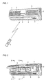
- FIG. 1 is a schematic front perspective of the indoor unit of the air conditioner in accordance with the present embodiment
- Fig. 2 is a front perspective with the front panel of Fig. 1 opened. As can be seen from Fig.
- indoor unit 1 includes a body casing 2 in which a heat exchanger and an indoor fan are in provided, a front panel 3 which can be opened for visually inspecting the inside of the body to check dirt on the filter, an outlet 4 letting out cooled/heated air, an inlet 5 sucking in indoor air, a main liquid crystal display apparatus 6 displaying a state of operation, and an outlet 7 letting out air from a humidifying/dehumidifying apparatus.
- a remote controller 8 is for remote-controlling power on/off or for changing the state of operation.
- a right filter 9 and a left filter 10 are arranged at a lattice-like inlet of body casing 2 facing inlet 5 of front panel (see Fig. 1), and air cleaning filters 11 and 12 are mounted approximately at the central portions of right filter 9 and left filter 10, respectively.
- a filter 13 for an inlet for the humidifying/dehumidifying apparatus to suck in the indoor air is provided at a left end portion of the body casing 2.
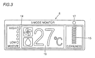
- a main liquid crystal display apparatus 6 is provided at the central portion of indoor unit 1.
- Main liquid crystal display apparatus 6 includes a moisture lamp 14 which is turned on in accordance with the moisture in the room, a purity lamp 15 of which color changes in accordance with the degree of contamination of the room, a display unit 16 displaying indoor environment and the state of operation in accordance with a signal from an operation button of a remote controller 8, and a light receiving portion 17 receiving a signal from remote controller 8.
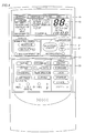
- Remote controller 8 shown in Fig. 4 includes a remote controller display unit 18 displaying the state of operation, a transmission display 19 which is turned on when a signal is transmitted to indoor unit 1, an operation on/off switch 20 for turning on/off the operation of the air conditioner, a temperature switch 21 for setting the indoor temperature, an operation selecting switch 22 for selecting an operation mode, and flow rate switch 23 for switching the flow rate.
- Fig. 5 is a cross sectional view taken along the line A-A of Fig. 2 of the body of indoor unit 1.
- Indoor unit 1 includes a body casing 2 as a base of indoor unit 1, an indoor heat exchanger 25 through which a heating/cooling medium (refrigerant) is passed for heat-exchanging between the indoor and outdoor air, an indoor fan 26 sucking in the indoor air and blowing out the air heat-exchanged by the indoor heat exchanger 25, a vertical louver 27 for changing air flow in the left and right directions at the outlet 4 of body casing 2, and a horizontal louver 28 for changing the air flow in the upward and downward directions. Further, air cleaning filters 11 and 12 for removing dust in the air sucked in through the inlet are provided on the left and right portions.
- a heating/cooling medium refrigerant
- air cleaning filters 11 and 12 are inserted through filter guides 29 of body casing 2.
- Right filter 11 has such a shape that is branched at the portion of the liquid crystal display apparatus in order to remove dust in the air from the room also in the space behind the main liquid crystal apparatus 6.
- a drain pan 30 is arranged below indoor heat exchanger 25 to receive drainage generated when heat-exchange with the indoor air takes place.
- an inlet 31 for sucking in the indoor air is formed, and an inlet 32 for sucking in the indoor air is also provided at an upper surface of body casing 2.
- Fig. 6 is a cross sectional view taken along the line B-B of Fig. 2 of indoor unit 1. Different from the cross section of Fig. 5 taken along the line A-A, there is not the main liquid crystal display apparatus 6, and therefore, the shape of the front panel 3 is relatively flat, as it does not have the projected portion covering the main liquid crystal display apparatus 6, and an inlet 5 is formed at the front surface.
- Main liquid crystal display apparatus 6 includes a liquid crystal display 33 displaying the indoor environment and the state of operation in accordance with a signal from an operation button of the remote controller, a display substrate 35 on which an LED 34 for illuminating the liquid crystal display 33 is mounted, and a liquid crystal holder 36 holding the liquid crystal display 33, as shown in Fig. 7.
- Liquid crystal holder 36 includes a portion receiving liquid crystal display 33 and a portion for fixing on the body casing 2, and there are a plurality of partition walls 37, on the right side of which a fixing portion 38 for fixing on the body casing 2 is formed.
- Main liquid crystal display apparatus 6 is mounted on body casing 2 in the manner as shown in Fig. 8. More specifically, main liquid crystal display apparatus 6 is mounted on body casing 2 by fixing the fixing portion 38 of partition wall 37 of the liquid crystal holder 36 by means of a screw.
- Operation mode of the air conditioner is switched every time the "operation selection" switch 22 on the control panel of remote controller 8 is pressed, in the order of "automatic” - “heating” - “cooling” - “dry” - “automatic”-, the operation mode is displayed on display unit 18 of remote controller 8, and the user selects the operation mode accordingly.
- the amount of temperature to be increased is displayed on remote controller display unit 18 on the control panel of remote controller 8, while the set temperature is displayed on the main liquid crystal display apparatus 6 of indoor unit 1. At this time, the display of the set temperature on the main liquid crystal display apparatus 6 of indoor unit 1 returns to the display of the room temperature after approximately 4 seconds.
- "flow rate" switch 23 on the control panel of remote controller 8 is pressed.
- a heat exchange medium at a high temperature condensed by a compressor is fed to an outdoor heat exchanger of an outdoor unit.
- outdoor air deprives the heat exchange medium of heat as it passes through the outdoor heat exchanger by the operation of an outdoor fan, and the heat exchange medium is cooled.
- the heat exchange medium passes through a decompressor, evaporated at an indoor heat exchanger 25 of indoor unit 1, and deprives the air in the room of heat as the air in the room is passed by the indoor fan 26 through the indoor heat exchanger 25. In this manner, the air in the room is cooled, and the room is cold.
- Heating of the room is performed by reverse-circulating the heat exchange medium in the direction reverse to the cooling operation.
- Condensed heat exchange medium is fed to the indoor heat exchanger 25 of indoor unit 1, so as to warm up the air in the room passing through indoor heat exchanger 25.
- the heat exchange medium is further passed through the decompresser, evaporated at the outdoor heat exchanger of the outdoor unit, and after the outdoor air is passed through the outdoor heat exchanger by the outdoor fan and heat-exchange takes place, deprives the outdoor air of heat, and returns to the compressor.
- the indoor air is sucked in through the inlet 12 positioned above the humidifying/dehumidifying apparatus and inlet 5 of the front panel 3 of indoor unit 1, passes through the left filter 10 and enters to the indoor heat exchanger 25, on one hand, and the indoor air entering through inlet 31 above main liquid crystal display apparatus 6 passes through right filter 9, enters to the space between main liquid crystal display apparatus 6 and indoor heat exchanger 25 and enters the indoor heat exchanger 25 through a passage between partition walls 37 of liquid crystal holder 36 on the other hand. Namely, the indoor air is sucked in, fully utilizing the surface of indoor heat exchanger 25. Therefore, heat exchange effectiveness at the indoor heat exchanger 25 is improved, and COP is also improved.
- the humidifying/dehumidifying apparatus (not shown) arranged on the right side of the body 2 of indoor unit 1 sucks in the indoor air to be humidified/dehumidified through inlet 13 of body 2 through a filter 13.
- the humidifying/dehumidifying apparatus absorbs moisture in the indoor air and discharges the dry air to the outside of the room, and discharges moist air to the room.
- the apparatus is also capable of a dehumidifying operation in which moist air is discharged to the outside of the room and the dry air is discharged to the room.
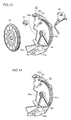
- Fig. 9 is a perspective view showing an appearance of the indoor unit of an air conditioner.
- Fig. 10 is a perspective view showing a humidifying/dehumidifying apparatus not belonging to the subject-matter of the present invention, this apparatus being attached to the indoor unit, and
- Fig. 11 shows a configuration of the humidifying/dehumidifying apparatus of Fig. 10.
- the humidifying/dehumidifying apparatus is attached to a right end portion when viewed from the front side, of the indoor unit 1.
- An inlet 5 sucking in the indoor air is provided at a front panel 3 of indoor unit 1.
- a body casing 2 is formed.
- an inlet 5a for sucking in the indoor air of humidifying/dehumidifying apparatus 24 is arranged.
- an exhaust outlet 43 for discharging air from the humidifying/dehumidifying apparatus 24 to the outside of the room is provided, to which an exhaust duct 12 is connected.
- a moisture absorbing rotor 39 is an absorber including a number of cylindrical ceramic members, on which a substance absorbing water in the air is applied.
- Moisture absorbing rotor 39 is driven to rotate at a low speed by a motor 49 with a speed change gear 50 inserted therebetween.
- a moisture absorbing fan 51 is driven by a moisture absorbing fan motor, which sucks in the indoor air, passes the air to the moisture absorbing rotor 39, and thereafter guides the air to the exhaust duct 52 to be exhausted to the outside of the room.
- a recovery fan 41 is driven by a recovery fan motor, and it serves to pass the air sucked in from the room through moisture absorbing rotor 39, to guide the air to the recovery heater 42 so that the air is again passed through moisture absorbing rotor 39, and to return the resulting air to the room through the outlet 7.
- some of the water in the air is absorbed by moisture absorbing rotor 39, as the indoor air passes through moisture absorbing rotor 39.
- the water which has been absorbed by moisture absorbing rotor 39 is desorbed by the heat of recovery heater 42, and much moisture of the air passed therethrough is absorbed.
- the air in the room is dehumidified.
- a humidifying operation the dried air is discharged to the outside, and moist air is fed to the inside of the room, so that the moisture contained in the indoor air is accumulated, the moisture in the room is increased, and the room is humidified.
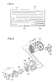
- Moisture absorbing rotor 39 having a moisture absorbing substance applied thereon is provided at the center of humidifying/dehumidifying apparatus 24, and zeolite powder with an adhesive mixed is used as the moisture absorbing substance.
- a moisture absorbing fan 51 of a sirocco fan and a moisture absorbing motor are arranged on an upper right side of moisture absorbing rotor 39, and recovery heater 42 is arranged at a lower portion. Behind moisture absorbing fan 51, exhaustion duct 52 is connected. Exhaustion duct 52 has such a structure that accommodates various extension ducts having different lengths and shapes, in accordance with positional correlation of connecting pipe holes of the indoor and outdoor units, when the air conditioner is installed.
- recovery fan 41 that is the sirocco fan, and the recovery fan motor are provided.
- a synchronous motor 49 for rotating moisture absorbing rotor 39, and a reduction gear 50 for reducing the speed of rotation of moisture absorbing rotor 39 are provided.
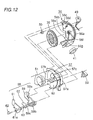
- Humidifying/dehumidifying apparatus 24 is formed by a combination of a plurality of resin cases as shown in Fig. 12, and an inlet 56a, which has a number of aligned rectangular holes for sucking in the indoor air, is provided at a case R56. At a position opposite to inlet 56a, there is a cut-out 56b. Near the cut-out 56b, there is a mounting portion 56c in which motor 49 is placed. Mounting portion 56c has a gear receiving portion 56d receiving the reduction gear 50 for rotating moisture absorbing rotor 39 at a reduced speed, and the receiving portion 56d has a through hole. Cut-out 56b may have a structure that is sealed by a detachable cover.
- case R56 At the central portion of case R56, there is a bearing portion for the rotation shaft of moisture absorbing rotor 39. At a tip end portion of case R56, there is a wall 56e in the form of an involute curve, for mounting the recovery fan 41, and a casing formed of a boss for fixing the motor continuous to the wall 56e. There is a chamber 56f through which the recovered air is passed, and a passage passing through the chamber 56f to enter recovery fan 41. There is a receiving portion of a concave shape, accommodating motor 49, outside the case R56, and near this portion, there are two bosses on each of the left and right portions, that is, a positioning boss for fixing motor 49 and a boss with a hole provided at the center.
- a case L57 has a bearing boss for the moisture absorbing rotor 39 at the central portion of a surface opposing to case R56, and a wall 57a at a small distance away from the outer periphery of moisture absorbing rotor 39, and holes are provided in approximately one half (about 180°) the bottom surface, so as to pass the recovered air therethrough.
- holes 57c At the side opposing to the holes, there are holes 57c of about 60 mm, for passing the air that has passed through the moisture absorbing rotor 39.
- At a surface opposing to the mounting surface of moisture absorbing rotor 39 there is a wall 57b of the casing for moisture absorbing fan 51, sucking in the indoor air through moisture absorbing rotor 39.
- On the downstream side of the passage there is a passage to a damper unit 58 for switching passages, and there is a plurality of holes for mounting a metal cover in which recovery heater 42 for heating the recovering air is placed.
- case L57 On the left side of case L57, there is the damper unit 58 which is formed by combining two transparent resin cases, in which a damper 60 is contained.
- a damper 60 On the case L59 of damper unit 58 on the side of case L57, an inlet 59a for the dried air from moisture absorbing fan 51, an inlet 59b of moist air with moisture desorbed by moisture absorbing rotor 39, and a duct connecting hole 59c for discharging to the outside of the room, are provided.
- a bearing boss for damper 60 at the central portion, and in the vicinity thereof, there is a receiving portion for the reduction gear 63 from a damper driving motor 62.
- damper unit 58 there is an indoor outlet 61a for feeding the air back into the room, and in the vicinity thereof, there is a hole for mounting a motor for driving damper 60.
- damper 60 there is a bearing boss at the central portion, gears are arranged at approximately 1/4 of the outer periphery, and there is a wall for switching air passage.
- the procedure for assembling humidifying/dehumidifying apparatus 24 is as follows.
- the motor mounting plate on which recovery fan 41 and the motor are fixed is mounted on a prescribed portion of case L56 by means of a screw, and moisture absorbing rotor 39 is fitted to the shaft of case L56, with the outer peripheral gear side facing the side of case L56. Further, reduction gear 50 is also mounted on a prescribed position.
- Case R5 7 with the metal cover 60 incorporating recovery heater 42 therein at a prescribed position is combined and fixed to case L56 by means of a screw. At this time, moisture absorbing rotor 39 is manually rotated through the cut-out 56b of case L56, whereby manual inspection by touching is possible, to check any deviation or contact at the time of rotation.
- damper unit 58 having damper 60 and damper motor 62 mounted thereon is mounted on case L56, whereby humidifying/dehumidifying apparatus 24 is finished.
- the function and the structure of the humidifying/dehumidifying apparatus as well as the air flow will be described, with reference to a humidifying operation.
- the air sucked in from the room is sucked through inlet 5 on the front surface of front panel 3 and inlet at an upper portion of body casing 2, and the air is guided to a left side surface of moisture absorbing rotor 39 through filter 13.
- On both sides of moisture absorbing rotor 39 air flow paths are formed respectively at the angles as shown in Fig. 16, and a rubber packing having such a shape that slides over the rotor surface is provided for sealing, so as to prevent leakage of air at a portion that is in contact with the rotor.
- the air sucked in by moisture absorbing rotor 51 passes through the area A having the area of 1/2 (180°) of the rotor side surface shown in Fig. 16 and, at this time, the water in the air is absorbed by the moisture absorbing substance applied on the rotor, so that after the passage through moisture absorbing rotor 39, the air is dry.
- the dried air is passed through exhaustion duct 52 and discharged to the outside of the room, by the function of the sirocco fan, operated by the motor of moisture absorbing fan 51.
- the air sucked in by the motor of recovery fan 41 passes through the areas B and D of Fig.
- the moisture absorbing function of area D is small, as the area D follows the area C of moisture absorbing rotor 39 and the temperature of the ceramics as the material of the moisture absorbing rotor 39 is not yet sufficiently low.
- the air which has passed through areas B and D is heated to a high temperature as it passes through recovery heater 42, and thereafter, the air passes from the right side surface of moisture absorbing rotor 39 through an area of 1/4 (90°) of the side surface of moisture absorbing rotor 39 of area C shown in Fig. 5, to the left side surface.
- the water absorbed in the moisture absorbing substance on moisture absorbing rotor 39 is heated, and emitted from the moisture absorbing substance.
- the air containing much moisture enters from the right side surface of moisture absorbing rotor 39 to the recovery fan 42, and blown out to the inside of the room through outlet 7.
- the dried air is discharged to the outside of the room, and the moist is accumulated in the room, so that room is humidified.
- the humidifying/dehumidifying apparatus 24 assembled in this manner allows manual inspection by touching the moisture absorbing rotor 39 through the cut-out 56b of case R56 in the process of assembly. Therefore, any problem can be found at an earlier stage, and if there should be a trouble, the time necessary for disassembly can significantly be reduced.
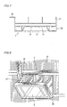
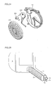
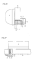
- auxiliary duct 78 such as shown in Figs. 17 and 18 is coupled to an outdoor side end of ventilation duct 75.
- Auxiliary duct 78 is molded by a hard resin, for example, and has a coupling portion 79 to be coupled to ventilation duct 75, and an outlet side end 80 having an approximately semicircular shape. As is apparent from Fig. 20, outlet side end 80 is molded, twisted by about 90° from the coupling portion 79.
- coupling portion 79 has an approximately semicircular shape as the cross sectional shape of ventilation duct 75 is approximately semicircular, the shape is not limited to semicircular, and the shape may be adapted in accordance with the cross sectional shape of ventilation duct 75.
- a weather cover 81 for avoiding rain is mounted on an outdoor surface of wall 76, and various pipes, ventilation duct 75 and auxiliary duct 78 are guided to weather cover 81.
- the air discharged from indoor unit A through ventilation duct 75 and auxiliary duct 78 are exhausted to the outside of the room through an outlet 82 of weather cover 81.
- the coupling portion 79 of auxiliary duct 78 is adapted to be a coupling portion 79 of different diameters, having stepwise large diameter portion 79a and a small diameter portion 79b, so as to cope with a case where the pipe hole 77 is small and a ventilation duct 5 of small diameter must be used. Therefore, when the ventilation duct 75 to be coupled has a small diameter, it is possible to couple the auxiliary duct directly to the ventilation duct 75 by simply cutting the large diameter portion 79a.
- the outlet side end opening 83 of auxiliary duct 78 is cut obliquely, and therefore, when the duct is guided to weather cover 81 and brought into contact with the wall surface of weather cover 81, circulation of the air is not hindered, and good state of ventilation is ensured.
- the outlet side end opening 83 is cut obliquely upward in the shown example, the direction is not limited as long as the opening is cut obliquely.
- an auxiliary duct having an approximately semicircular outlet side end twisted by about 90° with respect to a coupling portion of the ventilating duct is coupled to an outdoor side end of the ventilation duct. Therefore, even when it is necessary to bend various pipes to cross the longitudinal axis of the ventilation duct, it becomes possible to bend the pipes not passing between an outlet end surface of the ventilation duct and the weather cover. Therefore, decrease in circulation efficiency of the air passing through the ventilation duct can be prevented.
- the coupling portion for coupling the auxiliary duct to the ventilation duct is adapted to be a coupling portion having cross sections of different diameters, it is unnecessary to prepare a separate auxiliary duct even when a pipe hole through which the ventilation duct is passed is small and a ventilation duct of a small size is necessary.
Landscapes
- Engineering & Computer Science (AREA)
- Chemical & Material Sciences (AREA)
- Combustion & Propulsion (AREA)
- Mechanical Engineering (AREA)
- General Engineering & Computer Science (AREA)
- Human Computer Interaction (AREA)
- Physics & Mathematics (AREA)
- Thermal Sciences (AREA)
- Air Humidification (AREA)
- Drying Of Gases (AREA)
- Central Air Conditioning (AREA)
- Duct Arrangements (AREA)
Applications Claiming Priority (7)
| Application Number | Priority Date | Filing Date | Title |
|---|---|---|---|
| JP29195699 | 1999-10-14 | ||
| JP29195699A JP3619406B2 (ja) | 1999-10-14 | 1999-10-14 | 空気調和機 |
| JP29319499A JP3638834B2 (ja) | 1999-10-15 | 1999-10-15 | 除加湿装置 |
| JP29319499 | 1999-10-15 | ||
| JP35276099A JP3327888B2 (ja) | 1999-12-13 | 1999-12-13 | 空気調和機 |
| JP35276099 | 1999-12-13 | ||
| EP00122158A EP1092927B1 (fr) | 1999-10-14 | 2000-10-12 | Installation de climatisation avec dispositif d'humidification/déshumidification |
Related Parent Applications (1)
| Application Number | Title | Priority Date | Filing Date |
|---|---|---|---|
| EP00122158.9 Division | 2000-10-12 |
Publications (2)
| Publication Number | Publication Date |
|---|---|
| EP1526343A2 true EP1526343A2 (fr) | 2005-04-27 |
| EP1526343A3 EP1526343A3 (fr) | 2005-11-23 |
Family
ID=27337703
Family Applications (3)
| Application Number | Title | Priority Date | Filing Date |
|---|---|---|---|
| EP05001543A Withdrawn EP1526343A3 (fr) | 1999-10-14 | 2000-10-12 | Installation de climatisation avec dispositif d'humidification/déshumidification |
| EP05001542A Withdrawn EP1526342A3 (fr) | 1999-10-14 | 2000-10-12 | Installation de climatisation avec dispositif d'humidification/déshumidification |
| EP00122158A Expired - Lifetime EP1092927B1 (fr) | 1999-10-14 | 2000-10-12 | Installation de climatisation avec dispositif d'humidification/déshumidification |
Family Applications After (2)
| Application Number | Title | Priority Date | Filing Date |
|---|---|---|---|
| EP05001542A Withdrawn EP1526342A3 (fr) | 1999-10-14 | 2000-10-12 | Installation de climatisation avec dispositif d'humidification/déshumidification |
| EP00122158A Expired - Lifetime EP1092927B1 (fr) | 1999-10-14 | 2000-10-12 | Installation de climatisation avec dispositif d'humidification/déshumidification |
Country Status (4)
| Country | Link |
|---|---|
| EP (3) | EP1526343A3 (fr) |
| CN (3) | CN1246647C (fr) |
| AU (1) | AU776223B2 (fr) |
| ES (1) | ES2267442T3 (fr) |
Families Citing this family (27)
| Publication number | Priority date | Publication date | Assignee | Title |
|---|---|---|---|---|
| KR100671109B1 (ko) | 2003-03-26 | 2007-01-17 | 다이킨 고교 가부시키가이샤 | 공기 조화기의 실내기 |
| KR100626443B1 (ko) * | 2003-11-24 | 2006-09-20 | 엘지전자 주식회사 | 공기조화기의 실내기 |
| WO2005103574A1 (fr) * | 2004-04-20 | 2005-11-03 | Lg Electronics Inc. | Climatiseur |
| CN100455917C (zh) * | 2004-06-21 | 2009-01-28 | 乐金电子(天津)电器有限公司 | 空调器 |
| EP1888973B1 (fr) * | 2005-05-11 | 2016-09-07 | LG Electronics Inc. | Conditionneur d'air |
| CN1959235B (zh) * | 2005-11-01 | 2011-01-26 | 乐金电子(天津)电器有限公司 | 空调设备的显示屏安装用组装体 |
| WO2008007841A2 (fr) * | 2006-07-13 | 2008-01-17 | Lg Electronics Inc. | Conditionneur d'air à fonction d'affichage d'image |
| KR20080006757A (ko) * | 2006-07-13 | 2008-01-17 | 엘지전자 주식회사 | 평판표시유닛이 설치된 공기조화기 |
| CN101178217B (zh) * | 2006-11-08 | 2011-11-30 | 乐金电子(天津)电器有限公司 | 除湿机 |
| KR101318358B1 (ko) * | 2006-12-18 | 2013-10-15 | 엘지전자 주식회사 | 공기조화기 |
| EP2045541B1 (fr) * | 2007-10-02 | 2015-09-02 | LG Electronics Inc. | Dispositif de contrôle pour climatiseur |
| EP2274062A2 (fr) * | 2008-03-06 | 2011-01-19 | Megair Ltd. | Procédé et appareil permettant de traiter l'air |
| KR20100025332A (ko) * | 2008-08-27 | 2010-03-09 | 엘지전자 주식회사 | 제습기 |
| CN101825315A (zh) * | 2010-05-05 | 2010-09-08 | 广东美的电器股份有限公司 | 一种空调器室内机 |
| CN102062447A (zh) * | 2010-12-31 | 2011-05-18 | 广东美的电器股份有限公司 | 一种分体壁挂式空调器室内机 |
| JP5310904B1 (ja) * | 2012-04-16 | 2013-10-09 | ダイキン工業株式会社 | 空気調和機 |
| CN104121683A (zh) * | 2013-04-27 | 2014-10-29 | 珠海格力电器股份有限公司 | 面板部件、空调器及空调器的制造方法 |
| JP6563287B2 (ja) * | 2015-09-18 | 2019-08-21 | シャープ株式会社 | 除加湿装置 |
| US11125479B1 (en) * | 2016-09-28 | 2021-09-21 | Joi Holding Llc | Apparatus and process for amateur HVAC installation |
| CN108266867B (zh) * | 2018-01-11 | 2020-02-04 | 广东美的制冷设备有限公司 | 空调器的控制方法和空调器 |
| CN109915944B (zh) * | 2019-04-10 | 2024-05-03 | 珠海格力电器股份有限公司 | 一种空调器 |
| CN110953706B (zh) * | 2019-12-25 | 2021-08-13 | 广东美博制冷设备有限公司 | 一种空调机壳体结构和空调机 |
| CN113375240B (zh) * | 2020-12-31 | 2022-08-12 | 重庆绿安信息科技有限公司 | 一种智能一体化库房管理系统 |
| CN113483389B (zh) * | 2021-06-22 | 2023-03-21 | 青岛海尔空调器有限总公司 | 空调室内机和空调器 |
| CN114323475B (zh) * | 2021-11-18 | 2023-11-07 | 国网河北省电力有限公司电力科学研究院 | 空冷机组真空检漏除湿装置 |
| CN114484846B (zh) * | 2022-02-23 | 2024-04-23 | 武汉海尔电器股份有限公司 | 壁挂式空调器及其凝露处理方法 |
| CN115377811B (zh) * | 2022-07-25 | 2024-07-09 | 国网安徽省电力有限公司岳西县供电公司 | 一种电网系统中野外电力柜的除湿装置 |
Citations (4)
| Publication number | Priority date | Publication date | Assignee | Title |
|---|---|---|---|---|
| JPH0473531A (ja) * | 1990-07-10 | 1992-03-09 | Mitsubishi Electric Corp | 換気機能付き空気調和機 |
| JPH0571753A (ja) * | 1991-09-17 | 1993-03-23 | Fujitsu General Ltd | 空気調和機の換気装置 |
| JPH1019303A (ja) * | 1996-07-04 | 1998-01-23 | Daikin Ind Ltd | セパレート型空気調和機の換気ダクト構造 |
| EP0823596A2 (fr) * | 1996-07-30 | 1998-02-11 | SHARP Corporation | Dispositif de climatisation avec humidification |
Family Cites Families (5)
| Publication number | Priority date | Publication date | Assignee | Title |
|---|---|---|---|---|
| US2266219A (en) * | 1941-12-16 | a larriva | ||
| JP3242762B2 (ja) * | 1993-08-30 | 2001-12-25 | 株式会社日立製作所 | 空気調和機 |
| JP3269007B2 (ja) * | 1997-05-30 | 2002-03-25 | 三洋電機株式会社 | 空気調和機 |
| JPH11159846A (ja) | 1997-11-28 | 1999-06-15 | Matsushita Electric Ind Co Ltd | 空気調和機の表示装置 |
| JPH11248204A (ja) * | 1998-02-26 | 1999-09-14 | Sanyo Electric Co Ltd | 空気調和機 |
-
2000
- 2000-10-12 ES ES00122158T patent/ES2267442T3/es not_active Expired - Lifetime
- 2000-10-12 EP EP05001543A patent/EP1526343A3/fr not_active Withdrawn
- 2000-10-12 EP EP05001542A patent/EP1526342A3/fr not_active Withdrawn
- 2000-10-12 EP EP00122158A patent/EP1092927B1/fr not_active Expired - Lifetime
- 2000-10-13 CN CNB2003101232991A patent/CN1246647C/zh not_active Expired - Fee Related
- 2000-10-13 AU AU66519/00A patent/AU776223B2/en not_active Ceased
- 2000-10-13 CN CNB001304968A patent/CN1165714C/zh not_active Expired - Fee Related
- 2000-10-13 CN CNB2003101232987A patent/CN1244779C/zh not_active Expired - Fee Related
Patent Citations (4)
| Publication number | Priority date | Publication date | Assignee | Title |
|---|---|---|---|---|
| JPH0473531A (ja) * | 1990-07-10 | 1992-03-09 | Mitsubishi Electric Corp | 換気機能付き空気調和機 |
| JPH0571753A (ja) * | 1991-09-17 | 1993-03-23 | Fujitsu General Ltd | 空気調和機の換気装置 |
| JPH1019303A (ja) * | 1996-07-04 | 1998-01-23 | Daikin Ind Ltd | セパレート型空気調和機の換気ダクト構造 |
| EP0823596A2 (fr) * | 1996-07-30 | 1998-02-11 | SHARP Corporation | Dispositif de climatisation avec humidification |
Non-Patent Citations (3)
| Title |
|---|
| PATENT ABSTRACTS OF JAPAN vol. 016, no. 284 (M-1270), 24 June 1992 (1992-06-24) -& JP 04 073531 A (MITSUBISHI ELECTRIC CORP), 9 March 1992 (1992-03-09) * |
| PATENT ABSTRACTS OF JAPAN vol. 017, no. 395 (M-1451), 23 July 1993 (1993-07-23) -& JP 05 071753 A (FUJITSU GENERAL LTD), 23 March 1993 (1993-03-23) * |
| PATENT ABSTRACTS OF JAPAN vol. 1998, no. 05, 30 April 1998 (1998-04-30) -& JP 10 019303 A (DAIKIN IND LTD), 23 January 1998 (1998-01-23) * |
Also Published As
| Publication number | Publication date |
|---|---|
| CN1244779C (zh) | 2006-03-08 |
| CN1246647C (zh) | 2006-03-22 |
| EP1526342A3 (fr) | 2005-11-23 |
| EP1092927A3 (fr) | 2002-07-31 |
| EP1092927B1 (fr) | 2006-07-26 |
| CN1504696A (zh) | 2004-06-16 |
| EP1526343A3 (fr) | 2005-11-23 |
| CN1293340A (zh) | 2001-05-02 |
| AU776223B2 (en) | 2004-09-02 |
| ES2267442T3 (es) | 2007-03-16 |
| EP1526342A2 (fr) | 2005-04-27 |
| EP1092927A2 (fr) | 2001-04-18 |
| CN1165714C (zh) | 2004-09-08 |
| AU6651900A (en) | 2001-04-26 |
| CN1504695A (zh) | 2004-06-16 |
Similar Documents
| Publication | Publication Date | Title |
|---|---|---|
| EP1092927B1 (fr) | Installation de climatisation avec dispositif d'humidification/déshumidification | |
| EP1785678A2 (fr) | Conditionneur d'air | |
| JP2008122047A (ja) | 空気調和機 | |
| JP2004092950A (ja) | 空気調和機の室内機 | |
| EP1318356B1 (fr) | Climatiseur | |
| KR20020086260A (ko) | 공기 조화기 | |
| JP2006234289A (ja) | 一体型空気調和機 | |
| JP3564525B2 (ja) | 空気調和機 | |
| JP4429123B2 (ja) | 空気調和機 | |
| JP2006078159A (ja) | 空気調和機 | |
| JP3619406B2 (ja) | 空気調和機 | |
| WO2019194097A1 (fr) | Climatiseur | |
| JP4226012B2 (ja) | 空気調和機 | |
| JP2006078160A (ja) | 空気調和機 | |
| KR200274979Y1 (ko) | 창문일체형 고정식 열교환 환기장치 | |
| JP4592368B2 (ja) | 空気調和機 | |
| JP2005009716A (ja) | 給排気装置及び該給排気装置を備えた空気調和機。 | |
| KR100311860B1 (ko) | 공기조화기 | |
| JP2002071174A (ja) | 加湿ユニット | |
| KR200170250Y1 (ko) | 집중 냉방식 원통형 에어컨 | |
| JPH05203188A (ja) | 空気調和機 | |
| KR100289488B1 (ko) | 에어컨의흡입그릴개폐장치 | |
| JPH05203181A (ja) | 空気調和機 | |
| JP2008122020A (ja) | 空気調和機の室内機 | |
| JP2007101058A (ja) | 加湿ユニット |
Legal Events
| Date | Code | Title | Description |
|---|---|---|---|
| PUAI | Public reference made under article 153(3) epc to a published international application that has entered the european phase |
Free format text: ORIGINAL CODE: 0009012 |
|
| AC | Divisional application: reference to earlier application |
Ref document number: 1092927 Country of ref document: EP Kind code of ref document: P |
|
| AK | Designated contracting states |
Kind code of ref document: A2 Designated state(s): ES FR IT |
|
| RIN1 | Information on inventor provided before grant (corrected) |
Inventor name: MORIKAWA, MAMORU Inventor name: SUZUKI, MASAKAZU Inventor name: SHIBORINO, YOSHINOBU Inventor name: OKA, TAKANORI Inventor name: IIDA, HIROYUKI |
|
| PUAL | Search report despatched |
Free format text: ORIGINAL CODE: 0009013 |
|
| AK | Designated contracting states |
Kind code of ref document: A3 Designated state(s): ES FR IT |
|
| RIC1 | Information provided on ipc code assigned before grant |
Ipc: 7F 24F 1/00 A |
|
| 17P | Request for examination filed |
Effective date: 20060224 |
|
| AKX | Designation fees paid |
Designated state(s): IT |
|
| STAA | Information on the status of an ep patent application or granted ep patent |
Free format text: STATUS: THE APPLICATION HAS BEEN WITHDRAWN |
|
| 18W | Application withdrawn |
Effective date: 20120320 |