EP1526300B1 - Kraftübertragungsmechanismus - Google Patents
Kraftübertragungsmechanismus Download PDFInfo
- Publication number
- EP1526300B1 EP1526300B1 EP04255588A EP04255588A EP1526300B1 EP 1526300 B1 EP1526300 B1 EP 1526300B1 EP 04255588 A EP04255588 A EP 04255588A EP 04255588 A EP04255588 A EP 04255588A EP 1526300 B1 EP1526300 B1 EP 1526300B1
- Authority
- EP
- European Patent Office
- Prior art keywords
- drive shaft
- clutch
- collar
- projecting
- housing
- Prior art date
- Legal status (The legal status is an assumption and is not a legal conclusion. Google has not performed a legal analysis and makes no representation as to the accuracy of the status listed.)
- Expired - Lifetime
Links
- 230000007246 mechanism Effects 0.000 title claims description 28
- 230000005540 biological transmission Effects 0.000 title claims description 26
- 230000002093 peripheral effect Effects 0.000 claims description 10
- 238000007789 sealing Methods 0.000 claims description 10
- 239000000463 material Substances 0.000 description 5
- 238000010586 diagram Methods 0.000 description 4
- 229910000831 Steel Inorganic materials 0.000 description 3
- 239000010959 steel Substances 0.000 description 3
- 230000015572 biosynthetic process Effects 0.000 description 2
- WYTGDNHDOZPMIW-RCBQFDQVSA-N alstonine Natural products C1=CC2=C3C=CC=CC3=NC2=C2N1C[C@H]1[C@H](C)OC=C(C(=O)OC)[C@H]1C2 WYTGDNHDOZPMIW-RCBQFDQVSA-N 0.000 description 1
- 239000000969 carrier Substances 0.000 description 1
- 238000004880 explosion Methods 0.000 description 1
- 230000002452 interceptive effect Effects 0.000 description 1
- 238000004519 manufacturing process Methods 0.000 description 1
- 239000011435 rock Substances 0.000 description 1
- 102220033831 rs145989498 Human genes 0.000 description 1
- 238000004381 surface treatment Methods 0.000 description 1
Images





Classifications
-
- F—MECHANICAL ENGINEERING; LIGHTING; HEATING; WEAPONS; BLASTING
- F16—ENGINEERING ELEMENTS AND UNITS; GENERAL MEASURES FOR PRODUCING AND MAINTAINING EFFECTIVE FUNCTIONING OF MACHINES OR INSTALLATIONS; THERMAL INSULATION IN GENERAL
- F16D—COUPLINGS FOR TRANSMITTING ROTATION; CLUTCHES; BRAKES
- F16D41/00—Freewheels or freewheel clutches
- F16D41/12—Freewheels or freewheel clutches with hinged pawl co-operating with teeth, cogs, or the like
- F16D41/16—Freewheels or freewheel clutches with hinged pawl co-operating with teeth, cogs, or the like the action being reversible
-
- F—MECHANICAL ENGINEERING; LIGHTING; HEATING; WEAPONS; BLASTING
- F16—ENGINEERING ELEMENTS AND UNITS; GENERAL MEASURES FOR PRODUCING AND MAINTAINING EFFECTIVE FUNCTIONING OF MACHINES OR INSTALLATIONS; THERMAL INSULATION IN GENERAL
- F16D—COUPLINGS FOR TRANSMITTING ROTATION; CLUTCHES; BRAKES
- F16D41/00—Freewheels or freewheel clutches
- F16D41/12—Freewheels or freewheel clutches with hinged pawl co-operating with teeth, cogs, or the like
Definitions
- the present invention relates to power transmission mechanisms employing a one-way clutch in a drivetrain.
- One-way clutches which transmit power in a fixed direction, are, for example, provided at right and left ends of a drive shaft of a self-propelled walk-behind lawn mower in order to facilitate turning of the lawn mower and allow the lawn mower, when moved with an engine stopped, to be easily pushed and moved by hand (see, e.g., U.S. Patent No. 4909365 and Japanese Patent Laid-Open Publication No. 2001-59531 ).
- a clutch mechanism 100 is used for transmitting a driving force of a drive shaft 101 to a pinion 102.
- the clutch mechanism 100 includes, as its main elements, a key 103 and a friction disc 104.
- the key 103 has a wedge portion 103a to be received in a first keyway 105 axially formed in the drive shaft 101, in such a manner as to be able to rock therein to extend therefrom and retract thereinto, and a projecting portion 103b to be received in a hollowed portion 104a formed in the friction disc 104.
- the wedge portion 103a has a thick side portion forming an engaging portion 103c.
- the key 103 When the drive shaft 101 is rotated, the key 103 is simultaneously rotated, causing the projecting portion 103b of the key 103 to abut on the hollowed portion 104a of the friction disc 104. Since the friction disc 104 is in frictional engagement with a housing 106, the projecting portion 103b of the key 103 is not moved further. Thus, the wedge portion 103a of the key 103 is cocked, projecting from within the first keyway 105. The engaging portion 103c of the wedge portion 103a engages one of a plurality of second keyways 102a formed in the inner peripheral surface of the pinion 102, thereby ensuring transmission of a driving force of the drive shaft 101 to the pinion 102.
- the wedge portion 103a of the key 103 is received within the first keyway 105 without being cocked, and the pinion 102 can rotate bidirectionally relative to the drive shaft 101.
- the above clutch mechanism 100 has a problem that, for producing rotation resistance at the friction disc 104 by a thrust spring 107, it is necessary to reduce variations in friction coefficient between the surface of the housing 106, the opposite surfaces of the friction disc 104 and the surface of the pinion 102, resulting in time-consuming surface treatment of these components.
- a power transmission mechanism 200 shown in FIG. 10A includes a drive shaft 201, a plurality of pins 203 (three in the illustrated example) fitted in a plurality of cam grooves 202 formed in the drive shaft 201, a gear 204 and a friction disc 205 fitted onto the drive shaft 201, and an oil seal 206 fitted onto the friction disc 205.
- the pins 203 are detached from the inner peripheral surface of the gear 204 forming a hole 207, allowing the gear 204 to rotate bidirectionally relative to the drive shaft 201.
- the above power transmission mechanism 200 requires highly accurate formation of the surfaces constituting the cam grooves 202, the outer peripheral surfaces of the pins 203 and the inner peripheral surface of the gear hole 207. Specifically, as shown in FIGS. 10B and 10C , it is necessary to set the dimensional tolerance of the cam grooves 202 and the pins 203 small. If not, excessive or insufficient contact can occur between the three pins 203 and the gear hole 207, causing the pins 203 to be likely to have serpentine behavior, sliding and suffering great impacts when transmitting power.
- Document JP 60 227 025 which is considered as the closest prior art, discloses a power transmission mechanism comprising a drive shaft rotatably supported by housings, a driven member rotatably supported by housings and driven by said drive shaft by means of a one-way clutch interposed therbetween, said one-way clutch comprising a swinging clutch portion, including a cylindrical portion extending axially of the drive shaft and a projecting portion extending from the cylindrical portion, a clutch portion housing groove formed in the drive shaft for housing the cylindrical portion, holding the swinging clutch portion swingably about the cylindrical portion, one engaging hole formed in a peripheral surface of the driven member for engagement with the distal end portion of the projecting portion of the swinging clutch portion, weherein, when the drive shaft rotates in one direction, the swinging clutch portion engages the driven member, and when the drive shaft rotates in the other direction, the swinging clutch is
- this power transmission mechanism is not suitable for use in the case wherein the driven member is not supported by housings, but is mounted on the end portion of the drive shaft.
- a power transmission mechanism which comprises: a drive shaft rotatably supported by housings, at least a first end portion of which drive shaft projecting from the corresponding housing; and a driven member mounted on the projecting first end portion of the drive shaft with a one-way clutch interposed therebetween; the one-way clutch comprising: a swinging clutch portion in a keyhole-section shape, including a cylindrical portion extending axially of the drive shaft and a projecting portion extending from the cylindrical portion; a clutch portion housing groove formed in the drive shaft, for housing the cylindrical portion, holding the swinging clutch portion swingably about the cylindrical portion; a collar rotatably fitted onto the drive shaft, having a slit formed in such a manner that a distal end portion of the projecting portion can project therefrom and retract thereinto; at least one engaging groove formed in an inner peripheral surface of the driven member to engage the distal end portion of the projecting portion; and a sealing member interposed between the housing and the collar for preventing the collar from rotating
- the one-way clutch is thus simply configured only by making the clutch portion housing groove in a circular groove corresponding to the cylindrical portion, making the swinging clutch portion in a combined shape of a cylinder and a prism, forming the collar in a steel pipe shape, and forming the slit correspondingly to the projecting portion, thereby favorably eliminating the need for setting the accuracy of fabricating each component at a high degree.
- the projecting portion can be swung with the cylindrical portion of the swinging clutch portion fitted in the clutch portion housing groove of the drive shaft as the pivot in close contact with the clutch portion housing groove, providing an advantage of securely transmitting power without impacts.
- the clutch portion housing groove formed in the drive shaft is preferably formed at a position radially offset from a shaft center of the drive shaft.
- a lawn mower will be exemplarily illustrated as an embodiment employing power transmission mechanisms according to the present invention.
- a lawn mower 10 shown in FIG. 1 is a walk-behind self-propelled lawn mower with which an operator mows, walking behind the lawn mower 10.
- the lawn mower 10 includes a body frame 12, right and left front wheels 13 mounted to the body frame 12 (the right front wheel 13 is not shown because FIG. 1 is a view of the lawn mower 10 taken from one side), an engine 15 mounted on an upper middle portion of the body frame 12, a cutting blade 18 connected to an output shaft 17 of the engine 15, a drive unit 21 connected to the output shaft 17, and right and left drive wheels 22 as rear wheels connected to the drive unit 21 (only the left rear wheel 22 is shown as described with the front wheels 13).
- An operating handle 14 extends obliquely from the rear of the body frame 12 in a rearward and upward direction.
- the cutting blade 18 is housed in a cutter housing 16 mounted to a lower middle portion of the body frame 12.
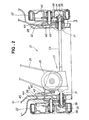
- the drive unit 21 includes a driving pulley 24 mounted on the output shaft 17, a driven pulley 26, a belt 25 running between the driving pulley 24 and the driven pulley 26, a drive reduction gear 27 mounted to the body frame 12 and connected to the driven pulley 26, right and left wheel support means 28 (see FIG. 2 ) mounted to the body frame 12, right and left tubular housings 31 (see FIG. 2 ) fitted to the body frame 12, and right and left power transmission mechanisms 32, 32 (see FIG. 2 ) connected to the drive reduction gear 27.
- the drive shaft 33 is provided between the right and left power transmission mechanisms 32 with the drive reduction gear 27 interposed therebetween.
- the opposite ends of the drive shaft 33 are rotatably fitted in the right and left tubular housings 31, respectively.
- a first end (right end) portion 34 of the drive shaft 33 is projected from the right housing 31.
- a second end (left end) portion 37 of the drive shaft 33 is projected from the left housing 31.
- Right and left driven members 36 are mounted on the first end portion 34 and the second end portion 37 of the drive shaft 33, respectively, with right and left one-way clutches 35 interposed therebetween.
- the right and left power transmission mechanisms 32 transmit power from the drive shaft 33, through the driven members 36, 36, to the right and left drive wheels 22, 22 provided on the wheel support means 28, 28.
- Reference numeral 38 denotes a wheel of the drive wheels 22.
- Each wheel support means 28 includes a bracket 42 fixed at its first end to the housing 31 and fitted at its second end to the body frame 12, an axle 43 fixed to the bracket 42, a cover 44 mounted to the axle 43 and the housing 31, and a gear 45 mounted on a boss of the wheel 38, meshing with the driven member 36 provided with the one-way clutch 35.
- the one-way clutch 35 includes a swinging clutch portion 53, a clutch portion housing groove 54, a collar 55, a slit 56, engaging grooves 57, and a sealing member 61.
- the swinging clutch portion 53 has a keyhole-section shape, consisting of a cylindrical portion 51 extending in an axially longitudinal direction (directions of arrows "a") of the drive shaft 33 and a projecting portion 52 extending from the periphery of the cylindrical portion 51.
- the clutch portion housing groove 54 is formed in the drive shaft 33 for housing the cylindrical portion 51 of the swinging clutch portion 53, holding the swinging clutch portion 53 swingably.
- the collar 55 is fitted onto the drive shaft 33 rotatably (in directions of arrows "b").
- the collar 55 has the slit 56 formed in an axially longitudinal direction so that the projecting portion 52 of the swinging clutch portion 53 can project therefrom and retract thereinto.
- the engaging grooves 57 are formed in the driven member 36 for engagement with the projecting portion 52.
- the sealing member 61 is interposed between the housing 31 and the collar 55 for preventing the collar 55 from rotating together with the rotation of the drive shaft 33.
- the sealing member 61 is an oil seal, and is desirably provided with a spring 63.
- the drive shaft 33 is rotatably supported by the housing 31 via a bearing 64.
- Reference numerals 65, 65 denote snap rings, and 66, 66, flat rings.
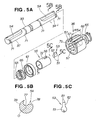
- FIG. 5A illustrates in explosion the power transmission mechanism 32 of the present invention
- FIG. 5B illustrates in section the first end portion 34 of the drive shaft 33 along line 5B ⁇ 5B in FIG. 5A
- FIG. 5C illustrates the swinging clutch portion 53 when viewed along line 5C ⁇ 5C in FIG. 5A .
- the drive shaft 33 has the clutch portion housing groove 54 and circumferential grooves 71, 71 formed in the first end portion 34, and the clutch portion housing groove 54 and circumferential grooves 71, 71 formed in the second end portion 37.
- the snap rings 65, 65 are fitted into the circumferential grooves 71, 71, respectively.
- a steel material defined by S48C in JIS is used, for example.
- the collar 55 has a tubular body 72 of a steel pipe with a given thickness "t,” having at its first end portion the slit 56 formed in an axially longitudinal direction of the tubular body 72. Slitting facilitates fabrication, and also facilitates the assembly of the swinging clutch portion 53.
- a spur gear is used, and the facewidth of the spur gear is set at Wt.
- the driven member 36 may be other than a spur gear, and, for example, a pulley may alternatively be used.
- a sintered material is used, for example.
- Each engaging groove 57 is formed in an inner peripheral surface 75 of the driven member 36 with a length approximately half the facewidth Wt.
- the three engaging grooves 57 are formed in the inner peripheral surface 75 at equal intervals, but the number thereof can be any.
- the clutch portion housing groove 54 consists of a circular portion 77 into which the cylindrical portion 51 of the swinging clutch portion 53 is fitted, and a linear portion 78 extending continuously from the circular portion 77 to the periphery of the drive shaft 33.
- the clutch portion housing groove 54 is formed at a position radially offset from the center O of the drive shaft 33, serving as a cam groove.
- the swinging clutch portion 53 has a keyhole-section shape, consisting of the cylindrical portion 51 and the projecting portion 52 extending from the cylindrical portion 51, as described above.
- the projecting portion 52 has inclined portions 81, 81 formed at its distal end portion. The formation of the inclined portions 81, 81 makes it possible to reduce the depth "h" of each engaging groove 57 to be engaged with the projecting portion 52 (see FIG. 4 ) to reduce the size of the engaging grooves 57, and also makes it possible to form the corners of the engaging grooves 57 at an obtuse angle to facilitate forming of the engaging grooves 57.
- a sintered material is used for the material of the swinging clutch portion 53.
- FIGS. 6A to 6E illustrate the one-way clutch 35 from the state of not transmitting a driving force from the drive shaft 33 to the driven member 36 (non-engagement state) to the state of transmitting a driving force (engagement state).
- the one-way clutch 35 is in a non-engagement state, not transmitting a driving force from the drive shaft 33 to the driven member 36.
- the swinging clutch portion 53 of the one-way clutch 35 moves down at angle ⁇ 1 to be within the clutch portion housing groove 54, and at the same time, the distal end portion of the projecting portion 52 of the clutch portion 53 retracts into the slit 56 of the collar 55.
- the distal end portion of the projecting portion 52 does not engage any engaging groove 57, and the one-way clutch 35 does not transmit power to the driven member 36. That is, the projecting portion 52 in a linear shape of the swinging clutch portion 53 lies down in contact with the linear portion 78 of the clutch portion housing groove 54.
- the drive shaft 33 continuously rotates the collar 55 via the swinging clutch portion 53. While the drive shaft 33 and the collar 55 rotate together, the driven member 36 does not rotate and continues stationary.
- the cylindrical portion 51 of the swinging clutch portion 53 is rotated by the collar 55 at angle ⁇ 2 as shown by arrow "h," and the projecting portion 52 is detached from the linear portion 78 of the clutch portion housing groove 54, raised by angle ⁇ 2. That is, the collar 55 rotating more slowly than the drive shaft 33 raises the swinging clutch portion 53 to bring the clutch 35 into an engaged state.
- the one-way clutch 35 is in a state of being able to transmit a driving force (engagement state), and a driving force is transmitted from the drive shaft 33 to the driven member 36 as shown by arrow "j." With the rotation of the drive shaft 33, the driven member 36 also rotates.
- the one-way clutch 35 has an advantage that, as shown in FIG. 6C , the projecting portion 52 can be swung by angle 02, pivoting on the cylindrical portion 51 of the swinging clutch portion 53, and thereby ensuring transmission of power without impacts.
- the one-way clutch 35 has the sealing member 61 interposed between the housing 31 and the collar 55 as shown in FIG. 3 , thus facilitating the provision of rotation resistance to the collar 55 with the sealing member 61 of a simple configuration.
- FIGS. 7A to 7D illustrate the operation of the one-way clutch 35 when the lawn mower 11 (see FIG. 1 ) is turned when being driven by the engine 15 (see FIG. 1 ), that is, the operation of the one-way clutch 35 from a state of transmitting a driving force (engagement state) to a state of not transmitting a driving force (non-engagement state).
- these figures show those states with the drive shaft 33 not rotated.
- the number of revolutions of the driven member 36 is increased from Ng to Nf relative to the number of revolutions Nd of the drive shaft 33 (Nf > Nd), and the engaging groove 57 of the driven member 36 rotates without interfering with the projecting portion 52, allowing the driven member 36 to rotate faster than the drive shaft 33.
- the operation of increasing the number of revolutions of the driven member 36 is done by rotating the drive wheel 22 (see FIG. 1 ) by pushing the operating handle 14 (see FIG. 1 ).
- the driven member 36 can be rotated in a direction (direction of arrow "j"), here, a forward direction, by a small force.
- the driven member 36 rotates in a direction in the same manner. That is, the drive wheel 22 (see FIG. 1 ) can be rotated in a direction.
- an operator can move the lawn mower 11 forward by a small force.
- FIGS. 8A to 8C schematically illustrate straight traveling and turning states of the lawn mower 11.
- the lawn mower 11 shown in FIG. 8A is advanced by an operator manually pushing the lawn mower 11 without starting the engine 15. As described with FIGS. 7A to 7D , since the one-way clutches 35 do not engage the driven members 36 and the drive wheels 22, 22 rotate freely, the lawn mower 11 can be easily pushed and moved forward by hand.
- FIG. 8B illustrates a state where the engine 15 is started. Since the driving force of the engine 15 is transmitted to the right and left drive wheels 22, 22 via the one-way clutches 35, 35 as described with FIGS. 6A to 6E , an operator can cause the lawn mower 11 to move straight.
- the power transmission mechanisms of the present invention are exemplarily applied to a lawn mower for description, but are also applicable to one-wheel to four-wheel carriers, cultivators and snow plows.
Landscapes
- Engineering & Computer Science (AREA)
- General Engineering & Computer Science (AREA)
- Mechanical Engineering (AREA)
- Harvester Elements (AREA)
- Mechanical Operated Clutches (AREA)
- One-Way And Automatic Clutches, And Combinations Of Different Clutches (AREA)
- Gear Transmission (AREA)
Claims (2)
- Kraftübertragungsmechanismus, umfassend:eine Antriebswelle (33), die an Gehäusen (31) drehbar gelagert ist,wobei zumindest ein Endabschnitt der Antriebswelle von dem entsprechenden Gehäuse vorsteht; undein angetriebenes Element (36), das an dem vorstehenden einen Endabschnitt der Antriebswelle mittels einer dazwischen eingefügten Einwegkupplung (35) angebracht ist;wobei die Einwegkupplung umfasst:einen Schwingkupplungsabschnitt (53) mit schlüssellochförmigem Querschnitt, enthaltend einen zylindrischen Abschnitt (51), der sich axial der Antriebswelle erstreckt, und einen vorstehenden Abschnitt (52), der sich von dem zylindrischen Abschnitt weg erstreckt; Kupplungsabschnitt-Aufnahmenut (54), die in der Antriebswelle (33) ausgebildet ist, zur Aufnahme des zylindrischen Abschnitts (51), wobei diese den Schwingkupplungsabschnitt (53) um den zylindrischen Abschnitt herum schwingbar hält;einen Kragen (55), der drehbar auf die Antriebswelle aufgesetzt ist und einen Schlitz (56) aufweist, der derart geformt ist, dass ein distaler Endabschnitt des vorstehenden Abschnitts (52) daraus ausfahren und dorthin einfahren kann;zumindest eine Eingriffsnut (57), die in einer Innenumfangsoberfläche des angetriebenen Elements (36) ausgebildet ist, zum Eingriff mit dem distalen Endabschnitt des vorstehenden Abschnitts (52); undein Dichtungselement (61), das zwischen dem Gehäuse (31) und dem Kragen eingefügt ist, um eine Drehung des Kragens (55) zusammen mit Drehung der Antriebswelle (33) zu verhindern,worin, wenn der Schwingkupplungsabschnitt durch den Kragen angehoben wird, der sich langsamer dreht als sich die Antriebswelle dreht, der distale Endabschnitt des vorstehenden Abschnitts von einem Umfang des Schlitzes vorsteht, um hierdurch in die Eingriffsnut einzugreifen, und wenn der Schwingkupplungsabschnitt nach unten gelegt wird, der distale Endabschnitt des vorstehenden Abschnitts in den Schlitz einfährt, um sich hierdurch von der Eingriffsnut zu lösen.
- Kraftübertragungsmechanismus nach Anspruch 1, worin die in der Antriebswelle (33) ausgebildete Kupplungsabschnitt-Aufnahmenut (54) an einer Position vorgesehen ist, die von einer Wellenmitte (O) oder Antriebswelle radial versetzt ist.
Applications Claiming Priority (2)
| Application Number | Priority Date | Filing Date | Title |
|---|---|---|---|
| JP2003365222 | 2003-10-24 | ||
| JP2003365222A JP2005127448A (ja) | 2003-10-24 | 2003-10-24 | 動力伝達機構 |
Publications (3)
| Publication Number | Publication Date |
|---|---|
| EP1526300A2 EP1526300A2 (de) | 2005-04-27 |
| EP1526300A3 EP1526300A3 (de) | 2007-03-28 |
| EP1526300B1 true EP1526300B1 (de) | 2008-07-09 |
Family
ID=34386551
Family Applications (1)
| Application Number | Title | Priority Date | Filing Date |
|---|---|---|---|
| EP04255588A Expired - Lifetime EP1526300B1 (de) | 2003-10-24 | 2004-09-15 | Kraftübertragungsmechanismus |
Country Status (7)
| Country | Link |
|---|---|
| US (1) | US7073648B2 (de) |
| EP (1) | EP1526300B1 (de) |
| JP (1) | JP2005127448A (de) |
| CN (2) | CN2766107Y (de) |
| AU (1) | AU2004218605B2 (de) |
| CA (1) | CA2482218C (de) |
| DE (1) | DE602004014873D1 (de) |
Families Citing this family (12)
| Publication number | Priority date | Publication date | Assignee | Title |
|---|---|---|---|---|
| JP2005127448A (ja) * | 2003-10-24 | 2005-05-19 | Honda Motor Co Ltd | 動力伝達機構 |
| JP4776435B2 (ja) | 2006-05-24 | 2011-09-21 | 本田技研工業株式会社 | 自走式作業機の走行駆動機構 |
| DK177273B1 (da) * | 2008-02-11 | 2012-09-10 | Hh Patent As | Kobling |
| JP5041248B2 (ja) * | 2008-10-23 | 2012-10-03 | アイシン精機株式会社 | セルフロッククラッチ |
| US8657693B2 (en) | 2009-12-03 | 2014-02-25 | Toyota Jidosha Kabushiki Kaisha | Torsional shock absorbing apparatus |
| KR101735465B1 (ko) * | 2015-11-25 | 2017-05-15 | 현대다이모스(주) | 듀얼 클러치의 기어용 액추에이터 |
| JP6230642B2 (ja) * | 2016-03-17 | 2017-11-15 | 本田技研工業株式会社 | 歩行型芝刈機 |
| US10550899B2 (en) * | 2018-03-30 | 2020-02-04 | Honda Motor Co. | Transmission for wheeled machine |
| CN113819158B (zh) * | 2021-09-29 | 2023-08-15 | 延锋汽车智能安全系统有限责任公司 | 单向离合器和安全带卷收器 |
| CN113819157B (zh) * | 2021-09-29 | 2023-04-28 | 延锋汽车智能安全系统有限责任公司 | 单向离合器和安全带卷收器 |
| CN117128257A (zh) | 2022-05-18 | 2023-11-28 | 米沃奇电动工具公司 | 离合器机构 |
| CN117678782B (zh) * | 2023-12-12 | 2025-11-25 | 东北林业大学 | 一种豆粕粗精两级粉碎及成形装置 |
Family Cites Families (7)
| Publication number | Priority date | Publication date | Assignee | Title |
|---|---|---|---|---|
| JPS60227025A (ja) * | 1984-04-25 | 1985-11-12 | Asahi Optical Co Ltd | クラツチ装置 |
| US4909365A (en) | 1987-07-02 | 1990-03-20 | The Toro Company | Freewheeling clutch and implement employing same |
| US4928905A (en) * | 1989-05-01 | 1990-05-29 | Arena Recreations (Toronto) Limited | One-way clutch assembly |
| US6354414B1 (en) * | 1999-06-16 | 2002-03-12 | Honda Giken Kogyo Kabushiki Kaisha | Clutch mechanism |
| JP4382969B2 (ja) | 1999-06-16 | 2009-12-16 | 本田技研工業株式会社 | クラッチ機構 |
| US6575280B2 (en) * | 2001-06-11 | 2003-06-10 | White Consolidated Industries, Inc. | Freewheeling bi-directional clutch |
| JP2005127448A (ja) * | 2003-10-24 | 2005-05-19 | Honda Motor Co Ltd | 動力伝達機構 |
-
2003
- 2003-10-24 JP JP2003365222A patent/JP2005127448A/ja active Pending
-
2004
- 2004-09-15 DE DE602004014873T patent/DE602004014873D1/de not_active Expired - Lifetime
- 2004-09-15 EP EP04255588A patent/EP1526300B1/de not_active Expired - Lifetime
- 2004-09-21 CA CA2482218A patent/CA2482218C/en not_active Expired - Fee Related
- 2004-09-24 US US10/949,954 patent/US7073648B2/en not_active Expired - Fee Related
- 2004-10-04 AU AU2004218605A patent/AU2004218605B2/en not_active Ceased
- 2004-10-22 CN CNU2004201049483U patent/CN2766107Y/zh not_active Expired - Lifetime
- 2004-10-22 CN CNB200410087719XA patent/CN1325815C/zh not_active Expired - Fee Related
Also Published As
| Publication number | Publication date |
|---|---|
| DE602004014873D1 (de) | 2008-08-21 |
| CN1325815C (zh) | 2007-07-11 |
| CA2482218A1 (en) | 2005-04-24 |
| US7073648B2 (en) | 2006-07-11 |
| CN2766107Y (zh) | 2006-03-22 |
| JP2005127448A (ja) | 2005-05-19 |
| CA2482218C (en) | 2010-07-27 |
| EP1526300A3 (de) | 2007-03-28 |
| US20050087418A1 (en) | 2005-04-28 |
| AU2004218605A1 (en) | 2005-05-12 |
| EP1526300A2 (de) | 2005-04-27 |
| CN1609469A (zh) | 2005-04-27 |
| AU2004218605B2 (en) | 2011-01-27 |
Similar Documents
| Publication | Publication Date | Title |
|---|---|---|
| EP1526300B1 (de) | Kraftübertragungsmechanismus | |
| CN108700128B (zh) | 用于驱动轮轴的具有外弹簧的双向超越离合器 | |
| EP0782820B1 (de) | Getriebe für selbstfahrenden Geh-Rasenmäher | |
| CN111788406B (zh) | 轮式机器的传动装置 | |
| CA2499571A1 (en) | Bi-directional overrunning clutch for a primary drive axle | |
| EP3959449B1 (de) | Getriebekasten und motor mit einem solchen getriebekasten | |
| EP0298016B1 (de) | Freilaufkupplung und Werkzeug, in dem dieselbe angewendet wird | |
| US6354414B1 (en) | Clutch mechanism | |
| US6575280B2 (en) | Freewheeling bi-directional clutch | |
| JP2000170856A (ja) | 作業機の動力伝達装置 | |
| JP3862360B2 (ja) | 一方向クラッチ | |
| EP0940232A3 (de) | Klauenkupplung für eine Kettensäge | |
| US8197368B2 (en) | Transmission system for a self-propelled vehicle with variable travel speed, its control device, and vehicle equipped with such a transmission system | |
| US7070035B2 (en) | Two-way coupling apparatus and method | |
| JP3294101B2 (ja) | 苗植付機構 | |
| JP2001059531A (ja) | クラッチ機構 | |
| JP2678987B2 (ja) | 自走式作業機の変速機構を含む動力伝達装置 | |
| EP4209690B1 (de) | Kupplung und arbeitsmaschine damit | |
| JP2011115067A (ja) | 歩行型作業機 | |
| JPS62441Y2 (de) | ||
| JP3832958B2 (ja) | 携帯式刈払機 | |
| JPS6223304Y2 (de) | ||
| JPH0542574B2 (de) | ||
| JP2023034443A (ja) | 草刈刃の回転方向切替機構、自走草刈機、及び、草刈方法 | |
| JPH10299790A (ja) | 自走式作業機のクラッチ装置 |
Legal Events
| Date | Code | Title | Description |
|---|---|---|---|
| PUAI | Public reference made under article 153(3) epc to a published international application that has entered the european phase |
Free format text: ORIGINAL CODE: 0009012 |
|
| AK | Designated contracting states |
Kind code of ref document: A2 Designated state(s): AT BE BG CH CY CZ DE DK EE ES FI FR GB GR HU IE IT LI LU MC NL PL PT RO SE SI SK TR |
|
| AX | Request for extension of the european patent |
Extension state: AL HR LT LV MK |
|
| PUAL | Search report despatched |
Free format text: ORIGINAL CODE: 0009013 |
|
| AK | Designated contracting states |
Kind code of ref document: A3 Designated state(s): AT BE BG CH CY CZ DE DK EE ES FI FR GB GR HU IE IT LI LU MC NL PL PT RO SE SI SK TR |
|
| AX | Request for extension of the european patent |
Extension state: AL HR LT LV MK |
|
| 17P | Request for examination filed |
Effective date: 20070711 |
|
| GRAP | Despatch of communication of intention to grant a patent |
Free format text: ORIGINAL CODE: EPIDOSNIGR1 |
|
| AKX | Designation fees paid |
Designated state(s): DE FR GB IT |
|
| GRAS | Grant fee paid |
Free format text: ORIGINAL CODE: EPIDOSNIGR3 |
|
| GRAA | (expected) grant |
Free format text: ORIGINAL CODE: 0009210 |
|
| AK | Designated contracting states |
Kind code of ref document: B1 Designated state(s): DE FR GB IT |
|
| REG | Reference to a national code |
Ref country code: GB Ref legal event code: FG4D |
|
| REF | Corresponds to: |
Ref document number: 602004014873 Country of ref document: DE Date of ref document: 20080821 Kind code of ref document: P |
|
| PLBE | No opposition filed within time limit |
Free format text: ORIGINAL CODE: 0009261 |
|
| STAA | Information on the status of an ep patent application or granted ep patent |
Free format text: STATUS: NO OPPOSITION FILED WITHIN TIME LIMIT |
|
| 26N | No opposition filed |
Effective date: 20090414 |
|
| PGFP | Annual fee paid to national office [announced via postgrant information from national office to epo] |
Ref country code: FR Payment date: 20100921 Year of fee payment: 7 Ref country code: IT Payment date: 20100918 Year of fee payment: 7 |
|
| PGFP | Annual fee paid to national office [announced via postgrant information from national office to epo] |
Ref country code: GB Payment date: 20100916 Year of fee payment: 7 |
|
| PGFP | Annual fee paid to national office [announced via postgrant information from national office to epo] |
Ref country code: DE Payment date: 20100908 Year of fee payment: 7 |
|
| GBPC | Gb: european patent ceased through non-payment of renewal fee |
Effective date: 20110915 |
|
| PG25 | Lapsed in a contracting state [announced via postgrant information from national office to epo] |
Ref country code: IT Free format text: LAPSE BECAUSE OF NON-PAYMENT OF DUE FEES Effective date: 20110915 |
|
| REG | Reference to a national code |
Ref country code: FR Ref legal event code: ST Effective date: 20120531 |
|
| PG25 | Lapsed in a contracting state [announced via postgrant information from national office to epo] |
Ref country code: DE Free format text: LAPSE BECAUSE OF NON-PAYMENT OF DUE FEES Effective date: 20120403 |
|
| REG | Reference to a national code |
Ref country code: DE Ref legal event code: R119 Ref document number: 602004014873 Country of ref document: DE Effective date: 20120403 |
|
| PG25 | Lapsed in a contracting state [announced via postgrant information from national office to epo] |
Ref country code: FR Free format text: LAPSE BECAUSE OF NON-PAYMENT OF DUE FEES Effective date: 20110930 Ref country code: GB Free format text: LAPSE BECAUSE OF NON-PAYMENT OF DUE FEES Effective date: 20110915 |