EP3959449B1 - Getriebekasten und motor mit einem solchen getriebekasten - Google Patents
Getriebekasten und motor mit einem solchen getriebekasten Download PDFInfo
- Publication number
- EP3959449B1 EP3959449B1 EP20726221.3A EP20726221A EP3959449B1 EP 3959449 B1 EP3959449 B1 EP 3959449B1 EP 20726221 A EP20726221 A EP 20726221A EP 3959449 B1 EP3959449 B1 EP 3959449B1
- Authority
- EP
- European Patent Office
- Prior art keywords
- shaft
- ramps
- clutch
- clutch mechanism
- dog
- Prior art date
- Legal status (The legal status is an assumption and is not a legal conclusion. Google has not performed a legal analysis and makes no representation as to the accuracy of the status listed.)
- Active
Links
- 230000005540 biological transmission Effects 0.000 title claims description 54
- 241000282472 Canis lupus familiaris Species 0.000 claims description 147
- 230000007246 mechanism Effects 0.000 claims description 146
- 229910003460 diamond Inorganic materials 0.000 claims description 7
- 239000010432 diamond Substances 0.000 claims description 7
- 230000002093 peripheral effect Effects 0.000 claims description 6
- 230000000295 complement effect Effects 0.000 claims description 5
- 230000008878 coupling Effects 0.000 claims 1
- 238000010168 coupling process Methods 0.000 claims 1
- 238000005859 coupling reaction Methods 0.000 claims 1
- 230000033001 locomotion Effects 0.000 description 14
- 238000005096 rolling process Methods 0.000 description 7
- 238000006073 displacement reaction Methods 0.000 description 6
- 230000007704 transition Effects 0.000 description 5
- 238000000926 separation method Methods 0.000 description 3
- 230000009849 deactivation Effects 0.000 description 2
- 230000009471 action Effects 0.000 description 1
- 210000000078 claw Anatomy 0.000 description 1
- 238000010276 construction Methods 0.000 description 1
- 238000004519 manufacturing process Methods 0.000 description 1
- 238000000034 method Methods 0.000 description 1
- 230000008569 process Effects 0.000 description 1
- 230000009467 reduction Effects 0.000 description 1
Images


Classifications
-
- F—MECHANICAL ENGINEERING; LIGHTING; HEATING; WEAPONS; BLASTING
- F16—ENGINEERING ELEMENTS AND UNITS; GENERAL MEASURES FOR PRODUCING AND MAINTAINING EFFECTIVE FUNCTIONING OF MACHINES OR INSTALLATIONS; THERMAL INSULATION IN GENERAL
- F16D—COUPLINGS FOR TRANSMITTING ROTATION; CLUTCHES; BRAKES
- F16D41/00—Freewheels or freewheel clutches
- F16D41/18—Freewheels or freewheel clutches with non-hinged detent
- F16D41/185—Freewheels or freewheel clutches with non-hinged detent the engaging movement having an axial component
-
- F—MECHANICAL ENGINEERING; LIGHTING; HEATING; WEAPONS; BLASTING
- F16—ENGINEERING ELEMENTS AND UNITS; GENERAL MEASURES FOR PRODUCING AND MAINTAINING EFFECTIVE FUNCTIONING OF MACHINES OR INSTALLATIONS; THERMAL INSULATION IN GENERAL
- F16D—COUPLINGS FOR TRANSMITTING ROTATION; CLUTCHES; BRAKES
- F16D7/00—Slip couplings, e.g. slipping on overload, for absorbing shock
- F16D7/04—Slip couplings, e.g. slipping on overload, for absorbing shock of the ratchet type
- F16D7/042—Slip couplings, e.g. slipping on overload, for absorbing shock of the ratchet type with at least one part moving axially between engagement and disengagement
- F16D7/044—Slip couplings, e.g. slipping on overload, for absorbing shock of the ratchet type with at least one part moving axially between engagement and disengagement the axially moving part being coaxial with the rotation, e.g. a gear with face teeth
-
- A—HUMAN NECESSITIES
- A01—AGRICULTURE; FORESTRY; ANIMAL HUSBANDRY; HUNTING; TRAPPING; FISHING
- A01D—HARVESTING; MOWING
- A01D34/00—Mowers; Mowing apparatus of harvesters
- A01D34/01—Mowers; Mowing apparatus of harvesters characterised by features relating to the type of cutting apparatus
- A01D34/412—Mowers; Mowing apparatus of harvesters characterised by features relating to the type of cutting apparatus having rotating cutters
- A01D34/63—Mowers; Mowing apparatus of harvesters characterised by features relating to the type of cutting apparatus having rotating cutters having cutters rotating about a vertical axis
- A01D34/67—Mowers; Mowing apparatus of harvesters characterised by features relating to the type of cutting apparatus having rotating cutters having cutters rotating about a vertical axis hand-guided by a walking operator
- A01D34/68—Mowers; Mowing apparatus of harvesters characterised by features relating to the type of cutting apparatus having rotating cutters having cutters rotating about a vertical axis hand-guided by a walking operator with motor driven cutters or wheels
- A01D34/6806—Driving mechanisms
- A01D34/6812—Braking or clutching mechanisms
-
- F—MECHANICAL ENGINEERING; LIGHTING; HEATING; WEAPONS; BLASTING
- F16—ENGINEERING ELEMENTS AND UNITS; GENERAL MEASURES FOR PRODUCING AND MAINTAINING EFFECTIVE FUNCTIONING OF MACHINES OR INSTALLATIONS; THERMAL INSULATION IN GENERAL
- F16D—COUPLINGS FOR TRANSMITTING ROTATION; CLUTCHES; BRAKES
- F16D11/00—Clutches in which the members have interengaging parts
- F16D11/14—Clutches in which the members have interengaging parts with clutching members movable only axially
-
- F—MECHANICAL ENGINEERING; LIGHTING; HEATING; WEAPONS; BLASTING
- F16—ENGINEERING ELEMENTS AND UNITS; GENERAL MEASURES FOR PRODUCING AND MAINTAINING EFFECTIVE FUNCTIONING OF MACHINES OR INSTALLATIONS; THERMAL INSULATION IN GENERAL
- F16D—COUPLINGS FOR TRANSMITTING ROTATION; CLUTCHES; BRAKES
- F16D41/00—Freewheels or freewheel clutches
- F16D41/12—Freewheels or freewheel clutches with hinged pawl co-operating with teeth, cogs, or the like
- F16D41/16—Freewheels or freewheel clutches with hinged pawl co-operating with teeth, cogs, or the like the action being reversible
-
- A—HUMAN NECESSITIES
- A01—AGRICULTURE; FORESTRY; ANIMAL HUSBANDRY; HUNTING; TRAPPING; FISHING
- A01D—HARVESTING; MOWING
- A01D34/00—Mowers; Mowing apparatus of harvesters
- A01D34/01—Mowers; Mowing apparatus of harvesters characterised by features relating to the type of cutting apparatus
- A01D34/412—Mowers; Mowing apparatus of harvesters characterised by features relating to the type of cutting apparatus having rotating cutters
- A01D34/63—Mowers; Mowing apparatus of harvesters characterised by features relating to the type of cutting apparatus having rotating cutters having cutters rotating about a vertical axis
- A01D34/67—Mowers; Mowing apparatus of harvesters characterised by features relating to the type of cutting apparatus having rotating cutters having cutters rotating about a vertical axis hand-guided by a walking operator
- A01D34/68—Mowers; Mowing apparatus of harvesters characterised by features relating to the type of cutting apparatus having rotating cutters having cutters rotating about a vertical axis hand-guided by a walking operator with motor driven cutters or wheels
- A01D34/69—Mowers; Mowing apparatus of harvesters characterised by features relating to the type of cutting apparatus having rotating cutters having cutters rotating about a vertical axis hand-guided by a walking operator with motor driven cutters or wheels with motor driven wheels
Definitions
- the present invention relates to a transmission box, as well as a rolling machine equipped with such a transmission box.
- a transmission housing comprising housed at least partially inside said housing, a so-called output shaft made in one piece or in at least two coaxial shaft sections mounted free to rotate relative to each other.
- a rotary motor member mounted freely in rotation on said shaft, a system for driving said rotary motor member in rotation according to a first direction of rotational drive called forward gear and in a second direction of rotational drive said reverse gear and, arranged between the shaft or each of the shaft sections and the rotating motor member, a clutch mechanism, the or each clutch mechanism having a disengaged state and an engaged state, the shaft or each shaft section being, in the disengaged state of the corresponding clutch mechanism, free to rotate in any of its directions of rotation, the or each so-called automatic clutch mechanism being configured for, in the state driven in rotation of the rotating motor member in the first rotational drive direction called forward, passing from the disengaged state to the engaged state when the speed of rotation of said rotating motor rotating member is greater than that of the shaft or of said shaft section with which the clutch mechanism is capable of
- Such a transmission housing incorporates a so-called automatic clutch which does not require, for its operation, a dedicated control member, such as a fork, as is the case in traditional clutches.
- An object of the invention is to provide a transmission box whose design allows increased performance without harming the compactness and simplicity of the box.
- the subject of the invention is a transmission housing comprising housed at least partially inside said housing, a so-called output shaft made in one piece or in at least two coaxial shaft sections, a member rotary said motor mounted free to rotate on said shaft, a system for driving said rotary motor member in rotation according to a first direction of rotational drive called forward and according to a second direction of rotational drive called reverse and, arranged between the shaft or each of the shaft sections and the rotating motor member, a clutch mechanism, the or each clutch mechanism housed inside the housing having a disengaged state and an engaged state, the shaft or each shaft section being, in the disengaged state of the corresponding clutch mechanism, free to rotate in any of its directions of rotation, the or each so-called automatic clutch mechanism being configured for, at the state driven in rotation of the rotary motor member in the first rotational drive direction called forward, passing from the disengaged state to the engaged state when the speed of rotation of said rotary motor member is greater than that of the shaft or of said shaft section with which the clutch mechanism is capable of cooperating
- the or at least one of the clutch mechanisms comprises a movable part on the shaft or the shaft section between a disengaged position and an engaged position, said part drivable in rotation by the rotary motor member being configured to pass from the engaged position corresponding to the engaged state of the clutch mechanism to the disengaged position corresponding to the disengaged state of the clutch mechanism by bearing contact with the rotary member engine.
- This design makes it possible to retain a particularly simple architecture and operation of the clutch mechanism without requiring the presence of a quick-wear part, such as a spring, in particular for the return to the disengaged position.
- the movable part which can be driven in rotation by the rotary motor member is therefore configured to pass from the engaged position to the disengaged position by axial movement along the shaft or the shaft section carrying said clutch mechanism. This axial displacement can take place by simple bearing contact of the moving part with the rotating motor member.
- the moving part of the clutch mechanism is configured to pass from the disengaged position to the position engaged by bearing contact with the rotating motor member.
- the moving part of the clutch mechanism is a part arranged between a so-called fixed dog part mounted integral in rotation with the shaft or the shaft section associated with the clutch mechanism and part of the rotary engine member, this moving part of the clutch mechanism being a moving part axially on said shaft or said shaft section between a position close to said fixed dog corresponding to the engaged state of the clutch mechanism and a separated position of the fixed dog corresponding to the disengaged state of the clutch mechanism.
- the moving part of the clutch mechanism is a part permanently braked by a brake with permanent action on the angular speed of said moving part.
- the brake is mounted fixed in rotation inside the casing.
- the moving part of the clutch mechanism is a hollow plate and the plate and the fixed dog clutch are respectively equipped with teeth for securing in rotation the plate and the fixed dog clutch in the close state of the fixed dog clutch plate.
- the moving part of the clutch mechanism is a plate equipped with ramps configured to cooperate by bearing contact with complementary ramps provided on the rotary motor member for axial movement of the plate in the direction of an approximation or a separation of the fixed jaw integral in rotation with the shaft or the shaft section associated with the clutch mechanism.
- the ramps of the plate and of the rotary motor member are each organized into a first and a second series of ramps, with the ramps of one of the series active in forward operation and the ramps of the other series active in reverse, these ramps of each series of ramps comprising a plurality of sets of ramps, each set of ramps or of a series of ramps of the rotary motor member comprising at least two ramps, these ramps of the rotary motor member cooperating with one , with one of the ramps of a set of ramps of a series of ramps of the plate for axial displacement of the plate in the direction of bringing the fixed dog closer corresponding to the engaged position, the other, with the another of the ramps of said set of ramps of a series of ramps of the plate for an axial movement of the plate in the direction of a spacing of the fixed jaw corresponding to the disengaged position.
- the ramps of a set of ramps of the first series of ramps of the platform form with the ramps of a set of ramps of the second series of ramps of the platform a diamond, these ramps being preferably helical ramps with the same helix pitch.
- the movable part of the or one of the clutch mechanisms and the rotary motor member are for driving the movable part in rotation by the rotary motor member each provided with teeth, each tooth of the moving part being mounted with clearance in the space between two teeth of the rotating motor member.
- the or each clutch mechanism comprises two so-called mobile dogs, one for forward gear, the other for reverse gear, carried by the rotary motor member, a so-called dog dog element fixed integral in rotation with the shaft or the shaft section carrying the said clutch mechanism and a dog clutch pilot, the said dog clutch pilot mounted coaxially and free to rotate on the shaft or the shaft section which carries it, being a part permanently braked by a brake permanently acting on the angular speed of said dog clutch pilot, this dog clutch pilot being equipped with a guide path for the mobile dogs to selectively allow the passage of each mobile dog from a disengaged state to an engaged state in engagement with the so-called fixed dog clutch element, said dog clutch pilot guide path being configured to allow passage of the moving dog dog forward in the engaged state, in the driven state in rotation of the rotary motor member in the first direction of drive in rotation called forward, when the speed of rotation of said rotating motor member is greater than that of the shaft or of said shaft section with which the clutch mechanism is capable of cooperating, and the passage of the movable
- each movable dog takes the form of a pivoting lever mounted so as to be able to pivot around an axis parallel to the shaft or to the shaft sections for the passage of said movable dog from a disengaged state to an engaged state or vice versa.
- said pivoting lever is provided with a finger arranged along or inside the guide path of the dog clutch pilot, this finger being positionable in bearing contact with the element of fixed dog.
- the fixed clutch element takes the form of a ring mounted integral in rotation with the shaft or the shaft section which carries it, said ring being provided with at least two external radial projections, one or the other of said external radial projections forming a bearing abutment for one of the movable dogs in the engaged state of the clutch mechanism, at least part of the external peripheral surface of the ring provided between said external radial projections being configured to form the portion forming the clutch release cam of said fixed dog clutch element.
- the dog clutch pilot takes the form of a rotating part of the plate type through which the shaft or the shaft section which carries it passes, this rotating part being provided with at least one through light forming the guide path of said dog clutch pilot.
- the invention also relates to a rolling self-propelled vehicle with a driver, preferably a walker, such as a lawnmower, comprising a primary drive shaft, wheels and a positionable transmission box between the primary drive shaft and the wheels of the machine, characterized in that the transmission box conforms to that described above.
- the subject of the invention is a transmission housing 1, more particularly intended to be applied to a rolling machine 20, in particular a walk-behind machine.
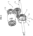
- FIG. 1 shows the application of such a transmission housing 1 to a lawn mower.
- This lawn mower has a rolling frame, the rear wheels of the frame being shown at 21 in the figures.
- the transmission housing 1 here is to transmit a rotational movement to the rear wheels 21 of said machine.
- the transmission case therefore comprises a so-called output shaft 6, made in one piece or in at least two coaxial shaft sections 6A, 6B, mounted free to rotate with respect to each other.
- the shaft 6 or the shaft sections 6A, 6B here form the drive shaft of the wheels 21 of the same pair of wheels of the machine directly or via a reduction.
- This shaft 6 or the shaft sections 6A, 6B pass through the casing 1 and protrude from the latter.
- a rotary member 5 of the motor is rotatably mounted on the shaft 6.
- This rotary member 5 is, in the examples shown, a toothed wheel through which the shaft 6 passes.
- the transmission housing 1 also comprises a system 2 for driving this rotary motor member 5 in rotation.
- This rotation drive system 2 is configured to drive the rotary motor member 5 in rotation in a first direction of rotational drive called forward and in a second direction of opposite rotational drive called reverse.
- This rotational drive system 2 can affect a large number of shapes.
- this rotational drive system 2 comprises an electric motor with two directions of rotation and gears for transmitting the rotational movement of the motor shaft 22 to the rotary motor member 5 .
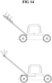
- This electric motor can be controlled in rotation using a single pivoting lever placed on the handlebar of the machine or using a sliding sleeve as illustrated in the figure 14 or using two joysticks as shown in figure 1 .
- a clutch mechanism 3 or 4 is arranged inside the transmission housing 1 between the shaft 6 or each of the shaft sections 6A, 6B and the drive wheel 5 forming the rotating motor member 5 .
- the shaft 6 is made of two coaxial shaft sections 6A, 6B, connected by a connecting element 13 on which said shaft sections are mounted free to rotate in order to be able, in the aligned state, to be driven by relative displacement in rotation.
- the transmission comprises two clutch mechanisms 3 or 4, each arranged between the rotating motor member 5, and a section 6A, 6B of the wheel drive shaft.
- These clutch mechanisms 3 or 4 are capable of transmitting, one, the transmission of the movement of the rotating engine member 5 to the section 6A of the wheel drive shaft, the other, the transmission of the movement of the motor rotary member 5 to the wheel drive shaft section 6B.
- the motor rotary member 5, disposed coaxial with the wheel drive shaft sections is disposed between two clutch mechanisms, each mechanism 3 or 4 clutch being carried at least partially by a wheel shaft section of the same pair of wheels of the machine.
- the shaft 6 is made in one piece and carries only one clutch mechanism.
- the design and operation of the clutch mechanisms between the figure 2 And 3 are the same.
- Each clutch mechanism comprises, independently of its design, an engaged state and a disengaged state.
- the shaft 6 or each shaft section 6A, 6B is, in the disengaged state of the associated clutch mechanism, free to rotate in any of its directions of rotation.
- Each clutch mechanism is a clutch mechanism with two operating directions, that is to say is configured to pass from the disengaged state to the engaged state by driving the rotary motor member 5 according to a first drive direction in rotation called forward and, by driving the rotary motor member 5 in a second direction of drive in rotation called reverse, opposite to the first direction of drive in rotation.
- This clutch is capable of operating when the speed of rotation of the rotary motor member is greater than that of the shaft or of the shaft section carrying said mechanism.
- each clutch mechanism is capable of changing automatically from the engaged state to the disengaged state, both in forward gear and in reverse gear, that is to say the driven state in rotation of the motor rotary member 5 in forward gear when the speed of rotation of the shaft 6 or of the shaft section carrying the clutch mechanism, and driven in rotation in forward gear, is greater than the speed of rotation of the rotary motor member 5, and in the rotationally driven state of the rotary motor member 5 in reverse when, again, the speed of rotation of the shaft 6 or of the shaft section carrying the mechanism clutch, and driven in rotation in reverse, is greater than the speed of rotation of the rotating member 5 motor.
- Such a clutch mechanism is characterized in particular, despite its numerous functionalities, by the absence of a spring as a return means in the disengaged state.
- the transition from the engaged state to the disengaged state is therefore carried out in the absence of an elastic return member, but only by bearing contact of the parts with each other.
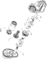
- each clutch mechanism represented and designated by the general reference 3 comprises a movable part 31, axially movable on the shaft or the shaft section which carries it, between a position corresponding to the disengaged state of the clutch mechanism and an engaged position corresponding to the engaged state of the clutch mechanism, by bearing contact with the rotating motor member.
- this movable part 31 is axially movable on the shaft or the shaft section which carries it, by bearing contact with the rotary motor member 5 for the passage from an engaged position to a disengaged position and for the passage from a disengaged position to an engaged position.
- the movable part 31 of the clutch mechanism 3 is a part permanently braked by a brake 8 permanently acting on the angular speed of said movable part 31.
- This brake 8 has here the shape of a U-shaped leaf spring.
- the core of the U is provided with a through hole to be able to slip the brake on the shaft.
- the branches of the U each rest on the peripheral surface of the mobile part 31 which is in the form of a centrally hollowed out circular plate in order to be able to be slipped onto the shaft 6 or the shaft section which carries it.
- This brake 8 is mounted fixed in rotation inside the housing.
- the brake 8 is, for example, provided with two lugs arranged at the level of the branches of the U. These lugs are inserted into grooves made in the housing. This lugs/grooves cooperation allows brake 8 to be immobilized in rotation inside the housing.
- This movable part 31 is disposed between a part 7 called a fixed dog clutch, mounted integral in rotation with the shaft 6 or the shaft section which carries it, and a part of the rotating motor member 5 .
- This so-called fixed dog clutch 7 with respect to the shaft 6 or to the shaft section which carries it also takes the form of a centrally hollowed circular plate.
- the mobile part 31 and the fixed dog clutch 7 are equipped with axial teeth 9, that is to say each time projecting from one face of the plate forming the mobile part 31 or the fixed dog dog 7.
- the teeth 9 of the mobile part 31 and the teeth 9 of the fixed dog dog 7 which each form a crenellation interlock for a rotational connection of the mobile part 31 and the dog clutch 7 fixed.
- the movable part 31 is equipped with ramps 10 configured to cooperate by bearing contact with complementary ramps 11 formed on the rotating motor member 5 .
- the rotating motor member 5 which externally assumes the shape of a toothed wheel is here, for ease of manufacture, made in two parts integral in rotation with each part carrying ramps 11.
- This rotating motor member 5 could, equivalently, have been made in one piece.
- This rotary motor member 5, which takes the form of a toothed wheel with a wheel hub and an outer peripheral toothing, provides an annular space between the hub of the wheel and the outer peripheral toothing of the wheel.
- the hub forms a sleeve on which the moving part 31 can be slipped.
- the ramps 10 of the moving part 31 are arranged inside the recess of the centrally recessed plate forming said moving part 31.
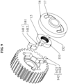
- These ramps 10 of the mobile part 31 are organized in two series of ramps with the ramps 10A active in forward gear and the ramps 10B active in reverse gear.
- These ramps of each series 10A or 10B of ramps comprise a plurality of sets of ramps shown at 10A1 and 10A2 for the series of ramps 10A and at 10B1 and 10B2 for the series of ramps 10B. These sets of ramps are distributed circumferentially on the moving part 31.
- Each set of ramps 10A1, 10A2 or 10B1, 10B2 includes two ramps.
- the ramps 10A1, 10A2 of a set of ramps of the first series of ramps of the plate 31 form with the ramps 10B1, 10B2 of a set of ramps of the second series of ramps of the plate 31 a diamond.
- These ramps 10A1, 10A2, 10B1, 10B2 are preferably helical ramps with an identical helix pitch.
- the ramps 10A1, 10A2 of a set of ramps of the series of ramps 10A of the moving part 31 are arranged on either side of a plane perpendicular to the shaft 6 or to the shaft section 6A or 6B which carries the moving part 31.
- the ramps 10A1 arranged on the same side of the plane are arranged on the same center circle passing through the shaft 6 or the shaft section 6A or 6B which carries the moving part 31. It is the same ramps 10A2 arranged on the other side of the plane.
- the ramps 10A1, 10A2 of a set of ramps of the series of ramps 10A therefore form two adjacent sides of the diamond.
- the ramps 10B1, 10B2 of each set of ramps of the series of ramps 10B of the moving part 31 are arranged on either side of a plane perpendicular to the shaft 6 or to the section of shaft 6A or 6B which carries the mobile part 31.
- the ramps 10B1 arranged on the same side of the plane are arranged on the same center circle passing through the shaft 6 or the shaft section 6A or 6B which carries the moving part 31.
- the ramps 10B1, 10B2 of a set of ramps of the series of ramps 10B therefore form the two other adjacent sides of the diamond.
- the ramps 11 of the motor rotary member 5 are, in the same way, organized into two series of ramps shown at 11A and 11B in the figures, with the ramps 11A1, 11A2 of the series of ramps 11A active in forward operation, that is that is to say in the rotationally driven state of the rotary motor member 5 in the first direction of drive in rotation called forward, and the ramps 11B1, 11B2 of the series of ramps 11B active in reverse, that is to say in the state driven in rotation of the rotary motor member 5 in the second direction of drive in rotation called reverse.
- These ramps 11A and 11B form two circular sawtooth serrations coaxial with the shaft 6 or with the shaft section which carries the rotating motor member 5 and offset axially along said shaft.
- Each sawtooth ramp crenellation formed by ramps of the rotating motor member 5 is formed of an alternation of a ramp of the rotating motor member 5 active in forward operation and a ramp of the member 5 rotary motor active in reverse.
- one of the flanks of a sawtooth of the crenellation is formed by a ramp 11A of the rotating motor member 5 active in forward motion, while the other flank of the sawtooth of the crenellation is formed by a ramp 11B of the rotating motor member 5 active in reverse.
- the ramps 11A of the series of ramps active in forward operation of the motor rotary member 5 comprise a plurality of sets of ramps with each set of ramps comprising two ramps shown at 11A1 and 11A2 in the figures, with one of the ramps, for example the ramp 11A1 of said assembly belonging to one of the ramp notches and the other ramp such as the ramp 11A2 belonging to the other notch.
- the ramps 11B of the series of ramps active in reverse gear of the rotary motor member 5 comprise a plurality of sets of ramps shown at 11B1 and 11B2 in the figures, with one of the ramps, for example the ramp 11B1 of said assembly belonging to one of the ramp crenellations and the other ramp such as ramp 11B2 belonging to the other crenellation.
- the ramps 11A1, 11A2 of a set of ramps of the series of ramps 11A active in forward operation of the motor rotary member 5 cooperate by bearing contact with the ramps 10A1, 10A2 of a set of ramps of the series of ramps 10A active in the forward direction of the mobile part 31 for an axial displacement of the mobile part 31 along the shaft 6 or the shaft section which carries it, in the direction of a ratment or a separation dog clutch 7 fixed.
- the ramps 11A1 of the rotating motor member 5 carried by the sawtooth spline farthest from the fixed dog clutch 7 cooperate by bearing contact with the ramps 10A1 active in forward and which form one side of the diamond of the mobile part 31 for an axial offset of the mobile part 31 in the direction of an approximation of the fixed dog clutch 7 corresponding to the transition from the disengaged state to the engaged state of the mechanism of 'clutch.
- the operation is similar in reverse, the ramps 11B1 and 10B1 cooperating with each other for the transition from the disengaged state to the engaged state and the ramps 11B1 and 10B2 cooperating with each other for switching from the engaged state to the disengaged state.
- the rotary motor member 5 carries all of the ramps necessary for the axial displacement of the movable part 31 in the direction of a clutch or a disengagement. This results in simplicity and mechanical reliability of the assembly.
- the movable part 31 of the clutch mechanism 3 and the rotary motor member 5 are, for the rotational drive of the movable part 31 by the rotary motor member 5, each provided with teeth 12.
- Each tooth 12 of the moving part 31 is mounted with play in the space between two teeth 12 of the rotating motor member 5 .
- These teeth 12 are axial teeth formed on one of the faces of the plate forming the moving part 31 and in the annular space opposite the rotating motor member 5 .
- each clutch mechanism 4 may conform to that shown in figures 8 to 13C .
- each clutch mechanism 4 comprises two movable dogs shown at 141 and 142 in the figures and called, one, dog dog 141 movable forward, the other dog dog 142 movable reverse.
- Each of these mobile jaws is carried by the rotating motor member 5 .
- Said clutch mechanism 4 also comprises a so-called fixed clutch element 15, mounted fixed axially and integral in rotation with the shaft 6 or the shaft section carrying said clutch mechanism 4 and a driver 16 for clutching.
- each leaf spring is threaded on the output shaft and the branches of the U of each leaf spring come into bearing contact on a pilot 16 dog clutch.
- this dog clutch pilot 16 is in the form of a rotating part mounted coaxially and free to rotate on the shaft or the shaft section which carries it.
- This dog clutch pilot 16 is a plate-type rotating part traversed by the shaft 6 or the shaft section which carries it. This rotary part is provided with at least one through-light forming the path 17 for guiding the pilot 16 of interconnection.
- this guide path 17 is made using two through slots made in the dog clutch pilot 16 .
- this dog clutch pilot 16 is equipped with a path 17 for guiding each dog dog 141, 142 mobile to selectively allow the passage of each dog dog 141, 142 mobile from a disengaged state to an engaged state in engagement with the element 15 fixed dog.
- the guide path 17 of the dog clutch pilot 16 is configured to allow the passage of the dog clutch 141 moving forward in the engaged state, in the state driven in rotation of the rotary motor member 5 according to the first direction of drive in rotation known as forward when the speed of said rotary motor member 5 is greater than that of the shaft or of said shaft section with which the clutch mechanism is able to cooperate, and the passage of the jaw 142 movable in reverse in the engaged state, in the state driven in rotation of the rotary motor member 5 according to the second direction of rotational drive called reverse when the speed of rotation of the rotary motor member 5 is greater than that of the shaft 6 or the shaft section 6A, 6B with which the clutch mechanism 4 is able to cooperate.
- each movable jaw 141, 142 carried by the rotating motor member 5 has the form of a pivoting lever mounted so as to pivot about an axis parallel to the shaft 6 or to the shaft sections carrying said mobile dog for the passage of said mobile dog 141, 142 from a disengaged state to an engaged state or vice versa.
- each pivoting lever 1411 or 1421 has a rounded end in the form of a section of cylinder, this rounded end being inserted into a longitudinally split cylindrical housing of the rotating motor member.
- This cylindrical housing opens into one of the faces of the toothed wheel formed by the rotating motor member. The shape of said housing allows a pivoting movement of the lever inside the housing.
- This pivoting lever 1411 or 1421 is provided at its end opposite that forming the pivot with a finger fitting inside the guide path 17, that is to say the opening of the dog clutch pilot.
- This finger is shown at 1412 for the forward moving dog clutch 141 and at 1422 for the reverse moving dog dog 142. This finger can be positioned in bearing contact with the fixed dog dog element 15 in the engaged state of the mobile dog dog.
- the fixed dog clutch element 15 takes the form of a ring 151 mounted integral in rotation with the shaft 6 or the shaft section which carries it.
- This ring 151 is provided with at least two external radial projections 152.
- the rotational mounting of the ring with the shaft which carries it takes place by means of axial splines formed inside the ring, these splines cooperating with ribs of the shaft or of the shaft section carrying the element 15 fixed dog.
- This ring is further provided with two external radial projections 152 forming a bearing abutment for one or the other of the claws 141 or 142 movable in the engaged state of the clutch mechanism 4 depending on the direction of operation, it that is to say rotary drive selected by the rotary motor member.
- the guide path 17 of the dog clutch pilot 16 therefore comprises, at the level of each slot and therefore, for each mobile dog clutch, a first part positioned on a circle of center coinciding with the axis of rotation of the shaft 6 and a second part arranged in the extension of the first part and shaped to develop while tending to approach the axis of rotation of the driver 16 dog clutch.
- first and second parts of a light of the guide path thus allow a finger of a mobile dog, when it moves inside said first and second parts, to pass, by pivoting the lever which carries it, from a spaced position of the element 15 of the fixed dog clutch when it circulates in the first part of the guide path, to a position close to the element 15 of the fixed dog clutch when it circulates in the second part of the guide path , this finger being, in the second part of the guide path, positionable in bearing contact with a radial projection 152 of the fixed dog clutch element 15 to transmit the rotational movement of the rotary motor member 5 to the element 15 of fixed clutch.
- the first and second parts of the guide path of the forward moving dog clutch are made with the first and second parts of the guide path of the reverse moving dog dog in correspondence to allow, when the finger of the forward moving dog dog is placed in the first part of the guide path, that the finger of the reverse-moving dog clutch is arranged in the second part of the guide path and vice versa, the junction between the first and second parts of the guide path formed at the level of each opening of the guide path corresponding to the position taken by each of the fingers in the spaced position of the two fingers of the fixed dog clutch element 15 .
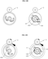
- dog clutch operates as follows: in the disengaged state, the fingers of the forward and reverse dog dogs are each arranged in a position separated from the fixed dog dog element at the junction of the first and second parts of their path 17 guide as shown in Figure 13A .
- the movable forward dog clutch 141 tends to approach the fixed dog dog element 15 by moving the finger of said dog dog in the second part of the guide path 17 provided on the dog clutch driver 16, which is braked.
- the finger of the movable reverse dog clutch 142 moves in the first part of its guide path 17 provided on the dog clutch pilot 16 and remains in the position apart from the element 15 of the fixed dog clutch.
- the operation of the reverse movable dog clutch is similar to that described above for the forward movable dog dog, in the driven state of the motor rotary member 5 in reverse gear.
- the clutch mechanism 4 comprises a release cam which is formed by the fixed jaw element 15.
- the fixed dog clutch element 15 forms a dog clutch release cam 141 which is movable forward in the state driven in rotation in forward travel of the shaft 6 or of the shaft section with which the clutch mechanism cooperates when the speed of rotation of the shaft 6 or of said section 6A, 6B of the shaft is greater than the speed of rotation of the rotating motor member 5 and a clutch release cam 142 movable in reverse in the state driven in reverse rotation of the shaft 6 or of the shaft section with which the clutch mechanism cooperates when the speed of rotation of the shaft or of the shaft section is greater than the speed of rotation of the motor rotary member 5.
- the part forming a declutching cam of the fixed dog clutch element 15 is formed by the part of the outer peripheral surface of the ring 151 constituting the fixed dog dog element 15 provided between the external radial projections 152 .
- the finger of the forward moving dog dog comes into contact with the cam surface of the fixed dog clutch element 15 and is guided in movement by its guide path 17 in the direction of a separation of the fixed dog clutch element 15 to a position in which it extends at the junction of the first and second parts of its guide path 17 formed in the pilot 16 dog clutch.
- the operation is similar for the movable dog clutch in reverse in the driven state of the shaft 6 or of the shaft section carrying the dog element 15 in reverse gear at a speed higher than that of the member. 5 rotary motor.
- the or each clutch mechanism is furthermore, in the engaged state, configured to pass from the engaged state to the disengaged state by reversing the direction of rotation of the rotary motor member 5 over a predetermined angular range.
- This command to reverse the direction of rotation of the motor rotary member over a predetermined angular range can be performed automatically using the motor rotation drive command arranged at the handlebar, for example, when the release of said command.
- releasing the control on the handlebar allows, using a switch or a sensor corresponding to the released position of the control, to automatically send to the motor control unit a command signal for reversing the direction of the motor to generate the drive in rotation of the motor rotary member 5 in an opposite direction over a predetermined angular range in order to return the clutch mechanism to the disengaged state. Beyond this predetermined angular range, continuing to drive the rotating motor member 5 in rotation again causes the clutch mechanism to switch from the disengaged state to the engaged state.
- the casing which at least partially houses all of the elements described above is generally formed of two shells assembled by a parting plane.
- the transmission housing comprises only a single clutch mechanism whose operation is similar to that described for a clutch mechanism fitted to a shaft section.
- the operator For driving a machine equipped with a transmission box of the type described above, the operator need only control the driving direction in forward or reverse direction of the rotating motor member.
- the clutching or disengaging then takes place solely as a function of the relative speeds of the rotating motor member 5 and the shaft 6 or sections 6A, 6B of the shaft.
Landscapes
- Engineering & Computer Science (AREA)
- General Engineering & Computer Science (AREA)
- Mechanical Engineering (AREA)
- Life Sciences & Earth Sciences (AREA)
- Environmental Sciences (AREA)
- Mechanical Operated Clutches (AREA)
- Hybrid Electric Vehicles (AREA)
- Connection Of Motors, Electrical Generators, Mechanical Devices, And The Like (AREA)
- Structure Of Transmissions (AREA)
Claims (16)
- Getriebekasten (1), umfassend, mindestens teilweise im Inneren des Kastens (1) untergebracht, eine als Ausgangswelle (6) bezeichnete Welle, die einstückig oder aus mindestens zwei koaxialen Wellenabschnitten (6A, 6B) hergestellt ist, ein als Motor bezeichnetes Rotationsorgan (5), das frei rotierend auf der Welle (6) angebracht ist, ein Rotationsantriebssystem (2) des Rotationsmotororgans (5) in einer ersten Rotationsantriebsrichtung, bezeichnet als Vorwärtsgang, und in einer zweiten Rotationsantriebsrichtung, bezeichnet als Rückwärtsgang, und, angeordnet zwischen der Welle (6) oder jedem der Wellenabschnitte (6A, 6B) und dem Rotationsmotororgan (5), einen Kupplungsmechanismus (3, 4), wobei der oder jeder im Inneren des Getriebekastens (1) untergebrachte Kupplungsmechanismus (3, 4) einen ausgekuppelten Zustand und einen eingekuppelten Zustand aufweist, wobei die Welle (6) oder jeder Wellenabschnitt (6A; 6B) im ausgekuppelten Zustand des entsprechenden Kupplungsmechanismus (3, 4) frei ist, in einer beliebigen ihrer Rotationsrichtungen zu drehen, wobei der oder jeder des als automatisch bezeichneten Kupplungsmechanismus (3, 4) dazu ausgelegt ist, im Rotationsantriebszustand des Rotationsmotororgans (5) in der ersten Rotationsantriebsrichtung, bezeichnet als Vorwärtsgang, aus dem ausgekuppelten Zustand in den eingekuppelten Zustand zu wechseln, wenn die Rotationsgeschwindigkeit des Rotationsmotororgans (5) höher als die der Welle (6) oder des Wellenabschnitts (6A; 6B) ist, mit dem der Kupplungsmechanismus (3, 4) imstande ist zusammenzuarbeiten, und aus dem eingekuppelten Zustand in den ausgekuppelten Zustand durch Rotationsantrieb im Vorwärtsgang der Welle (6) oder des Wellenabschnitts (6A; 6B), mit dem der Kupplungsmechanismus zusammenwirkt, wenn die Rotationsgeschwindigkeit der Welle (6) oder des Wellenabschnitts (6A; 6B) höher als die Rotationsgeschwindigkeit des Rotationsmotororgans (5) ist, dadurch gekennzeichnet, dass der oder jeder als automatisch bezeichneter Kupplungsmechanismus (3, 4) ein Kupplungsmechanismus (3, 4) mit zwei Betriebsrichtungen und ferner dazu ausgelegt ist, im Rotationsantriebszustand des Rotationsmotororgans (5) in der zweiten Rotationsantriebsrichtung, bezeichnet als Rückwärtsgang, aus dem ausgekuppelten Zustand in den eingekuppelten Zustand zu wechseln, wenn die Rotationsgeschwindigkeit des Rotationsmotororgans (5) höher als die der Welle (6) oder des Wellenabschnitts (6A; 6B) ist, mit dem der Kupplungsmechanismus (3, 4) imstande ist zusammenzuarbeiten, und aus dem eingekuppelten Zustand in den ausgekuppelten Zustand durch Rotationsantrieb im Rückwärtsgang der Welle (6) oder des Wellenabschnitts (6A; 6B), mit dem der Kupplungsmechanismus (3, 4) zusammenwirkt, wenn die Rotationsgeschwindigkeit der Welle (6) oder des Wellenabschnitts (6A; 6B) höher als die Rotationsgeschwindigkeit des Rotationsmotororgans (5) ist.
- Getriebekasten (1) nach Anspruch 1, dadurch gekennzeichnet, dass der oder mindestens einer der Kupplungsmechanismen (3) ein auf der Welle (6) oder dem Wellenabschnitt (6A, 6B) zwischen einer ausgekuppelten Position und einer eingekuppelten Position bewegliches Teil (31) umfasst, wobei das von dem Rotationsmotororgan (5) rotatorisch antreibbares Teil (31) dazu ausgelegt ist, aus der eingekuppelten Position, die dem eingekuppelten Zustand des Kupplungsmechanismus (3) entspricht, in die ausgekuppelte Position, die dem ausgekuppelten Zustand des Kupplungsmechanismus (3) entspricht, durch Stützkontakt mit dem Rotationsmotororgan (5) zu wechseln.
- Getriebekasten (1) nach vorangehendem Anspruch, dadurch gekennzeichnet, dass das bewegliche Teil (31) des Kupplungsmechanismus (3) dazu ausgelegt ist, aus der ausgekuppelten Position in die eingekuppelte Position durch Stützkontakt mit dem Rotationsmotororgan (5) zu wechseln.
- Getriebekasten (1) nach einem der Ansprüche 2 oder 3, dadurch gekennzeichnet, dass das bewegliche Teil (31) des Kupplungsmechanismus (3) ein Teil ist, das zwischen einem als Klauenkupplung (7) bezeichneten festen Teil (7), das mit der Welle (6) oder dem Wellenabschnitt (6A, 6B), der dem Kupplungsmechanismus (3) zugeordnet ist, rotatorisch fest verbunden ist, und einem Teil des Rotationsmotororgans (5) angeordnet ist, wobei dieses bewegliche Teil (31) des Kupplungsmechanismus (3) ein auf der Welle (6) oder dem Wellenabschnitt (6A, 6B) zwischen einer an die feste Klauenkupplung (7) angenäherten Position, die dem eingekuppelten Zustand des Kupplungsmechanismus (3) entspricht, und einer von der festen Klauenkupplung (7) beabstandeten Position, die dem ausgekuppelten Zustand des Kupplungsmechanismus (3) entspricht, axial bewegliches Teil ist.
- Getriebekasten (1) nach einem der Ansprüche 2 bis 4, dadurch gekennzeichnet, dass das bewegliche Teil (31) des Kupplungsmechanismus (3) ein permanent von der Bremse (8) mit permanenter Aktion auf die Winkelgeschwindigkeit des beweglichen Teils (31) gebremstes Teil ist.
- Getriebekasten (1) nach einem der Ansprüche 4 oder 5, dadurch gekennzeichnet, dass das bewegliche Teil (31) des Kupplungsmechanismus (3) eine ausgehöhlte Platte (31) ist und dass die Platte (31) und die feste Klauenkupplung (7) jeweils mit Zähnen (9) für eine feste rotatorische Verbindung der Platte (31) und der festen Klauenkupplung (7) im angenäherten Zustand der Platte (31) an die feste Klauenkupplung (7) ausgerüstet sind.
- Getriebekasten (1) nach Anspruch 4 oder nach einem der Ansprüche 5 oder 6 in Kombination mit Anspruch 4, dadurch gekennzeichnet, dass das bewegliche Teil (31) des Kupplungsmechanismus (3) eine mit Rampen (10) ausgerüstete Platte (31) ist, die dazu ausgelegt sind, durch Stützkontakt mit komplementären Rampen (11), die auf dem Rotationsmotororgan (5) eingerichtet sind, für eine axiale Verlagerung der Platte in Richtung einer Annäherung oder einer Beabstandung der festen Klauenkupplung (7) zusammenzuwirken, die mit der Welle (6) oder dem Wellenabschnitt (6A, 6B), der dem Kupplungsmechanismus (3) zugeordnet ist, rotatorisch fest verbunden ist.
- Getriebekasten (1) nach vorangehendem Anspruch, dadurch gekennzeichnet, dass die Rampen (10) der Platte (31) und (11) des Rotationsmotororgans (5) jeweils in einer ersten und in einer zweiten Rampenreihe organisiert sind, mit den Rampen (10A, 11A) von einer der Reihen aktiv im Vorwärtsgang und den Rampen (10B, 11B) der anderen Reihe aktiv im Rückwärtsgang, wobei diese Rampen jeder Rampenreihe eine Vielzahl von Rampenanordnungen (10A1, 10A2; 10B1, 10B2; 11A1, 11A2; 11B1, 11B2) umfassen, wobei jede Rampenanordnung (11A1, 11A2) oder (11B1, 11B2) einer Rampenreihe (11A) oder (11B) des Rotationsmotororgans (5) mindestens zwei Rampen (11A1, 11A2) oder (11B1, 11B2) umfasst, wobei diese Rampen des Rotationsmotororgans (5) zusammenwirken, eine (11A1) mit einer (10A1) der Rampen (10A1, 10A2) einer Rampenanordnung einer Rampenreihe der Platte (31) für eine axiale Verlagerung axial der Platte (31) in Richtung einer Annäherung der festen Klauenkupplung (7), was der eingekuppelten Position entspricht, die andere (11A2) mit der anderen (10A2) der Rampen der Rampenanordnung einer Rampenreihe der Platte (31) für eine axialen Verlagerung der Platte (31) in Richtung einer Beabstandung der festen Klauenkupplung (7), was der ausgekuppelten Position entspricht.
- Getriebekasten (1) nach vorangehendem Anspruch, dadurch gekennzeichnet, dass die Rampen (10A1, 10A2) einer Rampenanordnung der ersten Rampenreihe der Platte (31) mit den Rampen (10B1, 10B2) einer Rampenanordnung der zweiten Rampenreihe der Platte (31) eine Raute bilden, wobei diese Rampen (10A1, 10A2, 10B1, 10B2) vorzugsweise schraubenförmige Rampen mit einem identischen Schraubengang sind.
- Getriebekasten (1) nach einem der Ansprüche 2 bis 9, dadurch gekennzeichnet, dass das bewegliche Teil (31) des oder eines der Kupplungsmechanismen (3) und des Rotationsmotororgans (5) für den Rotationsantrieb des beweglichen Teils (31) durch das Rotationsmotororgan (5) jeweils mit Zähnen (12) versehen sind, wobei jeder Zahn (12) des beweglichen Teils (31) mit Spiel im Raum zwischen zwei Zähnen (12) des Rotationsmotororgans (5) angebracht ist.
- Getriebekasten (1) nach Anspruch 1, dadurch gekennzeichnet, dass der oder jeder Kupplungsmechanismus (4) zwei als beweglich bezeichnete Klauenkupplungen (141, 142) umfasst, die eine (141) im Vorwärtsgang, die andere (142) im Rückwärtsgang, die vom Rotationsmotororgan (5) getragen werden, ein Element (15) der als fest bezeichneten Klauenkupplung, das mit der Welle (6) oder dem Wellenabschnitt (6A, 6B), der den Kupplungsmechanismus (4) trägt, rotatorisch fest verbunden ist und eine Klauenkupplungssteuerung (16), wobei die Klauenkupplungssteuerung (16), die koaxial und rotatorisch frei auf der Welle (6) oder dem Wellenabschnitt (6A, 6B), der sie trägt, angebracht ist, ein permanent von einer Bremse (8) mit permanenter Wirkung auf die Winkelgeschwindigkeit der Klauenkupplungssteuerung (16) gebremstes Teil ist, wobei diese Klauenkupplungssteuerung (16) mit einem Führungsweg (17) der beweglichen Klauenkupplungen (141, 142) ausgestattet ist, um selektiv den Wechsel jeder beweglichen Klauenkupplung (141, 142) aus einem ausgekuppelten Zustand in einen eingekuppelten Zustand im Eingriff mit dem als fest bezeichneten Klauenkupplungselement (15) zu gestatten, wobei der Führungsweg (17) der Klauenkupplungssteuerung (16) derart ausgelegt ist, den Wechsel der im Vorwärtsgang beweglichen Klauenkupplung (141) im eingekuppelten Zustand in den Rotationsantriebszustand des Rotationsmotororgans (5) in der ersten als Vorwärtsgang bezeichneten Rotationsantriebsrichtung zu gestatten, wenn die Rotationsgeschwindigkeit des Rotationsmotororgans (5) höher als die der Welle (6) oder des Wellenabschnitts (6A; 6B) ist, mit dem der Kupplungsmechanismus (4) imstande ist zusammenzuarbeiten, und den Wechsel der im Rückwärtsgang beweglichen Klauenkupplung (142) im eingekuppelten Zustand in den Rotationsantriebszustand des Rotationsmotororgans (5) in der zweiten als Rückwärtsgang bezeichneten Rotationsantriebsrichtung, wenn die Rotationsgeschwindigkeit des Rotationsmotororgans (5) höher als die der Welle (6) oder des Wellenabschnitts (6A; 6B) ist, mit dem der Kupplungsmechanismus (4) imstande ist zusammenzuarbeiten, wobei das feste Klauenkupplungselement (15) einen Entkupplungsnocken der im Vorwärtsgang beweglichen Klauenkupplung (141) im Rotationsantriebszustand im Vorwärtsgang der Welle (6) oder des Wellenabschnitts (6A; 6B), mit dem der Kupplungsmechanismus (4) zusammenwirkt, wenn die Rotationsgeschwindigkeit der Welle (6) oder des Wellenabschnitts (6A; 6B) höher als die Rotationsgeschwindigkeit des Rotationsmotororgans (5) ist, und einen Entkupplungsnocken der im Rückwärtsgang beweglichen Klauenkupplung (142) im Rotationsantriebszustand im Rückwärtsgang der Welle (6) oder des Wellenabschnitts (6A; 6B), mit dem der Kupplungsmechanismus (4) zusammenwirkt, wenn die Rotationsgeschwindigkeit der Welle (6) oder des Wellenabschnitts (6A; 6B) höher als die Rotationsgeschwindigkeit des Rotationsmotororgans (5) ist, bildet.
- Getriebekasten (1) nach Anspruch 11, dadurch gekennzeichnet, dass jede bewegliche Klauenkupplung (141, 142) die Form eines schwenkenden Hebels (1411, 1421), der um eine zur Welle (6) oder zu den Wellenabschnitten (6A; 6B) parallele Achse schwenkend beweglich angebracht ist, für den Wechsel der beweglichen Klauenkupplung (141, 142) aus einem ausgekuppelten Zustand in einen eingekuppelten Zustand oder umgekehrt annimmt.
- Getriebekasten (1) nach Anspruch 12, dadurch gekennzeichnet, dass der schwenkende Hebel (1411, 1421) mit einem Finger (1412, 1422) versehen ist, der entlang dem oder im Inneren des Führungswegs (17) der Klauenkupplungssteuerung (16) angeordnet ist, wobei dieser Finger (1412, 1422) im Stützkontakt mit dem festen Klauenkupplungselement (15) positionierbar ist.
- Getriebekasten (1) nach einem der Ansprüche 11 bis 13, dadurch gekennzeichnet, dass das feste Klauenkupplungselement (15) die Form eines Rings (151) annimmt, der mit der Welle (6) oder dem Wellenabschnitt (6A, 6B), der ihn trägt, rotatorisch fest verbunden angebracht ist, wobei der Ring (151) mit mindestens zwei äußeren radialen Vorsprüngen (152) versehen ist, wobei der eine oder der andere der äußeren radialen Vorsprünge (152) einen Stützanschlag für eine der beweglichen Klauenkupplungen (141, 142) im eingekuppelten Zustand des Kupplungsmechanismus (4) bildet, wobei mindestens ein Teil der äußeren peripheren Oberfläche des Rings (151), der zwischen den äußeren radialen Vorsprüngen (152) eingerichtet ist, dazu ausgelegt ist, den Teil zu bilden, der den Entkupplungsnocken des festen Klauenkupplungselements (15) bildet.
- Getriebekasten (1) nach einem der Ansprüche 11 bis 13, dadurch gekennzeichnet, dass die Klauenkupplungssteuerung (16) die Form eines rotatorischen Teils vom Typ Platte annimmt, das von der Welle (6) oder dem Wellenabschnitt (6A, 6B), der es trägt, durchquert wird, wobei dieses rotatorische Teil mit mindestens einem Durchgangsschlitz versehen ist, der den Führungsweg (17) der Klauenkupplungssteuerung (16) bildet.
- Selbstfahrendes Fahrzeug (20) mit einem vorzugsweise laufenden Fahrzeugführer wie ein Rasenmäher, umfassend eine primäre Antriebswelle (22), Räder (21) und einen Getriebekasten (1), der zwischen der primären Antriebswelle (22) und den Rädern (21) des Fahrzeugs (20) positionierbar ist, dadurch gekennzeichnet, dass der Getriebekasten (1) einem der Ansprüche 1 bis 15 entspricht.
Applications Claiming Priority (2)
| Application Number | Priority Date | Filing Date | Title |
|---|---|---|---|
| FR1904288A FR3095483B1 (fr) | 2019-04-24 | 2019-04-24 | Boîtier de transmission et engin roulant équipé d'un tel boîtier de transmission |
| PCT/FR2020/050570 WO2020217016A1 (fr) | 2019-04-24 | 2020-03-16 | Boîtier de transmission et engin roulant équipé d'un tel boîtier de transmission |
Publications (2)
| Publication Number | Publication Date |
|---|---|
| EP3959449A1 EP3959449A1 (de) | 2022-03-02 |
| EP3959449B1 true EP3959449B1 (de) | 2023-08-23 |
Family
ID=67384101
Family Applications (1)
| Application Number | Title | Priority Date | Filing Date |
|---|---|---|---|
| EP20726221.3A Active EP3959449B1 (de) | 2019-04-24 | 2020-03-16 | Getriebekasten und motor mit einem solchen getriebekasten |
Country Status (4)
| Country | Link |
|---|---|
| US (1) | US20220186793A1 (de) |
| EP (1) | EP3959449B1 (de) |
| FR (1) | FR3095483B1 (de) |
| WO (1) | WO2020217016A1 (de) |
Families Citing this family (2)
| Publication number | Priority date | Publication date | Assignee | Title |
|---|---|---|---|---|
| CN117980619A (zh) * | 2021-10-07 | 2024-05-03 | 敏思工业公司 | 致动机构 |
| WO2024059177A1 (en) * | 2022-09-16 | 2024-03-21 | Woodward, Inc. | Systems and methods for sequential operation for multiple input/output systems |
Family Cites Families (8)
| Publication number | Priority date | Publication date | Assignee | Title |
|---|---|---|---|---|
| US4796737A (en) * | 1987-03-13 | 1989-01-10 | Litton Industrial Automation Systems, Inc. | Clutch and lock mechanism |
| US5394764A (en) * | 1993-08-18 | 1995-03-07 | Fini, Jr.; Anthony W. | Bevel gear forward/reverse |
| US5551338A (en) * | 1995-05-01 | 1996-09-03 | Varn Products Company, Inc. | Drive disengaging device for an offset lithographic seal-type dampening system |
| FR2885655B1 (fr) | 2005-05-13 | 2007-06-29 | France Reducteurs Sa Sa | Boitier de transmission perfectionne pour engin roulant |
| FR2946290B1 (fr) * | 2009-06-03 | 2012-09-21 | France Reducteurs | Dispositif de transmission et engin automoteur equipe d'un tel dispositif de transmission |
| FR2946405B1 (fr) * | 2009-06-03 | 2011-05-20 | France Reducteurs | Dispositif d'inversion de sens de marche d'un engin roulant automoteur |
| FR2997054B1 (fr) * | 2012-10-18 | 2014-11-28 | France Reducteurs | Ensemble de transmission pour engin automoteur, du type positionnable entre l'arbre primaire moteur et les roues dudit engin |
| FR3004771B1 (fr) * | 2013-04-23 | 2015-04-17 | France Reducteurs | Transmission pour engin roulant a conducteur marchant, et engin roulant equipe d'une telle transmission |
-
2019
- 2019-04-24 FR FR1904288A patent/FR3095483B1/fr active Active
-
2020
- 2020-03-16 WO PCT/FR2020/050570 patent/WO2020217016A1/fr unknown
- 2020-03-16 US US17/605,429 patent/US20220186793A1/en active Pending
- 2020-03-16 EP EP20726221.3A patent/EP3959449B1/de active Active
Also Published As
| Publication number | Publication date |
|---|---|
| US20220186793A1 (en) | 2022-06-16 |
| FR3095483A1 (fr) | 2020-10-30 |
| FR3095483B1 (fr) | 2021-04-09 |
| EP3959449A1 (de) | 2022-03-02 |
| WO2020217016A1 (fr) | 2020-10-29 |
Similar Documents
| Publication | Publication Date | Title |
|---|---|---|
| EP2512855B1 (de) | Motorisierte nabe mit kupplungs- und entkupplungsmitteln | |
| FR2885656A1 (fr) | Boitier de transmission pour engin roulant notamment a conducteur marchant | |
| EP2989341A1 (de) | Getriebe für ein radfahrzeug mit einem mitnehmerantrieb sowie radfahrzeug mit solch einem getriebe | |
| EP3298304B1 (de) | Getriebe und mit solch einem getriebe ausgestattetes, fahrendes fahrzeug | |
| EP3959449B1 (de) | Getriebekasten und motor mit einem solchen getriebekasten | |
| FR2885655A1 (fr) | Boitier de transmission perfectionne pour engin roulant | |
| EP3254878B1 (de) | Drehmomentübertragungsvorrichtung, insbesondere für kraftfahrzeug | |
| EP4038288B1 (de) | Getriebe für ein fussgängergesteuertes radfahrzeug und mit einem solchen getriebe ausgerüstetes radfahrzeug | |
| EP0081025B1 (de) | Rotationsservomechanismus, insbesondere für eine Fahrzeuglenkung | |
| EP2909066B1 (de) | Getriebeanordnung für eine selbstfahrende maschine zur positionierung zwischen der hauptmotorwelle und den rädern dieser maschine | |
| WO2014106714A1 (fr) | Boîte de vitesses pour engin automoteur, tel que tondeuse à gazon | |
| EP2909509B1 (de) | Differentialvorrichtung für ein motorisiertes radfahrzeug | |
| EP2909070B1 (de) | Getriebeanordnung für eine selbstfahrende maschine und mit einem solchen getriebe ausgestattete maschine | |
| WO2022018335A1 (fr) | Boîtier de transmission et engin automoteur roulant équipé d'un boîtier de transmission | |
| EP3333440A1 (de) | Drehmomentübertragungsvorrichtung, insbesondere für kraftfahrzeug | |
| WO2022018334A1 (fr) | Dispositif de transmission et engin roulant équipé d'un tel dispositif de transmission | |
| EP3697194B1 (de) | Getriebe und radfahrzeug mit einem solchen getriebe | |
| FR2851544A1 (fr) | Dispositif de transmission pour engin a conducteur marchant et engin roulant automoteur equipe d'un tel dispositif de transmission | |
| FR3096421A1 (fr) | Boîtier de transmission et engin automoteur roulant équipé d'un tel boîtier | |
| FR2461631A1 (fr) | Dispositif d'accouplement et de direction, notamment pour machines agricoles | |
| WO2023198803A1 (fr) | Dispositif d'entraînement différentiel | |
| WO2019092385A1 (fr) | Dispositif et systeme de transmission de couple | |
| FR2669865A1 (fr) | Ensemble de transmission pour vehicules tout-terrains a quatre roues motrices, notamment des tracteurs. | |
| FR2797003A1 (fr) | Commande pour organe d'accouplement | |
| BE350176A (de) |
Legal Events
| Date | Code | Title | Description |
|---|---|---|---|
| STAA | Information on the status of an ep patent application or granted ep patent |
Free format text: STATUS: UNKNOWN |
|
| STAA | Information on the status of an ep patent application or granted ep patent |
Free format text: STATUS: THE INTERNATIONAL PUBLICATION HAS BEEN MADE |
|
| PUAI | Public reference made under article 153(3) epc to a published international application that has entered the european phase |
Free format text: ORIGINAL CODE: 0009012 |
|
| STAA | Information on the status of an ep patent application or granted ep patent |
Free format text: STATUS: REQUEST FOR EXAMINATION WAS MADE |
|
| 17P | Request for examination filed |
Effective date: 20211018 |
|
| AK | Designated contracting states |
Kind code of ref document: A1 Designated state(s): AL AT BE BG CH CY CZ DE DK EE ES FI FR GB GR HR HU IE IS IT LI LT LU LV MC MK MT NL NO PL PT RO RS SE SI SK SM TR |
|
| DAV | Request for validation of the european patent (deleted) | ||
| DAX | Request for extension of the european patent (deleted) | ||
| STAA | Information on the status of an ep patent application or granted ep patent |
Free format text: STATUS: EXAMINATION IS IN PROGRESS |
|
| 17Q | First examination report despatched |
Effective date: 20220919 |
|
| GRAP | Despatch of communication of intention to grant a patent |
Free format text: ORIGINAL CODE: EPIDOSNIGR1 |
|
| STAA | Information on the status of an ep patent application or granted ep patent |
Free format text: STATUS: GRANT OF PATENT IS INTENDED |
|
| INTG | Intention to grant announced |
Effective date: 20230328 |
|
| GRAS | Grant fee paid |
Free format text: ORIGINAL CODE: EPIDOSNIGR3 |
|
| P01 | Opt-out of the competence of the unified patent court (upc) registered |
Effective date: 20230530 |
|
| GRAA | (expected) grant |
Free format text: ORIGINAL CODE: 0009210 |
|
| STAA | Information on the status of an ep patent application or granted ep patent |
Free format text: STATUS: THE PATENT HAS BEEN GRANTED |
|
| AK | Designated contracting states |
Kind code of ref document: B1 Designated state(s): AL AT BE BG CH CY CZ DE DK EE ES FI FR GB GR HR HU IE IS IT LI LT LU LV MC MK MT NL NO PL PT RO RS SE SI SK SM TR |
|
| REG | Reference to a national code |
Ref country code: GB Ref legal event code: FG4D Free format text: NOT ENGLISH |
|
| REG | Reference to a national code |
Ref country code: CH Ref legal event code: EP |
|
| REG | Reference to a national code |
Ref country code: IE Ref legal event code: FG4D Free format text: LANGUAGE OF EP DOCUMENT: FRENCH |
|
| REG | Reference to a national code |
Ref country code: DE Ref legal event code: R096 Ref document number: 602020016275 Country of ref document: DE |
|
| REG | Reference to a national code |
Ref country code: LT Ref legal event code: MG9D |
|
| REG | Reference to a national code |
Ref country code: NL Ref legal event code: MP Effective date: 20230823 |
|
| REG | Reference to a national code |
Ref country code: AT Ref legal event code: MK05 Ref document number: 1602901 Country of ref document: AT Kind code of ref document: T Effective date: 20230823 |
|
| PG25 | Lapsed in a contracting state [announced via postgrant information from national office to epo] |
Ref country code: GR Free format text: LAPSE BECAUSE OF FAILURE TO SUBMIT A TRANSLATION OF THE DESCRIPTION OR TO PAY THE FEE WITHIN THE PRESCRIBED TIME-LIMIT Effective date: 20231124 |
|
| PG25 | Lapsed in a contracting state [announced via postgrant information from national office to epo] |
Ref country code: IS Free format text: LAPSE BECAUSE OF FAILURE TO SUBMIT A TRANSLATION OF THE DESCRIPTION OR TO PAY THE FEE WITHIN THE PRESCRIBED TIME-LIMIT Effective date: 20231223 |
|
| PG25 | Lapsed in a contracting state [announced via postgrant information from national office to epo] |
Ref country code: SE Free format text: LAPSE BECAUSE OF FAILURE TO SUBMIT A TRANSLATION OF THE DESCRIPTION OR TO PAY THE FEE WITHIN THE PRESCRIBED TIME-LIMIT Effective date: 20230823 Ref country code: RS Free format text: LAPSE BECAUSE OF FAILURE TO SUBMIT A TRANSLATION OF THE DESCRIPTION OR TO PAY THE FEE WITHIN THE PRESCRIBED TIME-LIMIT Effective date: 20230823 Ref country code: PT Free format text: LAPSE BECAUSE OF FAILURE TO SUBMIT A TRANSLATION OF THE DESCRIPTION OR TO PAY THE FEE WITHIN THE PRESCRIBED TIME-LIMIT Effective date: 20231226 Ref country code: NO Free format text: LAPSE BECAUSE OF FAILURE TO SUBMIT A TRANSLATION OF THE DESCRIPTION OR TO PAY THE FEE WITHIN THE PRESCRIBED TIME-LIMIT Effective date: 20231123 Ref country code: NL Free format text: LAPSE BECAUSE OF FAILURE TO SUBMIT A TRANSLATION OF THE DESCRIPTION OR TO PAY THE FEE WITHIN THE PRESCRIBED TIME-LIMIT Effective date: 20230823 Ref country code: LV Free format text: LAPSE BECAUSE OF FAILURE TO SUBMIT A TRANSLATION OF THE DESCRIPTION OR TO PAY THE FEE WITHIN THE PRESCRIBED TIME-LIMIT Effective date: 20230823 Ref country code: LT Free format text: LAPSE BECAUSE OF FAILURE TO SUBMIT A TRANSLATION OF THE DESCRIPTION OR TO PAY THE FEE WITHIN THE PRESCRIBED TIME-LIMIT Effective date: 20230823 Ref country code: IS Free format text: LAPSE BECAUSE OF FAILURE TO SUBMIT A TRANSLATION OF THE DESCRIPTION OR TO PAY THE FEE WITHIN THE PRESCRIBED TIME-LIMIT Effective date: 20231223 Ref country code: HR Free format text: LAPSE BECAUSE OF FAILURE TO SUBMIT A TRANSLATION OF THE DESCRIPTION OR TO PAY THE FEE WITHIN THE PRESCRIBED TIME-LIMIT Effective date: 20230823 Ref country code: GR Free format text: LAPSE BECAUSE OF FAILURE TO SUBMIT A TRANSLATION OF THE DESCRIPTION OR TO PAY THE FEE WITHIN THE PRESCRIBED TIME-LIMIT Effective date: 20231124 Ref country code: FI Free format text: LAPSE BECAUSE OF FAILURE TO SUBMIT A TRANSLATION OF THE DESCRIPTION OR TO PAY THE FEE WITHIN THE PRESCRIBED TIME-LIMIT Effective date: 20230823 Ref country code: AT Free format text: LAPSE BECAUSE OF FAILURE TO SUBMIT A TRANSLATION OF THE DESCRIPTION OR TO PAY THE FEE WITHIN THE PRESCRIBED TIME-LIMIT Effective date: 20230823 |
|
| PG25 | Lapsed in a contracting state [announced via postgrant information from national office to epo] |
Ref country code: PL Free format text: LAPSE BECAUSE OF FAILURE TO SUBMIT A TRANSLATION OF THE DESCRIPTION OR TO PAY THE FEE WITHIN THE PRESCRIBED TIME-LIMIT Effective date: 20230823 |
|
| PG25 | Lapsed in a contracting state [announced via postgrant information from national office to epo] |
Ref country code: ES Free format text: LAPSE BECAUSE OF FAILURE TO SUBMIT A TRANSLATION OF THE DESCRIPTION OR TO PAY THE FEE WITHIN THE PRESCRIBED TIME-LIMIT Effective date: 20230823 |
|
| PG25 | Lapsed in a contracting state [announced via postgrant information from national office to epo] |
Ref country code: SM Free format text: LAPSE BECAUSE OF FAILURE TO SUBMIT A TRANSLATION OF THE DESCRIPTION OR TO PAY THE FEE WITHIN THE PRESCRIBED TIME-LIMIT Effective date: 20230823 Ref country code: RO Free format text: LAPSE BECAUSE OF FAILURE TO SUBMIT A TRANSLATION OF THE DESCRIPTION OR TO PAY THE FEE WITHIN THE PRESCRIBED TIME-LIMIT Effective date: 20230823 Ref country code: ES Free format text: LAPSE BECAUSE OF FAILURE TO SUBMIT A TRANSLATION OF THE DESCRIPTION OR TO PAY THE FEE WITHIN THE PRESCRIBED TIME-LIMIT Effective date: 20230823 Ref country code: EE Free format text: LAPSE BECAUSE OF FAILURE TO SUBMIT A TRANSLATION OF THE DESCRIPTION OR TO PAY THE FEE WITHIN THE PRESCRIBED TIME-LIMIT Effective date: 20230823 Ref country code: DK Free format text: LAPSE BECAUSE OF FAILURE TO SUBMIT A TRANSLATION OF THE DESCRIPTION OR TO PAY THE FEE WITHIN THE PRESCRIBED TIME-LIMIT Effective date: 20230823 Ref country code: CZ Free format text: LAPSE BECAUSE OF FAILURE TO SUBMIT A TRANSLATION OF THE DESCRIPTION OR TO PAY THE FEE WITHIN THE PRESCRIBED TIME-LIMIT Effective date: 20230823 Ref country code: SK Free format text: LAPSE BECAUSE OF FAILURE TO SUBMIT A TRANSLATION OF THE DESCRIPTION OR TO PAY THE FEE WITHIN THE PRESCRIBED TIME-LIMIT Effective date: 20230823 |
|
| PGFP | Annual fee paid to national office [announced via postgrant information from national office to epo] |
Ref country code: DE Payment date: 20240320 Year of fee payment: 5 |