EP1526223A2 - Chambre d'infiltration avec regard - Google Patents
Chambre d'infiltration avec regard Download PDFInfo
- Publication number
- EP1526223A2 EP1526223A2 EP04020806A EP04020806A EP1526223A2 EP 1526223 A2 EP1526223 A2 EP 1526223A2 EP 04020806 A EP04020806 A EP 04020806A EP 04020806 A EP04020806 A EP 04020806A EP 1526223 A2 EP1526223 A2 EP 1526223A2
- Authority
- EP
- European Patent Office
- Prior art keywords
- trench
- shaft
- filling body
- rigole
- assembly according
- Prior art date
- Legal status (The legal status is an assumption and is not a legal conclusion. Google has not performed a legal analysis and makes no representation as to the accuracy of the status listed.)
- Granted
Links
- 238000002386 leaching Methods 0.000 title 1
- 230000005484 gravity Effects 0.000 claims abstract description 34
- 239000007788 liquid Substances 0.000 claims description 18
- 230000015572 biosynthetic process Effects 0.000 claims description 10
- 238000005755 formation reaction Methods 0.000 claims description 10
- 238000010276 construction Methods 0.000 claims description 5
- 238000005520 cutting process Methods 0.000 claims description 4
- 238000003860 storage Methods 0.000 claims description 3
- 238000002347 injection Methods 0.000 claims description 2
- 239000007924 injection Substances 0.000 claims description 2
- 239000000463 material Substances 0.000 claims description 2
- 230000005283 ground state Effects 0.000 claims 1
- 230000009471 action Effects 0.000 abstract description 8
- 239000002689 soil Substances 0.000 description 18
- 239000000945 filler Substances 0.000 description 16
- 238000009412 basement excavation Methods 0.000 description 7
- 238000007689 inspection Methods 0.000 description 7
- 238000004140 cleaning Methods 0.000 description 6
- 230000008901 benefit Effects 0.000 description 4
- XLYOFNOQVPJJNP-UHFFFAOYSA-N water Substances O XLYOFNOQVPJJNP-UHFFFAOYSA-N 0.000 description 4
- 239000012530 fluid Substances 0.000 description 3
- 238000007789 sealing Methods 0.000 description 3
- 230000008859 change Effects 0.000 description 2
- 238000013461 design Methods 0.000 description 2
- 239000011888 foil Substances 0.000 description 2
- 230000008595 infiltration Effects 0.000 description 2
- 238000001764 infiltration Methods 0.000 description 2
- 238000001746 injection moulding Methods 0.000 description 2
- 239000010813 municipal solid waste Substances 0.000 description 2
- 238000012856 packing Methods 0.000 description 2
- 238000009530 blood pressure measurement Methods 0.000 description 1
- 239000012267 brine Substances 0.000 description 1
- 238000005266 casting Methods 0.000 description 1
- 230000000295 complement effect Effects 0.000 description 1
- 238000011161 development Methods 0.000 description 1
- 238000005516 engineering process Methods 0.000 description 1
- 230000002349 favourable effect Effects 0.000 description 1
- 239000011796 hollow space material Substances 0.000 description 1
- 238000012423 maintenance Methods 0.000 description 1
- 238000004519 manufacturing process Methods 0.000 description 1
- 230000002093 peripheral effect Effects 0.000 description 1
- 238000002360 preparation method Methods 0.000 description 1
- 230000008439 repair process Effects 0.000 description 1
- 238000012552 review Methods 0.000 description 1
- HPALAKNZSZLMCH-UHFFFAOYSA-M sodium;chloride;hydrate Chemical compound O.[Na+].[Cl-] HPALAKNZSZLMCH-UHFFFAOYSA-M 0.000 description 1
- 239000004575 stone Substances 0.000 description 1
- 239000002352 surface water Substances 0.000 description 1
- 238000012549 training Methods 0.000 description 1
- 239000011800 void material Substances 0.000 description 1
Images


Classifications
-
- E—FIXED CONSTRUCTIONS
- E03—WATER SUPPLY; SEWERAGE
- E03B—INSTALLATIONS OR METHODS FOR OBTAINING, COLLECTING, OR DISTRIBUTING WATER
- E03B3/00—Methods or installations for obtaining or collecting drinking water or tap water
- E03B3/02—Methods or installations for obtaining or collecting drinking water or tap water from rain-water
- E03B3/03—Special vessels for collecting or storing rain-water for use in the household, e.g. water-butts
-
- E—FIXED CONSTRUCTIONS
- E03—WATER SUPPLY; SEWERAGE
- E03F—SEWERS; CESSPOOLS
- E03F1/00—Methods, systems, or installations for draining-off sewage or storm water
- E03F1/002—Methods, systems, or installations for draining-off sewage or storm water with disposal into the ground, e.g. via dry wells
-
- Y—GENERAL TAGGING OF NEW TECHNOLOGICAL DEVELOPMENTS; GENERAL TAGGING OF CROSS-SECTIONAL TECHNOLOGIES SPANNING OVER SEVERAL SECTIONS OF THE IPC; TECHNICAL SUBJECTS COVERED BY FORMER USPC CROSS-REFERENCE ART COLLECTIONS [XRACs] AND DIGESTS
- Y02—TECHNOLOGIES OR APPLICATIONS FOR MITIGATION OR ADAPTATION AGAINST CLIMATE CHANGE
- Y02A—TECHNOLOGIES FOR ADAPTATION TO CLIMATE CHANGE
- Y02A20/00—Water conservation; Efficient water supply; Efficient water use
- Y02A20/108—Rainwater harvesting
Definitions
- the present invention relates to a trench assembly with an underground Rigole, which is limited by a Rigolenwandung, to temporary storage of liquid, and with at least one Shaft, which is bounded by a shaft wall and with the Rigole communicates.
- a disadvantage of the known trench arrangement is that the trench between the two shafts is arranged, which is the construction cost to form the Rigole arrangement in the soil substantially increased. If, for example, rainwater in the trench to be stored, the trench arrangement must be sealed, usually with a foil seal. Causing it the known arrangement of the shafts in addition to the trench increased sealing effort, for example, by the sealing of pipes in the Foil. In addition, not only that for the formation of the trench, but in addition also required for the formation of the shafts Earth volume to be excavated. This increases the cost of production continue, because on the one hand more excavation work and on the other larger earth volume must be disposed of.
- the shaft can along its course its cross-sectional shape or / and change its cross-sectional dimensions.
- the shaft can be about be formed by simple excavation, i. by one from the surrounding Soil formed hole.
- the shaft is preferably lined.
- Schacht pressure be used, as below are described.
- a shaft in an upper area by massive annular concrete shells be formed up to the Rigolenwandung out and itself in the trench volume, changing its cross section through a Continue passage, which by omitting Rigolen hypothesisn is formed.
- the upper part then form the outer peripheral surface of the Concrete shells, in Rigoleninneren the boundary surfaces of the Passage enclosing trench filler body the shaft wall.
- normal projection in a plane is a projection into the relevant one Plane with a normal to this plane, i. orthogonal projection direction designated.
- the contact line designates the area along which shaft wall and touch the rig wall. In the case of a directly entering the trench The shaft that reaches to the wall of the rigging is the contact line identical to the muzzle outline. If the shaft pierces the wall of the trench, The contact line corresponds to the outline of the shaft wall "cut out" Rigolenwandungs Kunststoffs.
- the at least one manhole can use the trench to form one under the Rigole located pump sump also enforce, so a inlet side and an exit-side contact line of manhole and Rigolenwandung may be present. In this case, the location of the entry-side contact line prevail.
- the at least one shaft can thus at least one shaft section in the direction of gravity action Be arranged above the trench lying Erdraum. For this Manhole section is then no own excavation necessary. For reasons a minimization required for the formation of the trench assembly Earthworks, however, it is advantageous if the at least one shaft as completely as possible by gravity in the direction of the trench lying Erdraum runs.
- the trench can have any shape, depending of the purpose of the trench and the soil and construction conditions in which the Rigole surrounding floor space.
- a simple and therefore inexpensive manufactured rig has a substantially cuboid shape.
- the normal projection of the trench in the direction of gravity direction orthogonal plane a floor plan of the trench.
- Such a trench is particularly common with the usual Erdbearbeitungsmaschinen easy to produce.
- Another option is to fill the trench with gravel or gravel. While this is the least expensive option, it does the rigging filled bulk a substantial portion of the actual to Fluid intake of certain Rigolenvolumens.
- the layout level becomes at least approximately orthogonal to the direction of gravity action run.
- “Length” and “width” are mutually orthogonal directions in space in the arrangement level.
- the dimension orthogonal to it, which therefore in usually runs in the direction of gravity, is in this application referred to as "height".
- the shaft can also because it must meet other requirements like the trench, include at least one shaft filler.
- the Schacht alternll analyses at least one between a Schacht glycoll analyses top and a Schacht glycollève base extending side wall, in which case top and Bottom are considered in the installed state of Schacht colll stressess. in the The rest does not change the arrangement of trench fillers in the trench, still the arrangement of Schacht vorll stressesn in the shaft something at the Quality of trench and manhole as cavity. Take such fillers to stabilize and support the trench and shaft less than the Half of their volumes, so the trench and manhole mainly for Passage or / and flow remain hollow. Even one by one Pebble-supported trench is still considered in the context of this application To look at the cavity.
- the shaft can have a single, approximately tubular, shaft filler
- it preferably comprises a plurality of Schacht glycoll stressesn, since thereby the shaft length individually to the can be adapted to existing geometric conditions.
- the Schacht hydrollscale is preferably stackable.
- the shaft a plurality of stacked Schacht glycoll stressesn, as a Schacht by stacking such Schacht glycollève very simple, fast and low cost form.
- such a shaft already before one Laying in the ground to be pre-assembled as a unit. It will be complementary expressly to the previously given definition of the shaft and the referenced there examples.
- connection means can be in the simplest case grooves and projections.
- each shaft filling body on a stack side a projection and on the opposite side of the stack a recess provide so that in the stacked state, the projection of a Schacht hydrollianus in the recess of the adjacent Schacht glycoll stresses intervenes.
- the connecting means with locking or Be provided latching means.
- Such means may be, for example by a locking lug on the one stack side and by a locking groove the opposite other stack side be realized. Im connected State locks the catch of a Schacht glycoll stresses then in the Locking groove of the adjacent Schacht pillös and engages behind Schacht hydrollianumaterial of the adjacent Schachthellmaschines what to an improved grip of Schacht glycollianu leads. That's it yet safer possible, shaft filler already before laying in the ground pre-assemble.
- the shaft in one first shaft section with, for example tubular Schacht glycoll stressesn be formed with a large cross section, such as stackable concrete rings, which can rest on Rigolen hypothesisn in the trench.
- a second, following shaft section of the shaft other Schacht glycoll stresses with other, usually smaller cross-section include or under Be omitted from Rigolen hypothesisn be defined.
- the first section can be used as an entry area and the Improve the accessibility of the trench without being completely in the trench must get in.
- the shaft filling can according to a development of the present Invention with liquid-impermeable, solid-walled and / or liquid-permeable, in particular lattice-shaped side walls be educated.
- Preferably Schacht hypoll analyses are full-walled Side walls outside the trench volume used to the Prevent entry of dirt and soil into the manhole.
- Schacht alternll analyses are however, preferably with liquid-permeable side walls designed to ensure the best possible fluid exchange within the Rigole to reach.
- the shaft has a different functional function to fulfill as the trench.
- These are in the shafts of trench arrangements usually arranged functional elements.
- the Schacht pressure can further cost thereby can be saved that the Schacht pressure a functional element having. If this is not desired, about the flexibility in the selection to get from functional elements and to install them only when the individual requirements of the respective trench assembly known
- the assembly cost can be reduced if the Schacht glycollève is designed for attachment of a functional element.
- the shaft filling body can have attachment formations for Attachment of functional elements to these, so functional elements with the mounting points usually provided for mounting only stopped at the provided attachment training and on these must be attached. An assembly of functional elements on Schacht pressure is thereby greatly simplified.
- the functional element may be a flow guide or at least one Be flow guide section for the passage of the liquid.
- the functional element may be a pump for assistance or forming a liquid flow.
- Functional element additionally or alternatively a filter assembly for cleaning the liquid, such as rainwater.
- a throttle to reduce the Provide liquid flow. The enumeration of functional elements is not exhaustive.
- the shaft can end at the Rigolenwandung, so that the shaft with its shaft wall is attached directly to the trench.
- the shaft can but also reach into the volume of the trench, which has the advantage that about cleaning lances for cleaning the trench targeted to a desired location of the limited space of the trench introduced can be.
- the shaft can enforce the trench, so a Longitudinal section of the shaft is below the trench.
- a particular advantage of the trench assembly according to the invention is achieved in trenches, which at least partially sealed off to the environment are because the required sealing effort is reduced. So can at a Wasser issuedrigole a large part of the Rigolenwandung sealed be, with a trench seal in a ceiling area of the Rigolenwandung is dispensable. Is therefore the previously described Contact line in the ceiling area of the Rigolenwandung, can in Advantageously, a separate seal of the shaft or the Entry area of the shaft into the trench dispensable, since only in In rare cases, liquid in the trench is actually up to the ceiling area increases. It should be mentioned that also infiltration brine, about in lateral Direction, can be sealed, with a seal in the here Ceiling area of the Rigolenwandung can be dispensable.
- a trench assembly two or more shafts to the accessibility of the trench volume to improve.
- this well may be in a preferred embodiment include the above-mentioned shaft filler.
- These Schacht Schull stresses award the trench arrangement described above a special value, so that independent protection for one Schacht hydrollève with at least one of the features described above is sought.
- Such Schacht pressure can be particularly favorable with high accuracy of fit and good weathering resistance in Sufficient quantity as a plastic injection molded part or / and as a plastic rotary part and / or manufactured as a welded construction of sheet material become.
- Schacht pressure molded part or / and as a plastic rotary part and / or manufactured as a welded construction of sheet material become.
- there are also Schacht pressure molded part or / and as a plastic rotary part and / or manufactured as a welded construction of sheet material become.
- there are also Schacht pressure molded part or / and as a plastic rotary part and / or manufactured as a welded construction of sheet material become.
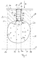
- Fig. 1 is a cross section through a generally designated 10 according to the invention Trench arrangement shown.
- the cutting plane is included placed so that they in the direction of gravity indicated by the arrow g runs.
- Fig. 1 shows a sealed bottom 12, which at its bottom top 12a is walkable and passable.
- the sealed bottom 12 may be, for example be a paved parking lot.
- a Manhole cover 14 for covering a circular cylindrical shaft 16 intended.
- the longitudinal axis 18 of the cylindrical shaft 16 extends in Gravity action direction g and lies in the above-mentioned Cutting plane.
- the cylindrical shaft 16 leads to an underground trench 20, which has a sphere-like shape. With this rather atypical spherical shape is to be shown that the inventive Arrangement of a shaft with respect to a trench generally valid and is applicable.
- the rig 20 is heaped up with a loose bed of gravel 22. Of the Gravel 22 is indicated by the circles drawn in the trench volume. The envelope of the gravel filling marks the rig wall 20a.
- the shaft 16 and the rigging 20 are surrounded by soil 24.
- the soil 24 is indicated by punctuation.
- the shaft 16 is made of simple circular cylindrical Schacht hypolligenn 26th constructed, which are stacked in the direction of the shaft longitudinal axis 18.
- each shaft filling body 26 is viewed on its upper side 26a a laid in the soil 24 state with a circumferential Provided projection 26b.
- each shaft filler 26 is at his Bottom 26c when viewing a laid in the soil 24 state with a circumferential recess 26 d provided, with which in the stacked State, a projection 26b of an adjacent Schacht hypochll stressess engaged is.
- the outer envelope of the circular cylindrical shell of the shaft 16b defines the shaft wall 16a.
- the shaft filler has one of the Upper side 26a to the bottom 26c reaching side wall 26e.
- the manhole cover 14 which may be about a manhole cover, can Rainwater from the bottom surface 12a enter the shaft 16, flow through it and get into the trench 20. There is the water cached and slowly by infiltration to the soil 24 issued. Through the shaft 16 is the trench, about to review their Condition or for repair work, achievable.
- the advantage of the present invention is that for the formation of the Schachtes 16 no additional excavation is necessary.
- To form the trench assembly must be the volume of the trench 20 and in the direction of gravity g overlying soil 24 in the hatched area A to be dug.
- the surface orthogonal to the direction of gravity g of the excavated area A of the soil 24 is determined by a projection of the trench 20 in the direction of the direction of gravity g in a direction of gravity g direction orthogonal plane E.
- the Level E is orthogonal to the drawing plane of FIG. 1.
- the shaft is arranged such that of the shaft wall 16a cut-out portion 20a1 of the rigging wall 20a and a Berntonline 20a2 a contact of shaft wall 16a and Rigolenwandung 20a is arranged such that a projection of the contact line 20a2 and the cut out Rigolenwandungs Scheme 20a1 in the direction of gravity g in the direction of gravity g direction orthogonal Plane E within a projection of the trench 20 in the direction of gravity action g lies in this plane.
- the projection of the trench 20 into the plane E is in Fig. 1 denotes 28, the projection of the shaft wall 16a cut out Rigolenwandungs Schemes 20a1 is designated in Fig. 1 at 30.
- the edge line 28a of the projection 28 of the trench 20 surrounds the Line 30a of the projection of the contact line 20a2. This will ensure that even if the shaft 16 is not in the direction of gravity g, but at an angle, at least one significant section of the shaft 16 through the Erdaushub Scheme A through would, so that little or no additional excavation for the Shaft 16 are necessary. Furthermore, this arrangement of the Schacht 16 a seal of the shaft entrance into the trench 20 simplified.
- the seal may even be dispensable under certain circumstances, if, as in in Fig. 1 example, the cut out Rigolenwandungsabêt 20a1 in an upper area, preferably at the highest geodetic point, the rigging 20 is provided, as stored in the trench 20 of water from bottom up and thus the shaft entrance area only very late and achieved only in rare cases.
- Figs. 2 and 3 is a preferred embodiment of an inventive Rigolean extract and Schacht hypolligenn invention shown schematically.
- Fig. 2 shows a cross section through the Trench arrangement and the surrounding earth area along one in Fig. 3rd indicated level II-II.
- Figure 3 shows a longitudinal section through the Trench arrangement along the indicated in Fig. 2 level III-III.
- FIG. 2 is a cuboid Rigole 120 shown by stacked Rigolen hypollianu 132 in the Supported substantially the same corresponding dimensions.
- the lowest Location of Rigolen hypollianun is on the arrangement level R, one Bowing plane to the Rigolenboden 120b, arranged.
- the arrangement level In the example shown, R is orthogonal to the direction of gravity action oriented.
- the Rigolen hypollianu 132 have a length I, a height h and a width b (see Fig. 3).
- the Rigole 120 is in in the example shown in FIGS. 2 and 3 completely of soil 124th surround. But you can also with the Rigolenboden 120b on a Restrained gravel bed. Again, the envelope determines the packing 132 is the rig wall 120a.
- a Liquid line 136 functional elements are provided, namely a Liquid line 136, a combined pump and filter unit 138 and a level gauge 140.
- the lowermost hopper filling body 127 has a curved cable outlet 136b, from which liquid into one of the lowest Schacht Schicht Canaleck stresses 127 formed pump sump 129 enters or from this is discharged via the pump and filter unit 138.
- the fluid meter 140 may be, for example, a pressure gauge be, which via lines not shown, the result of a pressure measurement provides to the soil surface, from which a water level in the Rigole 120 can be calculated.
- the line sections 136a can be firmly connected to the shaft filling body or even integrally formed with this, such as when the shaft filling body is produced in the plastic injection molding process.
- standardized at the manhole fillers Attachment points with appropriate attachment points Matching functional elements to be provided, in particular at in the plastic injection molding produced Schachthell stressesn to it Functional elements, such as the pump and filter unit 138, a pump alone, a filter unit alone or the measuring device 140 in a simpler To attach way.
- the trench 120 can be reached via the shaft 116, so that by the shaft 116 cleaning or / and inspection means, such as cleaning lances, Camera robots into which the Rigole can be introduced. at a man can also manhole 116 sufficiently large dimensions descend to the Rigole 120.
- the projection corresponds to the Rigole 120 in the direction of gravity g direction orthogonal plane E the plan of the Rigole 120.
- the outer contour of the projection of the Rigole 120 is designated 128a.
- the entrance to the shaft is in the trench 120 advantageously at the top of the rigging 120, i. around Rigolde blanket 120c.
- For the shaft 116 is no additional excavation necessary.
- works to seal the rigging 120 compared with trench arrangements with shaft and trench of the prior art Technology greatly simplified.
- Dashed line a second shaft 150 is indicated, which in addition to the shaft 116 in the other longitudinal end region of the trench 120th can be provided to ensure that every point in the trench can be reached by a shaft.
- the contact line of the shaft wall 150a of the duct 150 with the rig wall 120a is 150a2 designated.
- the wells 116 and 150 are substantially one another parallel.
- the shaft 150 may correspond to the shaft 116 be constructed.
- a projection of the shaft in Gravity action direction be included, such that a part of the Projection of the contact line in the direction of gravity with the edge of the Projection of the rigging coincides.
Landscapes
- Engineering & Computer Science (AREA)
- Health & Medical Sciences (AREA)
- Life Sciences & Earth Sciences (AREA)
- Hydrology & Water Resources (AREA)
- Public Health (AREA)
- Water Supply & Treatment (AREA)
- Environmental & Geological Engineering (AREA)
- Sewage (AREA)
- Devices For Use In Laboratory Experiments (AREA)
- Underground Structures, Protecting, Testing And Restoring Foundations (AREA)
Priority Applications (2)
| Application Number | Priority Date | Filing Date | Title |
|---|---|---|---|
| DE202004021642U DE202004021642U1 (de) | 2003-10-15 | 2004-09-01 | Rigolenanordnung mit Rigole und Schacht |
| PL04020806T PL1526223T3 (pl) | 2003-10-15 | 2004-09-01 | Układ kanału odwadniającego z kanałem odwadniającym i studzienką |
Applications Claiming Priority (2)
| Application Number | Priority Date | Filing Date | Title |
|---|---|---|---|
| DE10348024A DE10348024A1 (de) | 2003-10-15 | 2003-10-15 | Rigolenanordnung mit Rigole und Schacht |
| DE10348024 | 2003-10-15 |
Publications (3)
| Publication Number | Publication Date |
|---|---|
| EP1526223A2 true EP1526223A2 (fr) | 2005-04-27 |
| EP1526223A3 EP1526223A3 (fr) | 2007-08-29 |
| EP1526223B1 EP1526223B1 (fr) | 2011-08-17 |
Family
ID=34384372
Family Applications (1)
| Application Number | Title | Priority Date | Filing Date |
|---|---|---|---|
| EP04020806A Expired - Lifetime EP1526223B1 (fr) | 2003-10-15 | 2004-09-01 | Dispositif d'infiltration avec chambre d'infiltration et regard |
Country Status (5)
| Country | Link |
|---|---|
| EP (1) | EP1526223B1 (fr) |
| AT (1) | ATE520833T1 (fr) |
| DE (3) | DE10348024A1 (fr) |
| ES (1) | ES2368714T3 (fr) |
| PL (1) | PL1526223T3 (fr) |
Cited By (5)
| Publication number | Priority date | Publication date | Assignee | Title |
|---|---|---|---|---|
| EP2065523A3 (fr) * | 2007-11-30 | 2009-06-17 | Michael Heitker | Rigole destinée au stockage et/ou à l'infiltration d'eau de surface |
| EP2148016A1 (fr) | 2008-07-25 | 2010-01-27 | Ralph-Peter Dr.-Ing. Hegler | Agencement de rigoles |
| DE202011050862U1 (de) * | 2011-07-29 | 2012-11-15 | Rehau Ag + Co | Unterirdische Wasserspeicher- und Wasserversickervorrichtung |
| EP2099977A4 (fr) * | 2006-12-06 | 2015-02-25 | Jack Mckenzie Droomer | Structure de soutien |
| WO2019215238A1 (fr) | 2018-05-11 | 2019-11-14 | ACO Severin Ahlmann GmbH & Co Kommanditgesellschaft | Unité de rigole de corps de remplissage, système de rigole de corps de remplissage et éléments de regard |
Families Citing this family (3)
| Publication number | Priority date | Publication date | Assignee | Title |
|---|---|---|---|---|
| DE102010053374A1 (de) * | 2010-12-03 | 2012-06-06 | Rehau Ag + Co. | Verfahren zur Herstellung einer Rigole |
| DE102014222520A1 (de) | 2014-11-04 | 2016-05-04 | Fränkische Rohrwerke Gebr. Kirchner Gmbh & Co. Kg | Wirbeldrosselvorrichtung |
| DE202018104583U1 (de) * | 2018-08-09 | 2019-11-22 | Rehau Ag + Co | Halteelement |
Citations (3)
| Publication number | Priority date | Publication date | Assignee | Title |
|---|---|---|---|---|
| WO2000040811A1 (fr) | 1999-01-05 | 2000-07-13 | THEELEN, Jörg | Conduite d'eau |
| WO2001029334A1 (fr) | 1999-10-18 | 2001-04-26 | Humberto Urriola | Canaux de drainage modulaires |
| US6626609B1 (en) | 1999-10-21 | 2003-09-30 | Eco-Plan 21 Co., Ltd. | Water storing block and connecting member for water storing block and rain water storing/infiltrating structure |
Family Cites Families (8)
| Publication number | Priority date | Publication date | Assignee | Title |
|---|---|---|---|---|
| JPH09296486A (ja) * | 1996-04-30 | 1997-11-18 | Takiron Co Ltd | 地下貯水槽 |
| DE29620170U1 (de) * | 1996-11-20 | 1997-01-23 | Intewa Ingenieur-Gesellschaft für Energie- und Wassertechnik mbH, 52070 Aachen | Konstruktion einer Versickerungsanlage |
| DE29923191U1 (de) * | 1999-12-11 | 2000-07-13 | Ingenieurgesellschaft Prof. Dr. Sieker mbH, 15366 Dahlwitz-Hoppegarten | Naturnahes Straßenentwässerungssystem |
| US6719490B2 (en) * | 2001-04-18 | 2004-04-13 | Robert M. Maestro | Stormwater receiving assembly |
| DE10123754A1 (de) | 2001-05-16 | 2002-12-05 | Kirchner Fraenk Rohr | Rigolenanordnung sowie Rigolenbauteil zu dessen Aufbau |
| DE20119076U1 (de) * | 2001-11-23 | 2002-04-04 | 2H Kunststoff GmbH, 48493 Wettringen | Wasserspeicherelement für den Erdeinbau |
| DE60323586D1 (de) * | 2002-10-31 | 2008-10-30 | Polypipe Civils Ltd | Grundwasserdrainagesystem |
| DE20303343U1 (de) * | 2003-03-01 | 2003-06-12 | Hauraton Betonwarenfabrik GmbH & Co. KG, 76437 Rastatt | Versickerungssystem |
-
2003
- 2003-10-15 DE DE10348024A patent/DE10348024A1/de not_active Withdrawn
-
2004
- 2004-09-01 DE DE202004021642U patent/DE202004021642U1/de not_active Expired - Lifetime
- 2004-09-01 AT AT04020806T patent/ATE520833T1/de active
- 2004-09-01 PL PL04020806T patent/PL1526223T3/pl unknown
- 2004-09-01 EP EP04020806A patent/EP1526223B1/fr not_active Expired - Lifetime
- 2004-09-01 DE DE202004021837U patent/DE202004021837U1/de not_active Expired - Lifetime
- 2004-09-01 ES ES04020806T patent/ES2368714T3/es not_active Expired - Lifetime
Patent Citations (3)
| Publication number | Priority date | Publication date | Assignee | Title |
|---|---|---|---|---|
| WO2000040811A1 (fr) | 1999-01-05 | 2000-07-13 | THEELEN, Jörg | Conduite d'eau |
| WO2001029334A1 (fr) | 1999-10-18 | 2001-04-26 | Humberto Urriola | Canaux de drainage modulaires |
| US6626609B1 (en) | 1999-10-21 | 2003-09-30 | Eco-Plan 21 Co., Ltd. | Water storing block and connecting member for water storing block and rain water storing/infiltrating structure |
Cited By (7)
| Publication number | Priority date | Publication date | Assignee | Title |
|---|---|---|---|---|
| EP2099977A4 (fr) * | 2006-12-06 | 2015-02-25 | Jack Mckenzie Droomer | Structure de soutien |
| EP2065523A3 (fr) * | 2007-11-30 | 2009-06-17 | Michael Heitker | Rigole destinée au stockage et/ou à l'infiltration d'eau de surface |
| WO2009068019A3 (fr) * | 2007-11-30 | 2009-08-20 | Michael Heitker | Fosse pour stocker et/ou absorber/retenir de l'eau de surface |
| EP2148016A1 (fr) | 2008-07-25 | 2010-01-27 | Ralph-Peter Dr.-Ing. Hegler | Agencement de rigoles |
| DE202011050862U1 (de) * | 2011-07-29 | 2012-11-15 | Rehau Ag + Co | Unterirdische Wasserspeicher- und Wasserversickervorrichtung |
| WO2019215238A1 (fr) | 2018-05-11 | 2019-11-14 | ACO Severin Ahlmann GmbH & Co Kommanditgesellschaft | Unité de rigole de corps de remplissage, système de rigole de corps de remplissage et éléments de regard |
| DE102018111300A1 (de) * | 2018-05-11 | 2019-11-14 | ACO Severin Ahlmann GmbH & Co Kommanditgesellschaft | Füllkörperrigoleneinheit, Füllkörperrigolensystem und Schachtelement |
Also Published As
| Publication number | Publication date |
|---|---|
| DE202004021642U1 (de) | 2009-09-10 |
| PL1526223T3 (pl) | 2012-01-31 |
| EP1526223A3 (fr) | 2007-08-29 |
| DE202004021837U1 (de) | 2011-09-08 |
| DE10348024A1 (de) | 2005-05-19 |
| ATE520833T1 (de) | 2011-09-15 |
| ES2368714T3 (es) | 2011-11-21 |
| EP1526223B1 (fr) | 2011-08-17 |
Similar Documents
| Publication | Publication Date | Title |
|---|---|---|
| DE10123754A1 (de) | Rigolenanordnung sowie Rigolenbauteil zu dessen Aufbau | |
| EP1526223B1 (fr) | Dispositif d'infiltration avec chambre d'infiltration et regard | |
| AT391506B (de) | Vorrichtung zur abfuehrung von waerme in den erdboden bzw. zur aufnahme der waerme aus dem erdboden | |
| DE202004018319U1 (de) | Sicker- und Drainagekörper aus einzelnen Systemelementen | |
| DE19705824A1 (de) | Element zum Versickern einer Flüssigkeit | |
| DE10201347C5 (de) | Einlaufvorrichtung für die Abführung von Regenwasser von einem Dach | |
| DE2415023C3 (de) | Lärmschutzwall | |
| DE202004005768U1 (de) | Bauteil bzw. Bauwerk zur Leitung von Wasser, das im Gerinne mit einer Wärmerückgewinnung ausgestattet werden kann | |
| DE102011111127B4 (de) | Hochwasser-Schutzsystem | |
| DE202018102880U1 (de) | Schott für den Hochwasserschutz und Durchgang mit einem solchen Schott | |
| EP4230839B1 (fr) | Construction de tunnel | |
| EP1731682B1 (fr) | Système de canalisation à cascade pour eaux de surface | |
| EP4706380A2 (fr) | Puits pour la régulation de l'eau souterraine | |
| AT513567A1 (de) | Gerinne zur Abfuhr von Oberflächenwässern | |
| EP3470577A1 (fr) | Dispositif de bloquage de voie contre des véhicules | |
| EP2844805B1 (fr) | Partie inférieure de boîte | |
| AT513278B1 (de) | Gerinne zur Abfuhr von Oberflächenwässern | |
| EP3369862B1 (fr) | Élément de chéneau destiné à former un canal d'écoulement des eaux | |
| EP2426264B1 (fr) | Boîtier | |
| EP3107166B1 (fr) | Passage de cable permettant de faire passer une conduite dans un element de sol ou de paroi | |
| DE20204171U1 (de) | Wasserspeicherelement für den Erdeinbau | |
| AT523605B1 (de) | Wärmedämmendes Tiefbauwerk und Verfahren zu dessen Herstellung | |
| DE202011104877U1 (de) | Entwässerungs-Rinnensystem | |
| EP1528168A2 (fr) | Rigole pour stockage intermédiaire de liquide, en particulier l'eau de pluie | |
| DE20105694U1 (de) | Wasserspeicher- und -rückhaltesystem |
Legal Events
| Date | Code | Title | Description |
|---|---|---|---|
| PUAI | Public reference made under article 153(3) epc to a published international application that has entered the european phase |
Free format text: ORIGINAL CODE: 0009012 |
|
| AK | Designated contracting states |
Kind code of ref document: A2 Designated state(s): AT BE BG CH CY CZ DE DK EE ES FI FR GB GR HU IE IT LI LU MC NL PL PT RO SE SI SK TR |
|
| AX | Request for extension of the european patent |
Extension state: AL HR LT LV MK |
|
| PUAL | Search report despatched |
Free format text: ORIGINAL CODE: 0009013 |
|
| AK | Designated contracting states |
Kind code of ref document: A3 Designated state(s): AT BE BG CH CY CZ DE DK EE ES FI FR GB GR HU IE IT LI LU MC NL PL PT RO SE SI SK TR |
|
| AX | Request for extension of the european patent |
Extension state: AL HR LT LV MK |
|
| 17P | Request for examination filed |
Effective date: 20071128 |
|
| AKX | Designation fees paid |
Designated state(s): AT BE BG CH CY CZ DE DK EE ES FI FR GB GR HU IE IT LI LU MC NL PL PT RO SE SI SK TR |
|
| 17Q | First examination report despatched |
Effective date: 20090723 |
|
| GRAP | Despatch of communication of intention to grant a patent |
Free format text: ORIGINAL CODE: EPIDOSNIGR1 |
|
| GRAS | Grant fee paid |
Free format text: ORIGINAL CODE: EPIDOSNIGR3 |
|
| RIN1 | Information on inventor provided before grant (corrected) |
Inventor name: KRIESE, JENS Inventor name: ADAMS, DIETMAR |
|
| RTI1 | Title (correction) |
Free format text: LEACHING CHAMBER DEVICE WITH LEACHING CHAMBER AND MANHOLE |
|
| GRAA | (expected) grant |
Free format text: ORIGINAL CODE: 0009210 |
|
| AK | Designated contracting states |
Kind code of ref document: B1 Designated state(s): AT BE BG CH CY CZ DE DK EE ES FI FR GB GR HU IE IT LI LU MC NL PL PT RO SE SI SK TR |
|
| REG | Reference to a national code |
Ref country code: GB Ref legal event code: FG4D Free format text: NOT ENGLISH |
|
| REG | Reference to a national code |
Ref country code: CH Ref legal event code: EP |
|
| REG | Reference to a national code |
Ref country code: IE Ref legal event code: FG4D Free format text: LANGUAGE OF EP DOCUMENT: GERMAN |
|
| REG | Reference to a national code |
Ref country code: DE Ref legal event code: R096 Ref document number: 502004012793 Country of ref document: DE Effective date: 20111013 |
|
| REG | Reference to a national code |
Ref country code: ES Ref legal event code: FG2A Ref document number: 2368714 Country of ref document: ES Kind code of ref document: T3 Effective date: 20111121 |
|
| REG | Reference to a national code |
Ref country code: NL Ref legal event code: T3 |
|
| REG | Reference to a national code |
Ref country code: SE Ref legal event code: TRGR |
|
| PG25 | Lapsed in a contracting state [announced via postgrant information from national office to epo] |
Ref country code: FI Free format text: LAPSE BECAUSE OF FAILURE TO SUBMIT A TRANSLATION OF THE DESCRIPTION OR TO PAY THE FEE WITHIN THE PRESCRIBED TIME-LIMIT Effective date: 20110817 Ref country code: PT Free format text: LAPSE BECAUSE OF FAILURE TO SUBMIT A TRANSLATION OF THE DESCRIPTION OR TO PAY THE FEE WITHIN THE PRESCRIBED TIME-LIMIT Effective date: 20111219 |
|
| PGFP | Annual fee paid to national office [announced via postgrant information from national office to epo] |
Ref country code: CZ Payment date: 20110829 Year of fee payment: 8 |
|
| REG | Reference to a national code |
Ref country code: PL Ref legal event code: T3 |
|
| PG25 | Lapsed in a contracting state [announced via postgrant information from national office to epo] |
Ref country code: CY Free format text: LAPSE BECAUSE OF FAILURE TO SUBMIT A TRANSLATION OF THE DESCRIPTION OR TO PAY THE FEE WITHIN THE PRESCRIBED TIME-LIMIT Effective date: 20110817 Ref country code: GR Free format text: LAPSE BECAUSE OF FAILURE TO SUBMIT A TRANSLATION OF THE DESCRIPTION OR TO PAY THE FEE WITHIN THE PRESCRIBED TIME-LIMIT Effective date: 20111118 Ref country code: SI Free format text: LAPSE BECAUSE OF FAILURE TO SUBMIT A TRANSLATION OF THE DESCRIPTION OR TO PAY THE FEE WITHIN THE PRESCRIBED TIME-LIMIT Effective date: 20110817 |
|
| REG | Reference to a national code |
Ref country code: IE Ref legal event code: FD4D |
|
| BERE | Be: lapsed |
Owner name: FRANKISCHE ROHRWERKE GEBR. KIRCHNER G.M.B.H. & CO Effective date: 20110930 |
|
| PG25 | Lapsed in a contracting state [announced via postgrant information from national office to epo] |
Ref country code: IE Free format text: LAPSE BECAUSE OF FAILURE TO SUBMIT A TRANSLATION OF THE DESCRIPTION OR TO PAY THE FEE WITHIN THE PRESCRIBED TIME-LIMIT Effective date: 20110817 Ref country code: SK Free format text: LAPSE BECAUSE OF FAILURE TO SUBMIT A TRANSLATION OF THE DESCRIPTION OR TO PAY THE FEE WITHIN THE PRESCRIBED TIME-LIMIT Effective date: 20110817 Ref country code: MC Free format text: LAPSE BECAUSE OF NON-PAYMENT OF DUE FEES Effective date: 20110930 |
|
| REG | Reference to a national code |
Ref country code: CH Ref legal event code: PL |
|
| PG25 | Lapsed in a contracting state [announced via postgrant information from national office to epo] |
Ref country code: RO Free format text: LAPSE BECAUSE OF FAILURE TO SUBMIT A TRANSLATION OF THE DESCRIPTION OR TO PAY THE FEE WITHIN THE PRESCRIBED TIME-LIMIT Effective date: 20110817 Ref country code: EE Free format text: LAPSE BECAUSE OF FAILURE TO SUBMIT A TRANSLATION OF THE DESCRIPTION OR TO PAY THE FEE WITHIN THE PRESCRIBED TIME-LIMIT Effective date: 20110817 |
|
| PLBE | No opposition filed within time limit |
Free format text: ORIGINAL CODE: 0009261 |
|
| STAA | Information on the status of an ep patent application or granted ep patent |
Free format text: STATUS: NO OPPOSITION FILED WITHIN TIME LIMIT |
|
| PG25 | Lapsed in a contracting state [announced via postgrant information from national office to epo] |
Ref country code: BE Free format text: LAPSE BECAUSE OF NON-PAYMENT OF DUE FEES Effective date: 20110930 Ref country code: DK Free format text: LAPSE BECAUSE OF FAILURE TO SUBMIT A TRANSLATION OF THE DESCRIPTION OR TO PAY THE FEE WITHIN THE PRESCRIBED TIME-LIMIT Effective date: 20110817 |
|
| 26N | No opposition filed |
Effective date: 20120521 |
|
| PG25 | Lapsed in a contracting state [announced via postgrant information from national office to epo] |
Ref country code: LI Free format text: LAPSE BECAUSE OF NON-PAYMENT OF DUE FEES Effective date: 20110930 Ref country code: CH Free format text: LAPSE BECAUSE OF NON-PAYMENT OF DUE FEES Effective date: 20110930 |
|
| REG | Reference to a national code |
Ref country code: DE Ref legal event code: R097 Ref document number: 502004012793 Country of ref document: DE Effective date: 20120521 |
|
| PGFP | Annual fee paid to national office [announced via postgrant information from national office to epo] |
Ref country code: SE Payment date: 20120919 Year of fee payment: 9 |
|
| PGFP | Annual fee paid to national office [announced via postgrant information from national office to epo] |
Ref country code: TR Payment date: 20120829 Year of fee payment: 9 Ref country code: PL Payment date: 20120823 Year of fee payment: 9 |
|
| PGFP | Annual fee paid to national office [announced via postgrant information from national office to epo] |
Ref country code: ES Payment date: 20120926 Year of fee payment: 9 Ref country code: IT Payment date: 20120924 Year of fee payment: 9 |
|
| PGFP | Annual fee paid to national office [announced via postgrant information from national office to epo] |
Ref country code: NL Payment date: 20120920 Year of fee payment: 9 |
|
| PGFP | Annual fee paid to national office [announced via postgrant information from national office to epo] |
Ref country code: AT Payment date: 20120912 Year of fee payment: 9 |
|
| PG25 | Lapsed in a contracting state [announced via postgrant information from national office to epo] |
Ref country code: LU Free format text: LAPSE BECAUSE OF NON-PAYMENT OF DUE FEES Effective date: 20110901 |
|
| PG25 | Lapsed in a contracting state [announced via postgrant information from national office to epo] |
Ref country code: BG Free format text: LAPSE BECAUSE OF FAILURE TO SUBMIT A TRANSLATION OF THE DESCRIPTION OR TO PAY THE FEE WITHIN THE PRESCRIBED TIME-LIMIT Effective date: 20111117 |
|
| PG25 | Lapsed in a contracting state [announced via postgrant information from national office to epo] |
Ref country code: HU Free format text: LAPSE BECAUSE OF FAILURE TO SUBMIT A TRANSLATION OF THE DESCRIPTION OR TO PAY THE FEE WITHIN THE PRESCRIBED TIME-LIMIT Effective date: 20110817 |
|
| PGFP | Annual fee paid to national office [announced via postgrant information from national office to epo] |
Ref country code: DE Payment date: 20130715 Year of fee payment: 10 |
|
| PGFP | Annual fee paid to national office [announced via postgrant information from national office to epo] |
Ref country code: GB Payment date: 20130919 Year of fee payment: 10 Ref country code: FR Payment date: 20130919 Year of fee payment: 10 |
|
| REG | Reference to a national code |
Ref country code: NL Ref legal event code: V1 Effective date: 20140401 |
|
| REG | Reference to a national code |
Ref country code: SE Ref legal event code: EUG |
|
| PG25 | Lapsed in a contracting state [announced via postgrant information from national office to epo] |
Ref country code: CZ Free format text: LAPSE BECAUSE OF NON-PAYMENT OF DUE FEES Effective date: 20130901 Ref country code: SE Free format text: LAPSE BECAUSE OF NON-PAYMENT OF DUE FEES Effective date: 20130902 |
|
| REG | Reference to a national code |
Ref country code: AT Ref legal event code: MM01 Ref document number: 520833 Country of ref document: AT Kind code of ref document: T Effective date: 20130901 |
|
| PG25 | Lapsed in a contracting state [announced via postgrant information from national office to epo] |
Ref country code: IT Free format text: LAPSE BECAUSE OF NON-PAYMENT OF DUE FEES Effective date: 20130901 Ref country code: NL Free format text: LAPSE BECAUSE OF NON-PAYMENT OF DUE FEES Effective date: 20140401 Ref country code: AT Free format text: LAPSE BECAUSE OF NON-PAYMENT OF DUE FEES Effective date: 20130901 |
|
| PG25 | Lapsed in a contracting state [announced via postgrant information from national office to epo] |
Ref country code: PL Free format text: LAPSE BECAUSE OF NON-PAYMENT OF DUE FEES Effective date: 20130901 |
|
| REG | Reference to a national code |
Ref country code: PL Ref legal event code: LAPE |
|
| REG | Reference to a national code |
Ref country code: DE Ref legal event code: R119 Ref document number: 502004012793 Country of ref document: DE |
|
| REG | Reference to a national code |
Ref country code: ES Ref legal event code: FD2A Effective date: 20150429 |
|
| GBPC | Gb: european patent ceased through non-payment of renewal fee |
Effective date: 20140901 |
|
| REG | Reference to a national code |
Ref country code: FR Ref legal event code: ST Effective date: 20150529 |
|
| PG25 | Lapsed in a contracting state [announced via postgrant information from national office to epo] |
Ref country code: GB Free format text: LAPSE BECAUSE OF NON-PAYMENT OF DUE FEES Effective date: 20140901 Ref country code: DE Free format text: LAPSE BECAUSE OF NON-PAYMENT OF DUE FEES Effective date: 20150401 Ref country code: ES Free format text: LAPSE BECAUSE OF NON-PAYMENT OF DUE FEES Effective date: 20130902 |
|
| PG25 | Lapsed in a contracting state [announced via postgrant information from national office to epo] |
Ref country code: FR Free format text: LAPSE BECAUSE OF NON-PAYMENT OF DUE FEES Effective date: 20140930 |
|
| PG25 | Lapsed in a contracting state [announced via postgrant information from national office to epo] |
Ref country code: TR Free format text: LAPSE BECAUSE OF NON-PAYMENT OF DUE FEES Effective date: 20130901 |