EP1525937A2 - Foret, trepan et méthode pour leur alimentation en liquide de refroidissement - Google Patents
Foret, trepan et méthode pour leur alimentation en liquide de refroidissement Download PDFInfo
- Publication number
- EP1525937A2 EP1525937A2 EP04256186A EP04256186A EP1525937A2 EP 1525937 A2 EP1525937 A2 EP 1525937A2 EP 04256186 A EP04256186 A EP 04256186A EP 04256186 A EP04256186 A EP 04256186A EP 1525937 A2 EP1525937 A2 EP 1525937A2
- Authority
- EP
- European Patent Office
- Prior art keywords
- water
- shank
- cooling
- supplying
- passage
- Prior art date
- Legal status (The legal status is an assumption and is not a legal conclusion. Google has not performed a legal analysis and makes no representation as to the accuracy of the status listed.)
- Withdrawn
Links
Images




Classifications
-
- B—PERFORMING OPERATIONS; TRANSPORTING
- B23—MACHINE TOOLS; METAL-WORKING NOT OTHERWISE PROVIDED FOR
- B23Q—DETAILS, COMPONENTS, OR ACCESSORIES FOR MACHINE TOOLS, e.g. ARRANGEMENTS FOR COPYING OR CONTROLLING; MACHINE TOOLS IN GENERAL CHARACTERISED BY THE CONSTRUCTION OF PARTICULAR DETAILS OR COMPONENTS; COMBINATIONS OR ASSOCIATIONS OF METAL-WORKING MACHINES, NOT DIRECTED TO A PARTICULAR RESULT
- B23Q11/00—Accessories fitted to machine tools for keeping tools or parts of the machine in good working condition or for cooling work; Safety devices specially combined with or arranged in, or specially adapted for use in connection with, machine tools
- B23Q11/10—Arrangements for cooling or lubricating tools or work
-
- B—PERFORMING OPERATIONS; TRANSPORTING
- B23—MACHINE TOOLS; METAL-WORKING NOT OTHERWISE PROVIDED FOR
- B23B—TURNING; BORING
- B23B51/00—Tools for drilling machines
- B23B51/06—Drills with lubricating or cooling equipment
-
- B—PERFORMING OPERATIONS; TRANSPORTING
- B23—MACHINE TOOLS; METAL-WORKING NOT OTHERWISE PROVIDED FOR
- B23Q—DETAILS, COMPONENTS, OR ACCESSORIES FOR MACHINE TOOLS, e.g. ARRANGEMENTS FOR COPYING OR CONTROLLING; MACHINE TOOLS IN GENERAL CHARACTERISED BY THE CONSTRUCTION OF PARTICULAR DETAILS OR COMPONENTS; COMBINATIONS OR ASSOCIATIONS OF METAL-WORKING MACHINES, NOT DIRECTED TO A PARTICULAR RESULT
- B23Q11/00—Accessories fitted to machine tools for keeping tools or parts of the machine in good working condition or for cooling work; Safety devices specially combined with or arranged in, or specially adapted for use in connection with, machine tools
- B23Q11/10—Arrangements for cooling or lubricating tools or work
- B23Q11/1092—Arrangements for cooling or lubricating tools or work specially adapted for portable power-driven tools
-
- B—PERFORMING OPERATIONS; TRANSPORTING
- B28—WORKING CEMENT, CLAY, OR STONE
- B28D—WORKING STONE OR STONE-LIKE MATERIALS
- B28D1/00—Working stone or stone-like materials, e.g. brick, concrete or glass, not provided for elsewhere; Machines, devices, tools therefor
- B28D1/14—Working stone or stone-like materials, e.g. brick, concrete or glass, not provided for elsewhere; Machines, devices, tools therefor by boring or drilling
- B28D1/146—Tools therefor
-
- B—PERFORMING OPERATIONS; TRANSPORTING
- B23—MACHINE TOOLS; METAL-WORKING NOT OTHERWISE PROVIDED FOR
- B23B—TURNING; BORING
- B23B2226/00—Materials of tools or workpieces not comprising a metal
- B23B2226/75—Stone, rock or concrete
-
- Y—GENERAL TAGGING OF NEW TECHNOLOGICAL DEVELOPMENTS; GENERAL TAGGING OF CROSS-SECTIONAL TECHNOLOGIES SPANNING OVER SEVERAL SECTIONS OF THE IPC; TECHNICAL SUBJECTS COVERED BY FORMER USPC CROSS-REFERENCE ART COLLECTIONS [XRACs] AND DIGESTS
- Y02—TECHNOLOGIES OR APPLICATIONS FOR MITIGATION OR ADAPTATION AGAINST CLIMATE CHANGE
- Y02P—CLIMATE CHANGE MITIGATION TECHNOLOGIES IN THE PRODUCTION OR PROCESSING OF GOODS
- Y02P70/00—Climate change mitigation technologies in the production process for final industrial or consumer products
- Y02P70/10—Greenhouse gas [GHG] capture, material saving, heat recovery or other energy efficient measures, e.g. motor control, characterised by manufacturing processes, e.g. for rolling metal or metal working
-
- Y—GENERAL TAGGING OF NEW TECHNOLOGICAL DEVELOPMENTS; GENERAL TAGGING OF CROSS-SECTIONAL TECHNOLOGIES SPANNING OVER SEVERAL SECTIONS OF THE IPC; TECHNICAL SUBJECTS COVERED BY FORMER USPC CROSS-REFERENCE ART COLLECTIONS [XRACs] AND DIGESTS
- Y10—TECHNICAL SUBJECTS COVERED BY FORMER USPC
- Y10T—TECHNICAL SUBJECTS COVERED BY FORMER US CLASSIFICATION
- Y10T408/00—Cutting by use of rotating axially moving tool
- Y10T408/03—Processes
-
- Y—GENERAL TAGGING OF NEW TECHNOLOGICAL DEVELOPMENTS; GENERAL TAGGING OF CROSS-SECTIONAL TECHNOLOGIES SPANNING OVER SEVERAL SECTIONS OF THE IPC; TECHNICAL SUBJECTS COVERED BY FORMER USPC CROSS-REFERENCE ART COLLECTIONS [XRACs] AND DIGESTS
- Y10—TECHNICAL SUBJECTS COVERED BY FORMER USPC
- Y10T—TECHNICAL SUBJECTS COVERED BY FORMER US CLASSIFICATION
- Y10T408/00—Cutting by use of rotating axially moving tool
- Y10T408/44—Cutting by use of rotating axially moving tool with means to apply transient, fluent medium to work or product
Definitions
- the present invention relates to a non-core type bit that has a cutting tip and designed to bore small holes in concrete blocks, a non-core drill apparatus that comprises a non-core type bit of this type, and a method of supplying cooling water to the tip of the non-core drill apparatus.
- a non-core type bit is used as a drill bit that is used to bore small holes, such as anchor-bolt holes, in concrete blocks (workpieces) such as concrete walls, floor beds or ceiling panels.
- the non-core type bit can make holes, without leaving cores.
- a non-core drill apparatus comprises a non-core type bit.
- a non-core type bit includes a shaft-shaped shank and a cutting tip. The tip (diamond tip) is made of sintered diamond and secured to the distal end of the shank.
- cooling water is continuously supplied to the tip in order mainly to prevent a temperature rise of the tip.
- a system of supplying cooling water to the tip of a non-core type bit is disclosed in, for example, Japanese. Patent Application KOKAI Publication No. 11-10425.
- the shaft-shaped shank has a water passage for supplying cooling water. Through this passage, cooling water is supplied to the tip secured to the distal end of the shank.
- the cooling water supplied to the tip through the water passage made in the shank leaks generally via the space around the shank.
- the cooling water discharged is muddy, containing dust particles made as the tip cuts the concrete block.
- the muddy water makes the concrete block dirty, particularly at the part that lies around the hole. This is inevitably because the muddy water is discharged from the hole via the space around the shank.
- the cooling water is discharged through the space around the shank.
- the cooling water discharged falls directly onto the worker who is using the drill apparatus. This not only lowers the efficiency of boring holes, but also impairs the work safety.
- Japanese Patent Publication No. 3257602 discloses a non-core drill apparatus that has a dust-collecting means for collecting and processing the cooling water discharged from the hole being made, through the space around the shank.
- the dust-collecting means includes a suction head and a dust collector.
- the suction head covers that surface part of the concrete block, in which a hole is being bored.
- the dust collector draws the cooling water discharged into the suction head from the hole via the space around the shank.
- the cooling water is discharged from the hole through the space around the shank.
- the cooling water is thus wasted, not recycled to be used again. This raises the cost of boring the hole, particularly in the case where liquid dedicated to the cooling of the tip is used as cooling water.
- An object of the present invention is to provide a non-core type bit that can easily bore a hole in a concrete block, at a desired position, without making the block dirty.
- Another object of the present invention is to provide a non-core drill apparatus that can easily bore a hole in a concrete block, at a desired position, without making the block dirty.
- Still another object of the present invention is to provide a method of supplying cooling water to the tip of the non-core drill apparatus such that the cooling water may not make dirty the concrete block in which the apparatus is making a hole and may be recycled to be used again.
- a non-core type bit according to this invention which is described in claim 1, includes a water-discharging passage provided in a shank, along with a water-supplying passage.
- the cooling water can therefore be discharged through the water-discharging passage, without spilling around the hole being bored in a workpiece. This prevents the cooling water from making the workpiece dirty. Further, the hole can be seen since no suction heads cover the hole. This makes it possible to bore the hole at a desired position. Since a suction head need not be used, the hole boring can be achieved with high efficiency.
- Non-core type bits according to the invention which are described in claims 2 and 3, are simple in structure.
- a water-discharging passage is provided in the shank, along with a water-supplying passage.
- the cooling water can therefore be discharged through the water-discharging passage, without spilling around the hole being bored in a workpiece. This prevents the cooling water from making the workpiece dirty. Further, the hole can be seen since no suction heads cover the hole. This makes it possible to bore the hole at a desired position. Since a suction head need not be used, the hole boring can be achieved with high efficiency.
- the suction head need not be covered to discharge the cooling water, because the water can be supplied to the tip through the water-supplying passage and water-supplying port of the shank and discharged from the hole through the water-discharging port and water-discharging passage of the shank. This helps to simplify the structure of the non-core drill apparatus.
- a non-core drill apparatus which is described in claim 5, includes a discharging means, which has a water-recollecting tank.
- the water-recollecting tank stores the cooling water discharged from the hole being made in a workpiece. This prevents the cooling water from being drained out.
- the cooling-water source includes a water-supplying tank and a pump means.
- the water-supplying tank stores cooling water.
- the non-core drill apparatus can therefore bore holes, even in places where no water source is available.
- the cooling water supplied to the tip provided at the distal end of the shank can be discharged from the hole being bored in a workpiece through the water-discharging passage, without spilling around the hole.
- the cooling water discharged from the hole does not make the workpiece dirty.
- the hole can be seen because no suction head covers the hole. This makes it possible to bore the hole at a desired position. Since the suction head need not be used, the hole boring can be achieved with high efficiency.
- the cooling water can be recycled for re-use.
- the method can bore holes, even in places where no water source is available.
- the supply of cooling water is delayed by a predetermined time from the time when the drill main body starts operating. This prevents the cooling water from leaking to the workpiece or from spilling thereto, and ultimately a loss of the cooling water.
- FIG. 1 is a partially sectional view
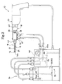
- FIG. 2 is a schematic representation of the apparatus 10.
- the non-core drill apparatus 10 comprises a non-core type bit 16 and a drill main body 20.
- the main body 20 is designed to rotate the non-core type bit 16.
- the bit 16 includes a shank 12 and a tip 14.
- the tip 14 is secured to the distal end of the shank 12.
- the drill main body 20 is similar to an electric tool of the known type, such as an electric drill.
- the main body 20 has a motor (not shown) and a rotary member 18.
- the rotary member 18 is driven by the motor.
- the tip 14 is made of, for example, sintered diamond. It has a diameter about 1 to 2 mm greater than that of the shank 12.
- the tip 14 includes two tip-strips.
- the tip-strips are spaced apart, defining a slit 27 between them.
- the front 14a of the tip 14, i.e., the cutting surface of the tip, is concave at the center.
- the slit 27 extending between the tip-strips functions as a passage, as will be described later.
- the non-core type bit 16 is coupled to the rotary member 18 of the drill main body 20. Hence, the bit 16 is rotated when the rotary member 18 is driven by the motor.
- a water-supplying passage 22 and a water-discharging passage 26 are made in the shank 12, both extending parallel to the axis of the shank 12.
- the passage 22 is provided to supply cooling water to the tip 14 fixed to the distal end of the shank 12.
- the passage 26 is provided to discharge the cooling water from the hole 24 which the tip 14 has bored.
- the water-supplying passage 22 has an opening 22a at the distal end, which communicates with the slit 27 of the tip 14.
- the water-discharging passage 26 has an opening 26a at the distal end, which communicates with the slit 27, too.
- the passages 22 and 26 open to the outside, at the openings 22a and 26a, respectively.
- the non-core type bit 16 is coupled by a swivel 32 to the drill main body 20.
- the swivel 32 includes a swivel main body 34 and a rotary member 36.
- the rotary member 36 is rotatably held in the swivel main body 34.
- the swivel 32 is arranged between the drill main body 20 and the non-core type bit 16.
- the swivel main body 34 is secured to the housing 40 of the drill main body 20 and cannot move.
- the rotary member 36 is coupled to the rotary member 18 of the drill main body 20 by a joint member 38 such as a drill chuck. The rotary member 36 is therefore rotated when the rotary member 18 is rotated.
- the rotary member 36 of the swivel 32 has a distal end part 36a that has a large diameter.
- the proximal end part 12a of the shank 12 is fitted in the distal end part 36a of the rotary member 36.
- the distal end part 36a has a rotation-preventing part 42.
- the shank 12 has a flange 12b, which has a rotation-preventing part 43.
- a joint ring 46 is set in engagement with the flange 12b of the shank 12 and has a female screw.
- the female screw meshes with the male screw made on the distal end part 36a of the rotary member 36, which has a large diameter.
- the main body 34 of the swivel 32 has a water-supplying port 28 and a water-discharging port 30.
- the ports 28 and 30 communicate with the water-supplying passage 22 and water-discharging passage 26 of the shank 12, respectively.
- the rotary member 36 of the swivel 32 has passages 50 and 51.
- the passage 50 connects the water-supplying passage 22 of the shank 12 to the water-supplying port 28 of the swivel main body 34.
- the passage 51 connects the water-discharging passage 26 of the shank 12 to the water-discharging port 30 of the swivel main body 34.
- water reservoirs 52 and 53 are provided between the swivel main body 34 and the rotary member 36.
- the water-supplying port 28 of the swivel main body 34 always communicates with the water-supplying passage 22 of the shank 12 through the water reservoir 52.
- the port 30 of the swivel main body 34 always communicates with the water-discharging passage 26 of the shank 12 through the water reservoir 53.
- the cooling water is supplied to the tip 14 through the water-supplying port 28 of the swivel 32 and the water-supplying passage 22 of the shank 12. And the cooling water is discharged from the hole 24 being bored by the tip 14, through the water-discharging passage 26 of the shank 12 and the water-discharging port 30 of the swivel 32.
- the non-core drill apparatus 10 further comprises a cooling-water source 54 and a cooling-water discharging means 56.
- the cooling-water source 54 and cooling-water discharging means 56 are connected to the water-supplying port 28 and water-discharging port 30 of the swivel 32, respectively.
- the cooling-water discharging means 56 has a water-recollecting tank 58 and a vacuum pump 60.
- the tank 58 is a sealed tank and connected to the water-discharging port 30 of the swivel 32 to collect the cooling water from the water-discharging passage 26 of the shank 12.
- the vacuum pump 60 generates a vacuum in the tank 58 (i.e., seated tank) so that a suction force may acts in the water-discharging port 30 of the swivel 32.
- the cooling-water source 54 has, for example, a water-supplying tank 62 and a pump means 64.
- the tank 62 stores cooling water and has a water-outlet port 64b.
- the pump means 64 supplies the cooling water from the water-supplying tank 62 to the outlet port 64b.
- the pump means 64 has a water-inlet port 64a, which is provided in the water-supplying tank 62.
- the water-outlet port 64b is connected to the water-supplying port 28 of the swivel 32.
- the water-supplying tank 62 of the cooling-water source 54 is a sealed tank.
- the tank 62 therefore serves as the water-recollecting tank 58 of the cooling-water discharging means 56, as well.
- the cooling water discharged from the hole 24 by the cooling-water discharging means 56 can be used repeatedly as cooling water to be supplied to the tip 14. In other words, the cooling water can be recycled and used again and again.
- the pump means 64 When the pump means 64 is operated, with a predetermined amount of water stored in the water-recollecting tank 58 (or water-supplying tank 62), the cooling water drawn into the tank 58 through the water-inlet port 64a flows to the water-supplying port 28 of the swivel 32 via the water-outlet port 64b. The cooling water then flows through the water-supplying passage 22 of the shank 12 to the opening 22a of the passage 22. The cooling water is thus applied from the opening 22a to the tip 14 (see FIGS. 1 and 3).
- the vacuum pressure generated in the water-recollecting tank 58 (or water-supplying tank 62) as the vacuum pump 60 operates acts in a water-discharging port 65 that communicates with the water-discharging port 30 of the swivel 32. A suction force is thereby generated in the port 65.
- the cooling water discharged from the hole 24 is collected and stored in the water-recollecting tank 58 through the water-discharging passage 26 of the shank 12 and the water-discharging port 30 of the swivel 32.
- the water-supplying passage 22 and water-discharging passage 26 are provided in the shank 12 in the present invention.
- the cooling water supplied via the water-supplying passage 22 is therefore discharged through the water-discharging passage 26, without leaking through the space around the shank 12.
- the suction force generated by the cooling-water discharging means 56 expels the cooling water from the hole 24 via the water-discharging passage 26 and the water-discharging port 30 of the swivel 32.
- the water would not leak through the space about the shank 12.
- the water thus discharged from the hole 24 can easily be collected in the water-recollecting tank 58.
- the water thus collected can be supplied to the tip 14.
- the cooling water is used again to cool the tip 14. This minimizes the absolute use amount of cooling water.
- the non-core drill apparatus 10 can bore holes, without a loss of cooling water.
- the muddy water containing dust particles formed as the tip 14 bores a hole does not leak into the space around the shank 12.
- the muddy water does not make dirty the concrete block in which the hole is being bored.
- the block need not be cleaned at all. Therefore, apparatus 10 can bore holes in the block at high efficiency.
- the water-supplying passage 22 and water-discharging passage 26 are connected at their respective openings 22a and 26a to the slit 27 of the tip 14. Therefore, the cooling water flows into the hole 24 cut by the tip 14 through the water-supplying passage 22 and slit 27 and flows from the hole 24 through the slit 27 and water-discharging passage 26. As the cooling water flows through the slit 27, it contacts the tip 14, cooling the tip 14 efficiently. Since the water flows through the slit 27, it can be collected well from the very start of the hole-boring process and can be discharged well from the hole 24.
- the non-core type bit 16 of this invention is coupled to the rotary member 18 of the drill main body 20 and can therefore be rotated when the rotary member 18 is driven.
- Two passages are made in the shank 12 and extend parallel to the axis thereof.
- One passage is the water-supplying passage 22 that supplies the cooling water to the tip 14 provided at the distal end of the shank 12.
- the other passage is the water-discharging passage 26 that discharges the water from the hole 24 being bored by the tip 14.
- the tip 14 has the slit 27 that communicates with the water-supplying passage 22 and the water-discharging passage 26, both provided in the shank 12.
- cooling-water discharging means 56 connected to the water-discharging port 30 of the swivel 32 can draw the cooling water from the hole 24.
- a simple mechanism can discharge the cooling water from the hole 24.
- the cooling-water source 54 has the water-supplying tank 62 and the pump mans 64. Nonetheless, the cooling-water source 54 may not be used. Instead, a tap-water faucet may be connected directly to the water-supplying port 28 of the swivel 32, because it only needs to supply cooling water to the tip 14 that is provided at the distal end of the shank 12.
- the cooling-water source 54 that has the water-supplying tank 62 and the pump mans 64.
- the non-core drill apparatus 10 can be used anywhere, even if no tap-water faucets are available.
- the cooling-water discharging means 56 has the water-recollecting tank 58. Nonetheless, the means 56 may not have the water-recollecting tank 58.
- the cooling water may be discharged from the hole 24 directly into the drainage ditch, without storing the cooling water in a reservoir such as a water-recollecting tank.
- the non-core drill apparatus 10 can be used anywhere, even if no drainage ditches are provided.
- the water-recollecting tank 58 may have the cooling-water discharging means 56, and the water-supplying tank 62 may have the cooling-water source 54. In this case, the cooling water is recollected and stored in the tank 58 to be used again.
- the non-core drill apparatus 10 can bore holes anywhere, even if neither a tap-water faucet nor a drainage ditch is available. The apparatus 10 can therefore be a versatile one.
- the water-recollecting tank 58 and water-supplying tank 62 can be replaced by a single tank that has the cooling-water discharging means 56 and the cooling-water source 54. In this case, the cooling water can be recycled for repeated use. This minimizes the absolute amount of water necessary and the loss of water. The running cost of the non-core drill apparatus 10 therefore decreases, particularly when the cooling water is liquid dedicated to the cooling of the tip 14.
- the cooling-water discharging means 56 includes the water-recollecting tank 58 and the vacuum pump 60.
- the tank 58 is a sealed tank, and the vacuum pump 60 generates a vacuum in the tank 58.
- the cooling-water discharging means 56 may be replaced by a water-discharging means of the known type, which includes a storage tank and a suction pump. This is because it suffices to recollect the cooling water from the hole 24 into the water-recollecting tank 58 through the water-discharging passage 26, provided in the shank 12 and the water-discharging port 30 of the swivel 32.
- the cooling water discharged from the hole 24 and recollected in the water-recollecting tank 58 is muddy, containing the dust particles that are made as the tip 14 cuts the concrete block. If the muddy water is used as cooling water, the dust particles may clog the narrow passages in the pump means 64, the water-supplying passage 22 and water-discharging passage 26 of the shank 12.
- the water-supplying port 64a of the pump means 64 is located at so high a level that the pump means 64 supplies only the upper part of the water in the water-recollecting tank 58, to the water-supplying passage 22 made in the shank 12.
- the upper part of the water is clean, containing no dust particles that are deposited on the bottom of the water-recollecting tank 58. Since no filters are used, the apparatus 10 is simple in structure and, hence, can easily be maintained in good conditions.
- the non-core drill apparatus 10 bores the hole 24 in a flat concrete block. It is therefore difficult to recollect the cooling water until the hole 24 has some depth if the water is supplied to the tip 14 from the very beginning of the hole-boring work. Until the hole become sufficiently deep, the water is drained and wasted.
- the apparatus 10 has a control means 66 as is illustrated in FIGS. 1 and 2.
- the control means 66 controls the cooling-water source 54 so that the supply of cooling water is delayed by a prescribed time from the start of operation of the drill main body 20, i.e., namely from the time the rotary member 18 starts rotating.
- the control means 66 has a timer or the like that sets the time by which the supply of cooling water is delayed, if the cooling-water source 54 includes one water-supplying tank 62 (serving as water-recollecting tank 58, too) and the pump means 64.
- the cooling water may be intermittently supplied to the tip 14.
- the intermittent supply of cooling water helps to save the cooling water, as does the delayed supply of cooling water which prevents the draining of water at the start of operation of the drill main body 20.
- the absolute amount of cooling water required is small.
- the intermittent supply of cooling water may be performed after the hole 24 has acquired some depth. In this case, too, the absolute amount of cooling water is small.
- the shank 12 of the non-core type bit 16 is coupled to the rotary member 36 of the swivel 32 by the joint ring 46 that is a screw-type one.
- the shank 12 needs only to be coupled to the rotary member 36 of the swivel 32 so that it may rotate together with the rotary member 18 of the drill main body 20.
- the shank 12 can be coupled by any other means than the screw-type joint ring 46.
- the rotary member 18 of the drill main body 20 needs only to be coupled to the rotary member 36 of the swivel 32 so that it may rotate together with the rotary member 36.
- the rotary member 18 can be coupled by any other means than the drill chuck (i.e., joint member 38).
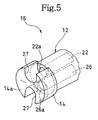
- the tip 14 has its shape defined by two substantially sector-shaped tip-strips in the first embodiment. It suffices for the tip 14 to have the slit 27 that communicates with the openings 22a and 26a of the water-supplying and water-discharging passages 22 and 26 that are made in the shank 12. Hence, the tip 14 can be made of a single tip-strip that has two slits 27 as is illustrated in FIG. 5.
- the openings 22a and 26a are made in the distal end of the water-supplying and water-discharging passages 22 and 26, respectively.
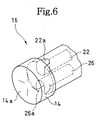
- the openings 22a and 26a need only to connect the passages 22 and 26 to the hole 24. Therefore, the openings 22a and 26a need not be made in the distal end of the shank 12. They can be made, for example, in the circumferential surface of the distal end of the shank 12 as is shown in FIG. 6.
- the tip 14 need not have a slit that communicates with the openings 22a and 26a of the shank 12. Since the tip 14 need not have a slit in its circumferential surface, it can be the ordinary type that is shown in FIG. 6.
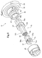
- the water-supplying passage 22 and the water-discharging passage 26 are cut in the shank 12, extending parallel to the axis of the shank 12. Nonetheless, the passages 22 and 26 may be coaxial, defined by an inner tube 68 and an outer tube 70 that are arranged coaxial as shown in FIG. 7 and 8.
- FIG. 7 and 8 show a non-core drill apparatus 10 according to the second embodiment of the invention.
- the inner tube 68 and the outer tube 70 constitute a shank 112.
- the inner space of the inner tube 68 serves as water-supplying passage 22, and the gap between the inner tube 68 and the outer tube 70 serves as water-discharging passage 26.
- the water-supplying passage 22 communicates with the water-supplying port 28 of the swivel 32, and the water-discharging passage 26 communicates with the water-discharging port 30 of the swivel 32.
- the passages 50 and 52 are thereby provided in the rotary member 36 of the swivel 32.
- the second embodiment is identical to the first embodiment, except for the shank 112. Therefore, the components identical to those of the first embodiment are designated at the same reference numerals and will not be described.
- the shank has a water-supplying passage 22 and a water-discharging passage 26.
- the cooling-water discharging means 56 can discharge and recollect the cooling water, by applying a suction force on the water, in the same manner as in the first embodiment.
- the inner space of the inner tube 68 serves as water-supplying passage 22, and the gap between the inner tube 68 and the outer tube 70 serves as water-discharging passage 26.
- the tubes 68 and 70 may define these passages, the other way around, nevertheless. That is, the inner space of the inner tube 68 may serve as water-discharging passage 26, and the gap between the inner tube 68 and the outer tube 70 may work as water- supplying passage 22.
Landscapes
- Engineering & Computer Science (AREA)
- Mechanical Engineering (AREA)
- Mining & Mineral Resources (AREA)
- Processing Of Stones Or Stones Resemblance Materials (AREA)
- Auxiliary Devices For Machine Tools (AREA)
- Drilling Tools (AREA)
Applications Claiming Priority (4)
| Application Number | Priority Date | Filing Date | Title |
|---|---|---|---|
| JP2003362721 | 2003-10-23 | ||
| JP2003362721 | 2003-10-23 | ||
| JP2004018328 | 2004-01-27 | ||
| JP2004018328A JP2005145041A (ja) | 2003-10-23 | 2004-01-27 | ノンコアタイプビット、ノンコアドリル装置およびその冷却水給排水方法 |
Publications (2)
| Publication Number | Publication Date |
|---|---|
| EP1525937A2 true EP1525937A2 (fr) | 2005-04-27 |
| EP1525937A3 EP1525937A3 (fr) | 2006-04-12 |
Family
ID=34395675
Family Applications (1)
| Application Number | Title | Priority Date | Filing Date |
|---|---|---|---|
| EP04256186A Withdrawn EP1525937A3 (fr) | 2003-10-23 | 2004-10-06 | Foret, trepan et méthode pour leur alimentation en liquide de refroidissement |
Country Status (3)
| Country | Link |
|---|---|
| US (1) | US20050105977A1 (fr) |
| EP (1) | EP1525937A3 (fr) |
| JP (1) | JP2005145041A (fr) |
Cited By (5)
| Publication number | Priority date | Publication date | Assignee | Title |
|---|---|---|---|---|
| CN101745833B (zh) * | 2008-12-16 | 2013-03-20 | 武汉重型机床集团有限公司 | 镗杆主轴带内冷自动拉刀结构 |
| EP2848340A1 (fr) * | 2013-09-13 | 2015-03-18 | Jakob Lach GmbH & Co. KG | Outil d'enlèvement de copeaux, en particulier outil de fraisage ou de forage |
| CN105710420A (zh) * | 2016-03-23 | 2016-06-29 | 苏州亚思科精密数控有限公司 | 一种自冷型可拆卸式钻头装置 |
| CN105710419A (zh) * | 2016-03-23 | 2016-06-29 | 苏州亚思科精密数控有限公司 | 一种自冷却型钻头 |
| CN119187648A (zh) * | 2024-11-29 | 2024-12-27 | 山西泰合民防设备有限公司 | 一种人防密闭门加工用钻孔定位装置 |
Families Citing this family (25)
| Publication number | Priority date | Publication date | Assignee | Title |
|---|---|---|---|---|
| US7070365B1 (en) * | 2002-04-10 | 2006-07-04 | George R. Blankenship | Drill bit assembly for bomb deactivation and other applications |
| JP2005231156A (ja) * | 2004-02-19 | 2005-09-02 | Hitachi Koki Co Ltd | 穿孔装置及びコンプレッサ |
| KR100722815B1 (ko) | 2006-08-25 | 2007-05-29 | (주)캐벨 | 코아드릴의 부식 방지 구조 |
| US9279292B2 (en) | 2013-11-20 | 2016-03-08 | Longyear Tm, Inc. | Drill bits having flushing and systems for using same |
| US9506298B2 (en) * | 2013-11-20 | 2016-11-29 | Longyear Tm, Inc. | Drill bits having blind-hole flushing and systems for using same |
| US8459381B2 (en) | 2006-12-14 | 2013-06-11 | Longyear Tm, Inc. | Drill bits with axially-tapered waterways |
| US9500036B2 (en) | 2006-12-14 | 2016-11-22 | Longyear Tm, Inc. | Single-waterway drill bits and systems for using same |
| JP2009012084A (ja) * | 2007-06-29 | 2009-01-22 | Okuma Corp | 切削加工方法 |
| KR101485408B1 (ko) * | 2007-06-29 | 2015-01-23 | 얼라이드 머신 앤드 엔지니어링 코포레이션 | 이젝터 드릴 시스템 |
| JP4912977B2 (ja) * | 2007-08-07 | 2012-04-11 | 日東工器株式会社 | 給油装置付き穿孔装置 |
| US8337124B2 (en) * | 2008-02-21 | 2012-12-25 | The Boeing Company | High speed hand drill with swiveling pressure foot and integrated vacuum pickup and coolant delivery duct |
| US8967923B2 (en) | 2012-01-13 | 2015-03-03 | Aeg Electric Tools Gmbh | Dust suction device for drilling machine |
| US9776296B2 (en) | 2008-05-09 | 2017-10-03 | Milwaukee Electric Tool Corporation | Power tool dust collector |
| JP5106491B2 (ja) * | 2009-08-17 | 2012-12-26 | 株式会社ホリ・コン | 穿孔装置の制御方法、制御装置およびこれを備えた穿孔装置 |
| GB2496869A (en) * | 2011-11-23 | 2013-05-29 | Philip David Jones | Coolant powered swarf removal tool |
| WO2014193785A1 (fr) * | 2013-05-28 | 2014-12-04 | Allied Machine & Engineering Corp. | Système et procédés de forage sous vide |
| EP2946860A1 (fr) * | 2014-05-20 | 2015-11-25 | HILTI Aktiengesellschaft | Dispositif d'aspiration |
| EP2960028A1 (fr) | 2014-06-25 | 2015-12-30 | HILTI Aktiengesellschaft | Arbre d'entraînement équipé d'un dispositif destiné à la conduite d'eau de refroidissement |
| CN107429547B (zh) * | 2015-03-05 | 2020-07-24 | 长年Tm公司 | 带冲洗的钻头 |
| JP2019126912A (ja) * | 2018-01-22 | 2019-08-01 | 株式会社呉英製作所 | 穿孔装置 |
| CN210702735U (zh) * | 2019-08-28 | 2020-06-09 | 鄂州市兴方磨具有限公司 | 一种具有循环冷却功能的钻头 |
| US12397473B2 (en) * | 2020-03-31 | 2025-08-26 | Kabushiki Kaisha Miyanaga | Boring device |
| JP7582649B2 (ja) * | 2020-03-31 | 2024-11-13 | 株式会社ミヤナガ | 穿孔装置 |
| AU2021412889A1 (en) * | 2020-12-29 | 2023-08-17 | Boart Longyear Manufacturing And Distribution Inc. | Drill bits having reinforced face |
| CN113319337B (zh) * | 2021-05-18 | 2022-05-17 | 青岛理工大学 | 基于内外冷智能切换的介质循环散热铣削加工系统 |
Family Cites Families (6)
| Publication number | Priority date | Publication date | Assignee | Title |
|---|---|---|---|---|
| GB1084269A (fr) * | 1963-12-14 | 1900-01-01 | ||
| DE3209985C2 (de) * | 1982-03-18 | 1986-07-10 | Tbt Tiefbohrtechnik Gmbh Und Co Kg, 7433 Dettingen | Tiefbohrwerkzeug |
| US4928997A (en) * | 1989-03-13 | 1990-05-29 | Deublin Company | Rotating union with carbon graphite labyrinthine seal |
| US5158677A (en) * | 1991-09-20 | 1992-10-27 | Hewitt Robert M | Machine coolant reclamation apparatus |
| US5800104A (en) * | 1996-04-12 | 1998-09-01 | Miyano; Toshiharu Tom | Liquid coolant/lubricant recovery system for machine tools |
| DE19810912A1 (de) * | 1998-03-13 | 1999-09-16 | Hilti Ag | Saug- und Austraggerät für eine Spülflüssigkeit |
-
2004
- 2004-01-27 JP JP2004018328A patent/JP2005145041A/ja active Pending
- 2004-10-06 EP EP04256186A patent/EP1525937A3/fr not_active Withdrawn
- 2004-10-07 US US10/962,871 patent/US20050105977A1/en not_active Abandoned
Cited By (7)
| Publication number | Priority date | Publication date | Assignee | Title |
|---|---|---|---|---|
| CN101745833B (zh) * | 2008-12-16 | 2013-03-20 | 武汉重型机床集团有限公司 | 镗杆主轴带内冷自动拉刀结构 |
| EP2848340A1 (fr) * | 2013-09-13 | 2015-03-18 | Jakob Lach GmbH & Co. KG | Outil d'enlèvement de copeaux, en particulier outil de fraisage ou de forage |
| CN105710420A (zh) * | 2016-03-23 | 2016-06-29 | 苏州亚思科精密数控有限公司 | 一种自冷型可拆卸式钻头装置 |
| CN105710419A (zh) * | 2016-03-23 | 2016-06-29 | 苏州亚思科精密数控有限公司 | 一种自冷却型钻头 |
| CN105710420B (zh) * | 2016-03-23 | 2017-11-10 | 王鸳 | 一种自冷型可拆卸式钻头装置 |
| CN105710419B (zh) * | 2016-03-23 | 2018-05-11 | 惠州市中德纳微科技有限公司 | 一种自冷却型钻头 |
| CN119187648A (zh) * | 2024-11-29 | 2024-12-27 | 山西泰合民防设备有限公司 | 一种人防密闭门加工用钻孔定位装置 |
Also Published As
| Publication number | Publication date |
|---|---|
| EP1525937A3 (fr) | 2006-04-12 |
| US20050105977A1 (en) | 2005-05-19 |
| JP2005145041A (ja) | 2005-06-09 |
Similar Documents
| Publication | Publication Date | Title |
|---|---|---|
| US20050105977A1 (en) | Non-core type bit, non-core drill apparatus, and method of supplying cooling water thereto | |
| EP0813464B1 (fr) | Elimination de debris | |
| US3162255A (en) | Vacuum dust-collecting apparatus for rotating hammer-drill | |
| JP2009006221A (ja) | 集塵装置 | |
| JP2010064165A (ja) | 深穴加工装置 | |
| EP1407865A1 (fr) | Outil, dispositif et procede de forage | |
| JPH0115492Y2 (fr) | ||
| US4471844A (en) | Device for containing and removing drilling slurry | |
| EP1693146A1 (fr) | Procede et dispositif de forage profond | |
| KR101796635B1 (ko) | 정유량밸브에 사용되는 카트리지의 제조장치 | |
| JP2507238Y2 (ja) | 面取チップを有するツ―ル | |
| CN215434392U (zh) | 一种喷水环、缓冲冷却液循环系统及义齿雕刻机 | |
| KR20180046488A (ko) | 자동공구 교환장치의 공구 홀더 세척장치 | |
| US20050269131A1 (en) | Rinsing liquid treatment device | |
| JPH10235507A (ja) | 穴あけ加工方法及び穴あけ加工装置 | |
| JPH0360981A (ja) | 中空ドリル工具 | |
| JP2002337136A (ja) | 携帯式循環濾過装置 | |
| KR20200005108A (ko) | 필터 청소기능을 구비한 쿨런트 공급장치 | |
| CN208322195U (zh) | 设有切屑过滤结构的深孔钻设备 | |
| KR0136270Y1 (ko) | 절삭유의 순환식 진공클리너 | |
| JP2007030148A (ja) | 擁壁穴あけ用切削液循環装置 | |
| US12059772B2 (en) | Interchangable fluid jet tool, system, and method for using | |
| JP7330536B2 (ja) | 湿式穿孔装置用のバキューム装置およびこれを備えた湿式穿孔装置 | |
| CN217018728U (zh) | 一种自动钻孔机的水箱组件 | |
| CN222874007U (zh) | 一种切削加工机床 |
Legal Events
| Date | Code | Title | Description |
|---|---|---|---|
| PUAI | Public reference made under article 153(3) epc to a published international application that has entered the european phase |
Free format text: ORIGINAL CODE: 0009012 |
|
| AK | Designated contracting states |
Kind code of ref document: A2 Designated state(s): AT BE BG CH CY CZ DE DK EE ES FI FR GB GR HU IE IT LI LU MC NL PL PT RO SE SI SK TR |
|
| AX | Request for extension of the european patent |
Extension state: AL HR LT LV MK |
|
| PUAL | Search report despatched |
Free format text: ORIGINAL CODE: 0009013 |
|
| AK | Designated contracting states |
Kind code of ref document: A3 Designated state(s): AT BE BG CH CY CZ DE DK EE ES FI FR GB GR HU IE IT LI LU MC NL PL PT RO SE SI SK TR |
|
| AX | Request for extension of the european patent |
Extension state: AL HR LT LV MK |
|
| AKX | Designation fees paid | ||
| REG | Reference to a national code |
Ref country code: DE Ref legal event code: 8566 |
|
| STAA | Information on the status of an ep patent application or granted ep patent |
Free format text: STATUS: THE APPLICATION IS DEEMED TO BE WITHDRAWN |
|
| 18D | Application deemed to be withdrawn |
Effective date: 20061013 |