EP2946860A1 - Dispositif d'aspiration - Google Patents
Dispositif d'aspiration Download PDFInfo
- Publication number
- EP2946860A1 EP2946860A1 EP14168923.2A EP14168923A EP2946860A1 EP 2946860 A1 EP2946860 A1 EP 2946860A1 EP 14168923 A EP14168923 A EP 14168923A EP 2946860 A1 EP2946860 A1 EP 2946860A1
- Authority
- EP
- European Patent Office
- Prior art keywords
- suction
- working axis
- cavity
- drill
- suction device
- Prior art date
- Legal status (The legal status is an assumption and is not a legal conclusion. Google has not performed a legal analysis and makes no representation as to the accuracy of the status listed.)
- Withdrawn
Links
Images


Classifications
-
- B—PERFORMING OPERATIONS; TRANSPORTING
- B25—HAND TOOLS; PORTABLE POWER-DRIVEN TOOLS; MANIPULATORS
- B25D—PERCUSSIVE TOOLS
- B25D17/00—Details of, or accessories for, portable power-driven percussive tools
- B25D17/20—Devices for cleaning or cooling tool or work
-
- B—PERFORMING OPERATIONS; TRANSPORTING
- B23—MACHINE TOOLS; METAL-WORKING NOT OTHERWISE PROVIDED FOR
- B23B—TURNING; BORING
- B23B47/00—Constructional features of components specially designed for boring or drilling machines; Accessories therefor
- B23B47/34—Arrangements for removing chips out of the holes made; Chip- breaking arrangements attached to the tool
-
- B—PERFORMING OPERATIONS; TRANSPORTING
- B23—MACHINE TOOLS; METAL-WORKING NOT OTHERWISE PROVIDED FOR
- B23B—TURNING; BORING
- B23B51/00—Tools for drilling machines
- B23B51/06—Drills with lubricating or cooling equipment
-
- B—PERFORMING OPERATIONS; TRANSPORTING
- B23—MACHINE TOOLS; METAL-WORKING NOT OTHERWISE PROVIDED FOR
- B23Q—DETAILS, COMPONENTS, OR ACCESSORIES FOR MACHINE TOOLS, e.g. ARRANGEMENTS FOR COPYING OR CONTROLLING; MACHINE TOOLS IN GENERAL CHARACTERISED BY THE CONSTRUCTION OF PARTICULAR DETAILS OR COMPONENTS; COMBINATIONS OR ASSOCIATIONS OF METAL-WORKING MACHINES, NOT DIRECTED TO A PARTICULAR RESULT
- B23Q11/00—Accessories fitted to machine tools for keeping tools or parts of the machine in good working condition or for cooling work; Safety devices specially combined with or arranged in, or specially adapted for use in connection with, machine tools
- B23Q11/0042—Devices for removing chips
- B23Q11/0046—Devices for removing chips by sucking
-
- B—PERFORMING OPERATIONS; TRANSPORTING
- B23—MACHINE TOOLS; METAL-WORKING NOT OTHERWISE PROVIDED FOR
- B23Q—DETAILS, COMPONENTS, OR ACCESSORIES FOR MACHINE TOOLS, e.g. ARRANGEMENTS FOR COPYING OR CONTROLLING; MACHINE TOOLS IN GENERAL CHARACTERISED BY THE CONSTRUCTION OF PARTICULAR DETAILS OR COMPONENTS; COMBINATIONS OR ASSOCIATIONS OF METAL-WORKING MACHINES, NOT DIRECTED TO A PARTICULAR RESULT
- B23Q17/00—Arrangements for observing, indicating or measuring on machine tools
-
- B—PERFORMING OPERATIONS; TRANSPORTING
- B25—HAND TOOLS; PORTABLE POWER-DRIVEN TOOLS; MANIPULATORS
- B25D—PERCUSSIVE TOOLS
- B25D16/00—Portable percussive machines with superimposed rotation, the rotational movement of the output shaft of a motor being modified to generate axial impacts on the tool bit
-
- B—PERFORMING OPERATIONS; TRANSPORTING
- B25—HAND TOOLS; PORTABLE POWER-DRIVEN TOOLS; MANIPULATORS
- B25D—PERCUSSIVE TOOLS
- B25D17/00—Details of, or accessories for, portable power-driven percussive tools
- B25D17/02—Percussive tool bits
-
- B—PERFORMING OPERATIONS; TRANSPORTING
- B23—MACHINE TOOLS; METAL-WORKING NOT OTHERWISE PROVIDED FOR
- B23B—TURNING; BORING
- B23B2270/00—Details of turning, boring or drilling machines, processes or tools not otherwise provided for
- B23B2270/62—Use of suction
-
- B—PERFORMING OPERATIONS; TRANSPORTING
- B25—HAND TOOLS; PORTABLE POWER-DRIVEN TOOLS; MANIPULATORS
- B25D—PERCUSSIVE TOOLS
- B25D2211/00—Details of portable percussive tools with electromotor or other motor drive
- B25D2211/06—Means for driving the impulse member
- B25D2211/068—Crank-actuated impulse-driving mechanisms
-
- B—PERFORMING OPERATIONS; TRANSPORTING
- B25—HAND TOOLS; PORTABLE POWER-DRIVEN TOOLS; MANIPULATORS
- B25D—PERCUSSIVE TOOLS
- B25D2217/00—Details of, or accessories for, portable power-driven percussive tools
- B25D2217/0057—Details related to cleaning or cooling the tool or workpiece
Definitions
- the present invention relates to a suction device for a suction drill.
- US 2013/0136549 describes a suction device for suction drills.
- the suction device sucks the dust-laden air from the suction drill.
- a filter separates the dust into a collection container.
- the suction device is designed for a suction drill, which has a hollow shaft and, at a connection section, a suction opening which opens radially into the hollow shaft.
- the suction device has a blower, a suction head, a passage from the suction head to the blower, a dust filter, and a collecting tank for the dust separated on the dust filter.
- the suction head has a tubular cavity arranged around a working axis for receiving the connection section of the suction drill.
- a flow sensor Arranged in the cavity is a flow sensor which has a sensor surface facing the working axis and for outputting a measurement signal which is indicative of an air flow impinging on the sensor surface.
- An evaluation device outputs an error signal in response to the measurement signal when the measurement signal is less than a threshold value for at least a predetermined duration (T), and suppresses the error signal when the measurement signal exceeds the threshold value within the predetermined duration (T).
- a signaling device displays the error signal to a user.
- the rotating suction drill directs the air flow alternately on the inventively arranged flow sensor and adjacent to the flow sensor.
- the flow sensor thus outputs a measurement signal with alternating amplitude. Except the suction drill is clogged, then the measurement signal remains constant.
- the generated measuring signal can be assigned to the suction drill.
- the sensor surface has a clear view of the working axis.
- the distance of the sensor surface to the suction drill is low.
- the cavity has along the working axis a front circular opening and a rear circular opening.
- a radial distance of the sensor surface to the working axis may be less than 120% of the radius of the openings.
- the sensor surface covers an angular range of less than 60 degrees around the working axis.
- the flow sensor may be located at least 60 degrees from the puncture of the channel into the cavity with respect to the working axis. Particularly preferred is an arrangement diametrically opposite the puncture. The low in this area running in the direction of circulation air currents falsify the measurements of the radial air currents to a small extent.
- Fig. 1 shows a hammer drill 1, a suction drill 2 and a suction device 3 for the suction drill . 2
- the hammer drill 1 has a tool holder 4, in which a spigot 5 of the suction drill 2 is inserted.
- a primary drive of the hammer drill 1 is an electric motor 6, which drives a pneumatic impact mechanism 7 and an output shaft 8 .
- a battery pack 9 or a power line provide the electric motor 6 with power.
- the electric motor 6, the impact mechanism 7 and the other drive components are arranged in a machine housing 10 .
- a handle 11 is attached to the machine housing 10 .
- a user can guide the hammer drill 1 by means of the handle 11 and put it into operation by means of a system switch 12 .
- the hammer drill 1 rotates the suction drill 2 continuously about a working axis 13 and can beat the drill 2 in the direction of impact 14 along the working axis 13 in a substrate.
- the suction drill 2 has a drill head 15 with two or more pointing in the direction of impact 14 blunt cutting 16.
- the cutting 16 are designed to crush rock by chiselling.
- the drill head 15 has at its end face 17 between the cutting edges 16 a plurality of suction openings 18.
- the suction openings 18 open into a channel 19 in a hollow shaft 20 of the suction drill 2.
- the crushed by the cutting edges 16 and crushed rock is through the intake ports 18 from the well removed.
- the hollow shaft 20 has, adjacent to the insertion end 5, a connection section 21 in which a suction opening 22 penetrates radially into the channel 19 .
- the suction device 3 is connected to the connection section 21 and sucks off the dust and sand-like cuttings at the connection section 21 .
- the suction device 3 has a fan 23, a dust filter 24 and a collecting container 25.
- the fan 23 includes, for example, an electric motor and a fan.
- the electric motor is powered by the battery pack 9 of the hammer drill 1 or a separate power source.
- the fan 23 is connected via a channel 19 with a suction head 26 .
- the channel 19 pierces substantially perpendicular to the working axis 13 in the inner wall 27 of the suction head 26 a.
- the blower 23 discharges the dust-laden air from the cavity 28 of the suction head 26 .
- the dust filter 24 is arranged upstream of the fan 23 in the flow direction. The dust is separated from the air on the dust filter 24 .
- the collecting container 25 is arranged upstream of and adjacent to the dust filter 24 in the flow direction and catches the separated dust.
- the collecting container 25 can be removed from the suction device 3 for emptying.
- the suction device 3 can be releasably secured to the machine housing 10 of the hammer drill 1 .
- the exemplary suction device 3 has a sleeve 29 which is placed on the neck of the hammer drill 1 .
- the suction head 26 receives the connection portion 21 of the suction drill 4 along the working axis 13 .
- the suction head 26 encloses a substantially cylindrical and concentric with the working axis 13 cavity 28.
- the cavity 28 is along the working axis 13 in both directions by circular to the working axis 13 concentric openings 30, 31 open.
- the two openings 30, 31 are flush with the suction drill 2 used, ie its connection portion 21 from.
- the diameters 32 of the openings 30, 31 are correspondingly equal to the outer diameter of the connection portion 21.
- There may be provided sealing rings 33 at the openings 30 which improve an airtight sealing of the openings 30 with the connection portion 21 .
- the distance 24 of the two openings 30, 31 and thus the length 34 of the cavity 28, is greater than the lifting movement of the suction drill 4 in the beating operation.
- the maximum stroke movement is predetermined by the insertion end 5 .
- the cavity 28 is preferably between 1 cm and 3 cm long.
- the cavity 28 has an inner diameter 35 which is greater than the diameter 32 of the openings 30, 31 .
- the connecting portion 21 is non-contact with the radial inner wall 27 of the suction head. Air can flow around the lateral surface of the connection section 21 which is closed off between the openings 30, 31 . The dust-laden air can thus enter the cavity 28 independently of the instantaneous angular position of the suction drill 4 from the suction opening 22 .
- the inner wall 27 is preferably cylindrical.
- the suction device 3 has a monitoring device 36, which points the user to a clogged by cuttings suction drill 3 .
- the monitoring device 36 includes a flow sensor 37 in the suction head 26, an evaluation device 38 for the flow sensor 37 and a signaling device 39.
- the flow sensor 37 is disposed in the cavity 28 of the suction head 26 .
- the flow sensor 37 faces the working axis 13 .
- the flow sensor 37 is preferably arranged diametrically opposite the puncture 40 of the channel 19 , or at least 60 degrees away from the puncture 40 relative to the working axis 13 .
- the flow sensor 37 responds when an air flow hits the flow sensor 37 in the radial direction.
- the flow sensor 37 covers a limited angular range around the working axis 13 , for example less than 60 degrees. Emerging from the suction opening 22 of the Saugbohrers 2 airflow encountered in the rotating piston sampler 2 periodically alternating the flow sensor 37 and in addition to the flow sensor 37.
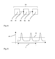
- the flow sensor 37 outputs a corresponding periodic measurement signal 41 from.
- the evaluation device 38 evaluates the measurement signal 41 of the flow sensor 37 with regard to the occurrence of the periodicity.
- the evaluation device 38 reports an error 42 when the measurement signal for a predetermined duration T has a constant level.
- the predetermined duration T is greater than the typical duration for a complete rotation of the suction drill 4 about the working axis 13.
- the duration is for example in the range of 100 ms to 1 s.
- the evaluation device 38 compares the measurement signal 41 with a threshold value 43.
- the measurement signal 41 must be at least once greater than the threshold value 43 and once less than the threshold value 43 within the predetermined duration T.
- a timekeeper is reset each time the measurement signal 41 exceeds the threshold value 43 , ie, the air flow strikes the flag 44 . If the reset remains off until the time T, the error signal 42 is output.
- the error signal 42 is associated with clogging of the suction drill 2 by cuttings. Although the fan 23 sucks air from the suction head 26 , no air exits from the suction opening 22 of the suction drill 2 .
- the error signal 42 can be communicated to the user by means of a display 39 or acoustically. Alternatively or additionally, the evaluation device 38 transmits the error signal to the hammer drill 1 , which then shuts off its electric motor 6 .
- the flow sensor 37 has, for example, a flag 44 whose sensor surface is parallel to the working axis 13 and the working axis 13 faces.
- the flag 44 is deflected by the air flow in the radial direction.
- the flag 44 is suspended on a piezoelectric sensor 45 .
- the deflection of the flag 44 generates a voltage pulse in the sensor 45.
- the flag 44 is narrow in the circumferential direction 46 and extends along the working axis 13 over at least half the length 34 of the cavity 28.
- the flag 44 is preferably a small distance from the suction drill 3.
- the distance to the working axis 13 is less than 55% of the diameter of the connecting portion 21 of the suction drill 4.
- the measuring signal 41 in the impingement of the air flow in radial direction on the sensor surface 44 changes.
- a pressure cell with a working axis 13 facing membrane or a planar piezoelectric pressure sensor can be used.
- the sensor surface 44 is arranged at a small distance from the suction drill 3 .
- the flow sensor 37 may be shielded in the circumferential direction 46 by walls 47 .
- the monitoring device 36 may receive a control signal from the hammer drill 1 , which indicates when the tool holder 4 and thus the suction drill 3 is rotated.
- the control signal can also transmit the speed, for example.
- the monitoring device 36 is activated in response to the control signal when the tool holder 4 rotates.
- the duration T can be set as a function of the speed, for example, the duration T is between 150% and 300% of the inverse of the speed.
Landscapes
- Engineering & Computer Science (AREA)
- Mechanical Engineering (AREA)
- Percussive Tools And Related Accessories (AREA)
- Processing Of Stones Or Stones Resemblance Materials (AREA)
- Drilling And Boring (AREA)
Priority Applications (5)
| Application Number | Priority Date | Filing Date | Title |
|---|---|---|---|
| EP14168923.2A EP2946860A1 (fr) | 2014-05-20 | 2014-05-20 | Dispositif d'aspiration |
| US15/312,475 US10759035B2 (en) | 2014-05-20 | 2015-05-13 | Suction extraction device |
| PCT/EP2015/060545 WO2015177010A1 (fr) | 2014-05-20 | 2015-05-13 | Dispositif d'aspiration |
| CN201580025394.9A CN106413956B (zh) | 2014-05-20 | 2015-05-13 | 抽吸装置 |
| EP15722199.5A EP3145665B1 (fr) | 2014-05-20 | 2015-05-13 | Dispositif d'aspiration |
Applications Claiming Priority (1)
| Application Number | Priority Date | Filing Date | Title |
|---|---|---|---|
| EP14168923.2A EP2946860A1 (fr) | 2014-05-20 | 2014-05-20 | Dispositif d'aspiration |
Publications (1)
| Publication Number | Publication Date |
|---|---|
| EP2946860A1 true EP2946860A1 (fr) | 2015-11-25 |
Family
ID=50732838
Family Applications (2)
| Application Number | Title | Priority Date | Filing Date |
|---|---|---|---|
| EP14168923.2A Withdrawn EP2946860A1 (fr) | 2014-05-20 | 2014-05-20 | Dispositif d'aspiration |
| EP15722199.5A Active EP3145665B1 (fr) | 2014-05-20 | 2015-05-13 | Dispositif d'aspiration |
Family Applications After (1)
| Application Number | Title | Priority Date | Filing Date |
|---|---|---|---|
| EP15722199.5A Active EP3145665B1 (fr) | 2014-05-20 | 2015-05-13 | Dispositif d'aspiration |
Country Status (4)
| Country | Link |
|---|---|
| US (1) | US10759035B2 (fr) |
| EP (2) | EP2946860A1 (fr) |
| CN (1) | CN106413956B (fr) |
| WO (1) | WO2015177010A1 (fr) |
Cited By (2)
| Publication number | Priority date | Publication date | Assignee | Title |
|---|---|---|---|---|
| DE102017008875B3 (de) * | 2017-04-23 | 2017-12-14 | Claudio Crazzolara | Flugfähige Vorrichtung und Verfahren zum Einsammeln von Aerosolpartikeln aus der Luft |
| US11298788B2 (en) | 2018-06-19 | 2022-04-12 | Makita Corporation | Electric power tool dust collection system |
Families Citing this family (13)
| Publication number | Priority date | Publication date | Assignee | Title |
|---|---|---|---|---|
| DE102014223043A1 (de) * | 2014-11-12 | 2016-05-12 | Robert Bosch Gmbh | Handwerkzeugmaschinenvorrichtung |
| US10493579B2 (en) * | 2016-08-03 | 2019-12-03 | Robert Bosch Tool Corporation | Dust collection system for a rotary power tool |
| EP3311951A1 (fr) * | 2016-10-20 | 2018-04-25 | HILTI Aktiengesellschaft | Procédé de commande et module d'aspirateur |
| DE102017206975A1 (de) * | 2017-04-26 | 2018-10-31 | Robert Bosch Gmbh | Zubehörvorrichtung für eine Handwerkzeugmaschine |
| DE102017219447A1 (de) * | 2017-10-30 | 2019-05-02 | Robert Bosch Gmbh | Absaugadapter |
| CN108326344A (zh) * | 2018-04-02 | 2018-07-27 | 西南交通大学 | 一种深孔加工抽屑器 |
| EP3883727A4 (fr) | 2018-11-19 | 2023-03-15 | Milwaukee Electric Tool Corporation | Collecteur de poussière comprenant un mécanisme de nettoyage de filtre |
| DE102018222772A1 (de) * | 2018-12-21 | 2020-06-25 | Robert Bosch Gmbh | Abnehmbare Staubauffangvorrichtung, insbesondere abnehmbarer Staubauffangbehälter, für eine Handwerkzeugmaschine |
| CN110037350B (zh) * | 2019-04-30 | 2022-10-28 | 深圳麦克韦尔科技有限公司 | 一种电子雾化装置及其控制方法 |
| EP4007673A4 (fr) * | 2019-08-01 | 2023-11-22 | Milwaukee Electric Tool Corporation | Ensemble trépan à vide avec mèche remplaçable |
| CN111152064B (zh) * | 2020-02-19 | 2021-07-27 | 湖州博星科技有限公司 | 一种钻头清洁便捷的清洁型钻孔系统 |
| CN219665906U (zh) | 2020-03-25 | 2023-09-12 | 米沃奇电动工具公司 | 用于与手持式动力工具一起使用的灰尘收集器 |
| CN111466581B (zh) * | 2020-04-14 | 2021-12-21 | 武汉轻工大学 | 百香果加工机 |
Citations (4)
| Publication number | Priority date | Publication date | Assignee | Title |
|---|---|---|---|---|
| US4711609A (en) * | 1982-06-29 | 1987-12-08 | Sita Baulemente Gmbh | Drill tool |
| US20050034715A1 (en) * | 2001-06-13 | 2005-02-17 | Terpstra Enterprises Pty Ltd. | Extraction apparatus |
| DE102006031507A1 (de) * | 2006-07-07 | 2008-01-17 | Robert Bosch Gmbh | Staubabsaugadaptervorrichtung |
| US20130136549A1 (en) | 2011-11-29 | 2013-05-30 | Hilti Aktiengesellschaft | Suction device and control method |
Family Cites Families (36)
| Publication number | Priority date | Publication date | Assignee | Title |
|---|---|---|---|---|
| GB2131950B (en) * | 1982-12-17 | 1986-04-03 | Marconi Co Ltd | Ceramic vane for use in monitoring flow of a fluid |
| US5440193A (en) * | 1990-02-27 | 1995-08-08 | University Of Maryland | Method and apparatus for structural, actuation and sensing in a desired direction |
| US5278620A (en) * | 1992-07-08 | 1994-01-11 | Xerox Corporation | Cleaning blade equipped with a vibration sensor |
| US6455186B1 (en) | 1998-03-05 | 2002-09-24 | Black & Decker Inc. | Battery cooling system |
| DE19810192A1 (de) * | 1998-03-10 | 1999-09-16 | Hilti Ag | Bohrwerkzeug |
| DE19810193A1 (de) * | 1998-03-10 | 1999-09-16 | Hilti Ag | Bohrwerkzeug |
| DE10000013A1 (de) * | 2000-01-03 | 2001-07-12 | Hilti Ag | Saugbohrer |
| DE10000015A1 (de) * | 2000-01-03 | 2001-07-12 | Hilti Ag | Saugwerkzeug |
| DE10115116A1 (de) * | 2001-03-27 | 2002-10-10 | Hilti Ag | Staubabsaugung für ein Handwerkzeuggerät |
| US20030075936A1 (en) * | 2001-10-19 | 2003-04-24 | Taiwan Semiconductor Manufacturing Co., Ltd. | Wafer blade equipped with piezoelectric sensors |
| US6609985B2 (en) * | 2001-11-07 | 2003-08-26 | Borgwarner Inc. | Tensioner with vibrational damping |
| JP2005145041A (ja) * | 2003-10-23 | 2005-06-09 | Ishihara Kikai Kogyo Kk | ノンコアタイプビット、ノンコアドリル装置およびその冷却水給排水方法 |
| US20060137681A1 (en) * | 2004-12-28 | 2006-06-29 | Ric Investments, Llc. | Actuator for a metered dose inhaler |
| US7563060B2 (en) * | 2005-10-13 | 2009-07-21 | The Boeing Company | Vacuum drilling system |
| US20070193759A1 (en) * | 2006-02-21 | 2007-08-23 | Sweig Brian M | Dust suppression boot for a power tool |
| US20090026881A1 (en) * | 2007-07-26 | 2009-01-29 | Hakan Erturk | Piezoelectric fan, method of cooling a microelectronic device using same, and system containing same |
| GB0723914D0 (en) | 2007-12-07 | 2008-01-23 | Johnson Electric Sa | A power tool |
| US20090193614A1 (en) * | 2008-02-06 | 2009-08-06 | Moore Carl P | Dust collection apparatus for demolition tool |
| US8967923B2 (en) * | 2012-01-13 | 2015-03-03 | Aeg Electric Tools Gmbh | Dust suction device for drilling machine |
| CA2724381A1 (fr) * | 2008-06-03 | 2009-12-10 | Atlas Copco Rock Drills Ab | Dispositif et procede comprenant une tete de rincage pour une perforatrice, et perforatrice comprenant le dispositif |
| JP5575429B2 (ja) * | 2009-07-10 | 2014-08-20 | 株式会社マキタ | 集塵アタッチメント |
| DE102009054970A1 (de) * | 2009-12-18 | 2011-06-22 | Hilti Aktiengesellschaft | Staubabsaugeinrichtung |
| JP5615725B2 (ja) | 2010-03-16 | 2014-10-29 | 株式会社マキタ | アタッチメント付き電動工具 |
| JP5448951B2 (ja) | 2010-03-16 | 2014-03-19 | 株式会社マキタ | アタッチメント付き電動工具の駆動源供給システム |
| JP5463464B2 (ja) * | 2010-04-12 | 2014-04-09 | Uht株式会社 | 穿孔装置 |
| JP5802893B2 (ja) * | 2011-05-18 | 2015-11-04 | Uht株式会社 | ドリル及びそれを用いた穿孔装置 |
| US8934263B2 (en) * | 2011-08-01 | 2015-01-13 | Honeywell International Inc. | Protective cover for pressure sensor assemblies |
| US9056379B2 (en) * | 2011-09-07 | 2015-06-16 | Makita Corporation | Power tool dust collecting device and power tool |
| DE102011087360A1 (de) | 2011-11-29 | 2013-05-29 | Hilti Aktiengesellschaft | Absaugvorrichtung |
| US9579432B2 (en) * | 2012-09-05 | 2017-02-28 | Heartware, Inc. | VAD integrated flow sensor |
| JP6131565B2 (ja) * | 2012-10-26 | 2017-05-24 | マックス株式会社 | 綴じ機 |
| SE536711C2 (sv) | 2012-10-29 | 2014-06-10 | Atlas Copco Rock Drills Ab | Dämpningsanordning för slagverk, slagverk, bergborrmaskin och förfarande för dämpning vid en bergborrmaskin |
| EP2803310A1 (fr) * | 2013-05-17 | 2014-11-19 | HILTI Aktiengesellschaft | Dispositif d'aspiration de poussière pour une machine-outil manuelle |
| US9316514B2 (en) * | 2014-03-26 | 2016-04-19 | Rosemount Inc. | High pressure wafer style magnetic flowmeter |
| PL3132903T3 (pl) * | 2014-04-15 | 2021-12-27 | Kabushiki Kaisha Miyanaga | Wiertło |
| DE102017206975A1 (de) * | 2017-04-26 | 2018-10-31 | Robert Bosch Gmbh | Zubehörvorrichtung für eine Handwerkzeugmaschine |
-
2014
- 2014-05-20 EP EP14168923.2A patent/EP2946860A1/fr not_active Withdrawn
-
2015
- 2015-05-13 EP EP15722199.5A patent/EP3145665B1/fr active Active
- 2015-05-13 US US15/312,475 patent/US10759035B2/en active Active
- 2015-05-13 CN CN201580025394.9A patent/CN106413956B/zh active Active
- 2015-05-13 WO PCT/EP2015/060545 patent/WO2015177010A1/fr active Application Filing
Patent Citations (4)
| Publication number | Priority date | Publication date | Assignee | Title |
|---|---|---|---|---|
| US4711609A (en) * | 1982-06-29 | 1987-12-08 | Sita Baulemente Gmbh | Drill tool |
| US20050034715A1 (en) * | 2001-06-13 | 2005-02-17 | Terpstra Enterprises Pty Ltd. | Extraction apparatus |
| DE102006031507A1 (de) * | 2006-07-07 | 2008-01-17 | Robert Bosch Gmbh | Staubabsaugadaptervorrichtung |
| US20130136549A1 (en) | 2011-11-29 | 2013-05-30 | Hilti Aktiengesellschaft | Suction device and control method |
Cited By (3)
| Publication number | Priority date | Publication date | Assignee | Title |
|---|---|---|---|---|
| DE102017008875B3 (de) * | 2017-04-23 | 2017-12-14 | Claudio Crazzolara | Flugfähige Vorrichtung und Verfahren zum Einsammeln von Aerosolpartikeln aus der Luft |
| DE202017002114U1 (de) * | 2017-04-23 | 2018-07-25 | Claudio Crazzolara | Flugfähige Vorrichtung zum Einsammeln von Aerosolpartikeln aus der Luft |
| US11298788B2 (en) | 2018-06-19 | 2022-04-12 | Makita Corporation | Electric power tool dust collection system |
Also Published As
| Publication number | Publication date |
|---|---|
| EP3145665B1 (fr) | 2018-03-07 |
| US10759035B2 (en) | 2020-09-01 |
| CN106413956A (zh) | 2017-02-15 |
| US20170087707A1 (en) | 2017-03-30 |
| EP3145665A1 (fr) | 2017-03-29 |
| CN106413956B (zh) | 2018-09-11 |
| WO2015177010A1 (fr) | 2015-11-26 |
Similar Documents
| Publication | Publication Date | Title |
|---|---|---|
| EP3145665B1 (fr) | Dispositif d'aspiration | |
| EP3529002B1 (fr) | Procédé de commande et module d'aspirateur | |
| EP2512731B1 (fr) | Équipement de dépoussiérage | |
| EP3221088B1 (fr) | Procédé de commande d'une perceuse | |
| DE102004017939A1 (de) | Geführte Werkzeugmaschine sowie Verfahren zum Betreiben einer geführten Werkzeugmaschine | |
| DE29901724U1 (de) | Vorrichtung mit flexibler Welle zur Gewinnung von Knochenspänen | |
| EP3576905A1 (fr) | Dispositif accessoire conçu pour une machine-outil | |
| DE19543599B4 (de) | Absaugeinrichtung für beim Bohren entstehenden Bohrstaub | |
| EP2669060A1 (fr) | Machine-outil de burinage | |
| WO2011020459A1 (fr) | Sonde de mesure de pression | |
| EP3325212B1 (fr) | Machine-outil portative et procede avec celle-ci | |
| DE3939538A1 (de) | Richtungsbohrwerkzeug | |
| DE19603528A1 (de) | Handwerkzeugmaschine | |
| EP3843941B1 (fr) | Dispositif d'aspiration de poussière | |
| EP1340596A1 (fr) | Mécanisme de percussion à ressort pneumatique | |
| DE102016117687A1 (de) | Bohrlochreinigungsvorrichtung | |
| EP3225967B1 (fr) | Dispositf de détection d'un endommagement pour un roulement de palier à rotation lente | |
| EP0558994A1 (fr) | Outil à main | |
| WO1999058984A1 (fr) | Dispositif permettant de detecter le nombre de tours d'un mecanisme actionne par un fluide | |
| EP3369864B1 (fr) | Procédé de détection d'obstacles lors du fonctionnement d'un vibrateur de battage | |
| DE10161187A1 (de) | Gesteinsbohrkopf | |
| DE10043415B4 (de) | Saugkappe für ein Handwerkzeuggerät | |
| DE1210376B (de) | Drehschlagbohrhammer zum Bearbeiten von Teilen von Bauwerken aus Beton u. dgl. | |
| DE931100C (de) | Drehvorrichtung zur Erleichterung des Eintreibens oder Herausziehens von Pfaehlen, Vortreibrohren od. dgl. | |
| DE19750018C2 (de) | Meßeinrichtung für Vollschnittmaschinen im Hart-, Weich- und Lockergesteinsvortrieb zum Feststellen des Verschleißes der an Bohrkopf angeordneten Werkzeuge |
Legal Events
| Date | Code | Title | Description |
|---|---|---|---|
| PUAI | Public reference made under article 153(3) epc to a published international application that has entered the european phase |
Free format text: ORIGINAL CODE: 0009012 |
|
| AK | Designated contracting states |
Kind code of ref document: A1 Designated state(s): AL AT BE BG CH CY CZ DE DK EE ES FI FR GB GR HR HU IE IS IT LI LT LU LV MC MK MT NL NO PL PT RO RS SE SI SK SM TR |
|
| AX | Request for extension of the european patent |
Extension state: BA ME |
|
| STAA | Information on the status of an ep patent application or granted ep patent |
Free format text: STATUS: THE APPLICATION IS DEEMED TO BE WITHDRAWN |
|
| 18D | Application deemed to be withdrawn |
Effective date: 20160526 |