EP1525924A2 - Maschine zum Auftragen eines flüssigen oder pastösen Auftragmediums auf die Oberfläche einer laufenden Materialbahn - Google Patents
Maschine zum Auftragen eines flüssigen oder pastösen Auftragmediums auf die Oberfläche einer laufenden Materialbahn Download PDFInfo
- Publication number
- EP1525924A2 EP1525924A2 EP04105002A EP04105002A EP1525924A2 EP 1525924 A2 EP1525924 A2 EP 1525924A2 EP 04105002 A EP04105002 A EP 04105002A EP 04105002 A EP04105002 A EP 04105002A EP 1525924 A2 EP1525924 A2 EP 1525924A2
- Authority
- EP
- European Patent Office
- Prior art keywords
- medium
- application
- material web
- machine according
- running
- Prior art date
- Legal status (The legal status is an assumption and is not a legal conclusion. Google has not performed a legal analysis and makes no representation as to the accuracy of the status listed.)
- Ceased
Links
- 239000007788 liquid Substances 0.000 title claims description 3
- 235000011837 pasties Nutrition 0.000 title claims description 3
- 238000000576 coating method Methods 0.000 title abstract description 6
- 239000011248 coating agent Substances 0.000 title abstract description 5
- 239000000463 material Substances 0.000 claims description 54
- 239000011111 cardboard Substances 0.000 claims description 2
- 230000005484 gravity Effects 0.000 claims description 2
- 238000000034 method Methods 0.000 claims description 2
- 239000011087 paperboard Substances 0.000 claims description 2
- 238000002203 pretreatment Methods 0.000 claims description 2
- 239000000758 substrate Substances 0.000 claims 6
- 230000003247 decreasing effect Effects 0.000 claims 1
- 238000011065 in-situ storage Methods 0.000 abstract 1
- 230000000717 retained effect Effects 0.000 abstract 1
- 230000000630 rising effect Effects 0.000 description 7
- 239000000243 solution Substances 0.000 description 4
- 239000012530 fluid Substances 0.000 description 2
- 238000002360 preparation method Methods 0.000 description 2
- 230000005540 biological transmission Effects 0.000 description 1
- 230000005574 cross-species transmission Effects 0.000 description 1
- 239000000123 paper Substances 0.000 description 1
- 238000011144 upstream manufacturing Methods 0.000 description 1
- 230000003313 weakening effect Effects 0.000 description 1
Images

Classifications
-
- B—PERFORMING OPERATIONS; TRANSPORTING
- B05—SPRAYING OR ATOMISING IN GENERAL; APPLYING FLUENT MATERIALS TO SURFACES, IN GENERAL
- B05C—APPARATUS FOR APPLYING FLUENT MATERIALS TO SURFACES, IN GENERAL
- B05C5/00—Apparatus in which liquid or other fluent material is projected, poured or allowed to flow on to the surface of the work
- B05C5/005—Curtain coaters
-
- B—PERFORMING OPERATIONS; TRANSPORTING
- B05—SPRAYING OR ATOMISING IN GENERAL; APPLYING FLUENT MATERIALS TO SURFACES, IN GENERAL
- B05C—APPARATUS FOR APPLYING FLUENT MATERIALS TO SURFACES, IN GENERAL
- B05C11/00—Component parts, details or accessories not specifically provided for in groups B05C1/00 - B05C9/00
- B05C11/10—Storage, supply or control of liquid or other fluent material; Recovery of excess liquid or other fluent material
- B05C11/1039—Recovery of excess liquid or other fluent material; Controlling means therefor
Definitions
- the invention relates to a machine for applying a liquid or pasty application medium by means of at least one commissioned work on the Surface of a running material web, in particular made of paper or Carton, wherein the commissioned work the order medium from a Dispensing opening arrangement, in particular slot nozzle, directly or under mediation of at least one guide surface in the form of a Gravity influence and / or under the influence of further forces towards a running background of moving curtain or veil, where with direct order the running underground the surface of the Material web is and in the case of indirect order the running underground Surface of a transmission element, preferably one Transfer roller, which is the application medium then to the Surface of the material web transfers, with the machine in assignment to the commissioned work or a discharge opening arrangement having Dispensing part of the commissioned work a medium catcher, if necessary collecting tray or gutter, to catch from the Dispensing opening arrangement dispensed order medium in Business interruption phases.
- Such machines are known in many forms.
- conventional is the commissioned work or the discharge opening arrangement having Dispensing part stationary in operation.
- the at short-term Business interruption, e.g. a web break, to catch the Application medium serving catcher is between a collection position, in he or she catches the order medium curtain or veil, and one Adjustable order position, in which he laterally or in the direction of the Material web is arranged next to the commissioned work or the delivery part, such that the dispensed from the discharge opening arrangement Medium curtain or medium curtain unhindered to the running Underground meets.
- the catcher In addition to exceptional operating conditions, such as web break, The catcher also comes when starting up and shutting down the machine used to start in the initial phase or in the final phase at shutdown, temporarily from the discharge port assembly collected and dissipate discharged application medium. It will be in This connection, for example, to DE 197 35 980 A1, DE 198 23 686 A1, DE 199 03 559 A1 and US 5,773,093.
- the conventional medium catcher often in the form of a gutter is executed and the captured application medium in the transverse direction to Run direction dissipates the material web, conventionally must be relatively compact be executed, on the one hand, in view of the fact that the curtain is not a has such high height, so the discharge opening arrangement is not too high above the current underground, as well as on the other hand in the With regard to a not too large inertia, in the adjustment of the Catcher could be a hindrance or a problem. It follows the problem that with highly viscous media and / or very broad Machines a proper discharge of the collected medium difficult or even impossible to guarantee, or at most only at the cost of a too high curtain height.
- the object of the invention is the machine so educate that the drainage of trapped by the interceptor, highly viscous coating medium and / or of these through a very wide material web captured order medium can be ensured can.
- the commissioned work or the dispensing part in the machine during operation is adjustable between a collection position in which the medium catcher from the Dispensing opening arrangement dispensed order medium, and an order position in which from the dispensing opening arrangement discharged application medium hits the running surface.
- the medium catcher itself can, at least in the normal continuous operation of the machine, be positionally stable. This will be one "Spillover" of the captured application medium due to a Adjustment of the medium catcher reliably avoided. Furthermore, the plays Mass inertia of the interceptor no longer matters. They are larger overall Medium catcher, if necessary gutters and / or discharge chutes, possible, before all in connection with an at least partial removal of the Application medium in the direction of the web or against the Direction of the material web to a fluid drain or to a in Transverse to the material web running medium trough.
- the medium catcher on certain occasions is wegphal, so far not completely stationary. This can For example, in the case of Bahnetzmentss (threading), for example after a demolition of the railway be the case, in which the machine is also in in a certain sense "running". It is therefore in the above of "normal running operation" of the machine the speech in which the Medium catcher is positionally fixed according to a design option.
- the catching position can be behind in the running direction of the running underground the order position so that a point of the current underground, especially the material web, first the order position and then the Catching position happens.
- This embodiment is above all, but not exclusively, then advantageous if the material web in the area of Fall arrest position or / and horizontally or in the area of the order position Running direction of the web is sloping.
- Another possibility is that the catching position in the direction of the running underground in front of the order position, leaving a post of the running underground, especially the material web, first the Trapping position and then the order position happens.
- This embodiment is particularly advantageous (but not exclusive) if the Material web in the area of the collecting position and / or in the area of Application position rising horizontally or in the running direction of the material web runs.
- the commissioned work or the Dispensing part in the collection position above the medium catcher is arranged, and that at least during operation of the machine Medium catcher over a portion of the moving web is arranged. It can be provided that below the Medium catcher a web deflection for deflecting the material web by at least one deflection angle and / or a Job preparation facility for the preparation of the contract of the Application medium is arranged on the surface of the material web.
- the Web deflection or / and the job pretreatment device can with be integrated with the medium catcher to a unit.
- the addressed job pretreatment is, for example, to a so-called Aircut or air boundary layer scraper or Heilgrenz Anlagenabsauger or the like, which is one of the Material web entrained air boundary layer weakens or removes to improve the order result.
- a preferred Embodiment is characterized in that the material web in Area of the catching position and in the area of the order position in Running direction sloping. This embodiment is particularly then advantageous if the catching position in the running direction of the current Background behind the order position, because then based on a Given curtain height at the order position comparatively much Space to be provided in the height direction for the medium catcher can.
- Another preferred embodiment is characterized in that the material web in the area of the collecting position and in the area of Order position in the running direction rising. This embodiment is especially advantageous when the catching position in Running direction of the current underground lies before the order position. It can then turn to a given curtain height at the Order position comparatively much space in height direction for the Medium catcher be provided.
- the medium catcher be designed for this is the trapped application medium in the direction of the web or against the direction of the web to a fluid drain or to a medium trough running transversely to the material web dissipate.
- the invention further provides a method for operating a machine according to the invention ready.
- the commissioned work or the delivery part is adjusted by the collection position in which the medium catcher from the Dispensing opening arrangement dispensed order medium, in the Order position, in the dispensed from the dispensing opening arrangement Order medium meets the running underground or / and that to Ending or interrupting the order the commissioned work or the Dispensing part from the order position (back again) to the collection position is adjusted.
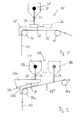
- Fig. 1 shows schematically a curtain applicator 10 in one Coating machine for direct curtain application on a material web 12 is made of paper or cardboard.
- the over a pulleys 14 and 16 comprehensive guide arrangement guided material web 12 runs below a curtain applicator head 18 of the commissioned work.
- the curtain order header has in the usual way one in the transverse direction to the direction the material web extending distribution chamber 20 and one in the same Direction extending slot 22 on which the curtain or veil 24 from application medium, in particular coating color dispenses.
- the curtain or Veil 24 hits a horizontally extending portion 12 'of Material web 12.
- Job pre-treatment device for example a so-called Aircut, Air boundary layer scraper or Heilgrenz Anlagenabsaugung upstream be denoted by 28 and in the region of the guide roller 14 on the Material web 12 acts.
- the movably arranged leads Gutter the collected application medium in the transverse direction to Running direction of the web from.
- This requires at high viscosity Order media or / and large web widths due to the Discharge required gradients of the gutter in the transverse direction to Direction of the material web a corresponding space requirement in Height direction, resulting in a correspondingly high, may not desired arrangement of the application head 18 above the Material web section 12 'results.
- the Medium catcher 26 a stationarily arranged and with the Job pretreatment device 28a integrated into a unit.
- the curtain applicator head 18a may be between one shown in FIG solid lines shown in the curtain, the curtain of Medium catcher 26a is caught, and dashed in Fig. 2 illustrated order position mechanically adjustable, in which the application head 18a on a rising in the direction of the web 12 Material web section 12 'applies.
- the medium catcher as stationary, as comparatively large Drip tray or designed as a comparatively large collection container be. Due to the rising in the direction of the course of Material web section 12 "in combination with the adjustability of Application head 18a between the collection position and the order position, As shown in Fig. 2, for the medium catcher particularly large amount of space be provided in height direction, without thereby a large curtain height, so a large distance between the outlet of Slot nozzle 22 and the web portion 12 "in the order position the application head 18a is conditional.
- the curtain height referred to the surface of the web portion 12 is in the Catching position greater than in the order item, and the difference between these heights stands as additional space in the height direction for the medium catcher available.
- FIG. 3 differs from the Embodiment of Fig. 2 by another material web guide.
- the media catcher 36b Apart from the direction of the web, is the media catcher 36b relative to the web substantially the same positioned and formed as in the case of FIG. 2. That in the Auffangposition of the application head 18b trapped application medium is accordingly after collecting first in the running direction of the material web dissipated, as symbolized by the arrow M.
- the Mediumaufflinder integrated job pretreatment device 28a is now a job pretreatment device 28b in the direction behind the Order position arranged so that the material web before the order there pretreatment, such as air boundary layer weakening or removal, is subjected.
Landscapes
- Coating Apparatus (AREA)
- Paper (AREA)
Abstract
Description
- Fig. 1
- zeigt eine Lösung des Standes der Technik, nämlich ein Vorhang-Auftragswerk mit zwischen einer Auffangposition und einer Auftragsposition verstellbaren Mediumauffangrinne, die das aufgefangene Auftragsmedium in Querrichtung zur Laufrichtung der Materialbahn abführt.
- Fig. 2
- zeigt ein erstes Ausführungsbeispiel der Erfindung mit einem zwischen einer Auffangposition und einer Auftragsposition in Laufrichtung der Materialbahn verstellbaren Vorhang-Auftragskopf, der auf einen in Laufrichtung ansteigend verlaufenden Materialbahnabschnitt aufträgt.
- Fig. 3
- zeigt ein weiteres Ausführungsbeispiel der Erfindung mit einem zwischen einer Auffangposition und einer Auftragsposition in Laufrichtung der Materialbahn verstellbaren Vorhang-Auftragskopf, der auf einen in Laufrichtung der Materialbahn abfallend verlaufenden Materialbahnabschnitt aufträgt.
Claims (15)
- Maschine zum Auftragen eines flüssigen oder pastösen Auftragsmediums mittels wenigstens eines Auftragswerks (10) auf die Oberfläche einer laufenden Materialbahn (12) insbesondere aus Papier oder Karton,
wobei das Auftragswerk das Auftragsmedium aus einer Abgabeöffnungsanordnung, insbesondere Schlitzdüse (22), unmittelbar oder unter Vermittlung wenigstens einer Führungsfläche, in Form eines sich unter Schwerkrafteinfluss oder/und unter Einfluss weiterer Kräfte hin zu einem laufenden Untergrund bewegenden Vorhangs oder Schleiers (24) abgibt,
wobei bei direktem Auftrag der laufende Untergrund die Oberfläche der Materialbahn (12) ist und bei indirektem Auftrag der laufende Untergrund die Oberfläche eines Übertragungselements, vorzugsweise einer Übertragungswalze, ist, welches das Auftragsmedium dann an die Oberfläche der Materialbahn überträgt,
wobei die Maschine in Zuordnung zum Auftragswerk oder einem die Abgabeöffnungsanordnung aufweisenden Abgabeteil (18) des Auftragswerks einen Mediumauffänger (26), ggf. Auffangwanne oder Auffangrinne, aufweist, zum Auffangen von aus der Abgabeöffnungsanordnung (22) abgegebenem Auftragsmedium in Betriebsunterbrechungsphasen,
dadurch gekennzeichnet, dass das Auftragswerk oder das Abgabeteil (18a; 18b) in der Maschine im laufenden Betrieb verstellbar ist zwischen einer Auffangposition, in der der Mediumauffänger (26a; 16b) aus der Abgabeöffnungsanordnung (22) abgegebenes Auftragsmedium auffängt, und einer Auftragsposition, in der aus der Abgabeöffnungsanordnung (22) abgegebenes Auftragsmedium auf den laufenden Untergrund (12) trifft. - Maschine nach Anspruch 1, dadurch gekennzeichnet, dass der Mediumauffänger (26a; 26b) zumindest im normal laufenden Betrieb der Maschine positionsfest ist.
- Maschine nach Anspruch 1 oder 2, dadurch gekennzeichnet, dass die Auffangposition und die Auftragsposition in Laufrichtung des laufenden Untergrunds (12) oder/und in Laufrichtung der Materialbahn (12) gegeneinander versetzt sind.
- Maschine nach Anspruch 3, dadurch gekennzeichnet, dass die Auffangposition in Laufrichtung des laufenden Untergrunds (12) hinter der Auftragsposition liegt.
- Maschine nach Anspruch 3, dadurch gekennzeichnet, dass die Auffangposition in Laufrichtung des laufenden Untergrunds (12) vor der Auftragsposition liegt.
- Maschine nach einem der Ansprüche 1 bis 5, dadurch gekennzeichnet, dass das Auftragswerk oder das Abgabeteil (18a; 18b) in der Auffangposition oberhalb des Mediumauffängers (26a; 26b) angeordnet ist, und dass zumindest im laufenden Betrieb der Maschine der Mediumauffänger (26a; 26b) über einem Abschnitt (12'; 12") der laufenden Materialbahn (12) angeordnet ist.
- Maschine nach Anspruch 6, dadurch gekennzeichnet, dass unterhalb des Mediumauffängers (26a; 26b) eine Bahnumlenkung (14a; 14b) zur Umlenkung der Materialbahn um wenigstens einen Umlenkwinkel angeordnet ist.
- Maschine nach Anspruch 6 oder 7, dadurch gekennzeichnet, dass eine Auftragsvorbehandlungseinrichtung (28a) zur Vorbereitung des Auftrags des Auftragsmediums auf die Oberfläche der Materialbahn (12) vorgesehen ist, die vorzugsweise unterhalb des Mediumauffängers (26a) angeordnet ist.
- Maschine nach Anspruch 7 oder 8, dadurch gekennzeichnet, dass die Bahnumlenkung oder/und die Auftragsvorbehandlungseinrichtung (28a) mit dem Mediumauffänger (26a) zu einer Baueinheit integriert ist.
- Maschine nach einem der Ansprüche 1 bis 9, dadurch gekennzeichnet, dass die Materialbahn (12) im Bereich der Auffangposition oder/und im Bereich der Auftragsposition in Laufrichtung ansteigend oder abfallend verläuft.
- Maschine nach Anspruch 10 und vorzugsweise wenigstens nach Anspruch 4, dadurch gekennzeichnet, dass die Materialbahn (12) im Bereich des Auffangposition und im Bereich der Auftragsposition in Laufrichtung abfallend verläuft.
- Maschine nach Anspruch 9 und vorzugsweise wenigstens nach Anspruch 5, dadurch gekennzeichnet, dass die Materialbahn (17) im Bereich des Auffangposition und im Bereich der Auftragsposition in Laufrichtung ansteigend verläuft.
- Maschine nach einem Ansprüche 1 bis 12, dadurch gekennzeichnet, dass der Mediumauffänger (26a; 26b) dafür ausgelegt ist, das aufgefangene Auftragsmedium in Laufrichtung der Materialbahn (12)oder entgegen der Laufrichtung der Materialbahn (12) zu einem Mediumabfluss (30a; 30b) oder zu einer in Querrichtung zur Materialbahn verlaufenden Mediumabflussrinne abzuführen.
- Maschine nach einem der Ansprüche 1 bis 13, gekennzeichnet durch eine hydraulische, pneumatische oder elektromotorisch Aktuatoranordnung zum bedarfsweisen Verstellen des Auftragswerks bzw. des Abgabeteils (18a; 18b) zwischen der Auffangposition und der Auftragsposition.
- Verfahren zum Betreiben einer Maschine nach einem der vorhergehenden Ansprüche,
dadurch gekennzeichnet, dass zum Starten des Auftragens das Auftragswerk oder das Abgabeteil (18a; 18b) verstellt wird von der Auffangposition, in der der Mediumauffänger (26a; 16b) aus der Abgabeöffnungsanordnung (22) abgegebenes Auftragsmedium auffängt, in die Auftragsposition, in der aus der Abgabeöffnungsanordnung (22) abgegebenes Auftragsmedium auf den laufenden Untergrund (12) trifft, oder/und dass zum Beenden oder Unterbrechen des Auftragens das Auftragswerk oder das Abgabeteil (18a; 18b) von der Auftragsposition (wieder zurück) in die Auffangposition verstellt wird.
Applications Claiming Priority (2)
| Application Number | Priority Date | Filing Date | Title |
|---|---|---|---|
| DE2003149117 DE10349117A1 (de) | 2003-10-22 | 2003-10-22 | Maschine zum Auftragen eines flüssigen oder pastösen Auftragsmediums auf die Oberfläche einer laufenden Materialbahn |
| DE10349117 | 2003-10-22 |
Publications (2)
| Publication Number | Publication Date |
|---|---|
| EP1525924A2 true EP1525924A2 (de) | 2005-04-27 |
| EP1525924A3 EP1525924A3 (de) | 2008-01-23 |
Family
ID=34384400
Family Applications (1)
| Application Number | Title | Priority Date | Filing Date |
|---|---|---|---|
| EP04105002A Ceased EP1525924A3 (de) | 2003-10-22 | 2004-10-13 | Maschine zum Auftragen eines flüssigen oder pastösen Auftragmediums auf die Oberfläche einer laufenden Materialbahn |
Country Status (2)
| Country | Link |
|---|---|
| EP (1) | EP1525924A3 (de) |
| DE (1) | DE10349117A1 (de) |
Cited By (2)
| Publication number | Priority date | Publication date | Assignee | Title |
|---|---|---|---|---|
| CN107511294A (zh) * | 2017-08-21 | 2017-12-26 | 江苏科德宝建筑节能科技有限公司 | 一种防水透气膜用浸润装置 |
| WO2018137932A1 (de) * | 2017-01-25 | 2018-08-02 | Voith Patent Gmbh | Vorhang-auftragswerk und verfahren zum auftragen eines auftragsmediums |
Citations (4)
| Publication number | Priority date | Publication date | Assignee | Title |
|---|---|---|---|---|
| DE19735980A1 (de) | 1996-08-20 | 1998-02-26 | Mitsubishi Paper Mills Ltd | Gerät zum Anfahren und Anhalten des Gießlackierens sowie das Auftragungsverfahren, welches selbiges verwendet |
| US5773093A (en) | 1995-06-02 | 1998-06-30 | Mitsubishi Paper Mills Limited | Apparatus for controlling application of excess coating liquid in curtain coating and method of coating |
| DE19823686A1 (de) | 1997-05-28 | 1999-01-07 | Mitsubishi Paper Mills Ltd | Verfahren und Einrichtung zum Florstreichen |
| DE19903559A1 (de) | 1998-01-30 | 1999-10-21 | Mitsubishi Paper Mills Ltd | Verfahren und Apparatur zur Vorhangbeschichtung |
Family Cites Families (7)
| Publication number | Priority date | Publication date | Assignee | Title |
|---|---|---|---|---|
| JPS5474761A (en) * | 1977-11-28 | 1979-06-15 | Fuji Photo Film Co Ltd | Production of heat-sensitive recording sheet |
| EP0003860B1 (de) * | 1978-03-01 | 1982-03-24 | Agfa-Gevaert N.V. | Verfahren zur Beschichtung einer Materialbahn mit mehreren übereinander angeordneten photographischen Schichten, nach dem Vorhang-Beschichtungs-Verfahren |
| US5017408A (en) * | 1990-08-08 | 1991-05-21 | Eastman Kodak Company | Curtain coating start/finish method and apparatus |
| JP4113985B2 (ja) * | 1998-07-22 | 2008-07-09 | 富士フイルム株式会社 | 塗布方法及び装置 |
| DE19954391A1 (de) * | 1999-11-12 | 2001-05-31 | Jagenberg Papiertech Gmbh | Vorrichtung zum Ermitteln von Beschichtungsparametern für einen Curtain-Coater |
| DE19962844A1 (de) * | 1999-12-23 | 2001-07-05 | Bachofen & Meier Ag Maschf | Verfahren und Vorrichtung zum Beschichten einer laufenden Materialbahn |
| EP1319747A2 (de) * | 2001-12-13 | 2003-06-18 | Dow Global Technologies Inc. | Verfahren und Vorrichtung zum Vorhangbeschichten |
-
2003
- 2003-10-22 DE DE2003149117 patent/DE10349117A1/de not_active Withdrawn
-
2004
- 2004-10-13 EP EP04105002A patent/EP1525924A3/de not_active Ceased
Patent Citations (4)
| Publication number | Priority date | Publication date | Assignee | Title |
|---|---|---|---|---|
| US5773093A (en) | 1995-06-02 | 1998-06-30 | Mitsubishi Paper Mills Limited | Apparatus for controlling application of excess coating liquid in curtain coating and method of coating |
| DE19735980A1 (de) | 1996-08-20 | 1998-02-26 | Mitsubishi Paper Mills Ltd | Gerät zum Anfahren und Anhalten des Gießlackierens sowie das Auftragungsverfahren, welches selbiges verwendet |
| DE19823686A1 (de) | 1997-05-28 | 1999-01-07 | Mitsubishi Paper Mills Ltd | Verfahren und Einrichtung zum Florstreichen |
| DE19903559A1 (de) | 1998-01-30 | 1999-10-21 | Mitsubishi Paper Mills Ltd | Verfahren und Apparatur zur Vorhangbeschichtung |
Cited By (3)
| Publication number | Priority date | Publication date | Assignee | Title |
|---|---|---|---|---|
| WO2018137932A1 (de) * | 2017-01-25 | 2018-08-02 | Voith Patent Gmbh | Vorhang-auftragswerk und verfahren zum auftragen eines auftragsmediums |
| US11407001B2 (en) | 2017-01-25 | 2022-08-09 | Voith Patent Gmbh | Curtain applicator and method for applying an application medium |
| CN107511294A (zh) * | 2017-08-21 | 2017-12-26 | 江苏科德宝建筑节能科技有限公司 | 一种防水透气膜用浸润装置 |
Also Published As
| Publication number | Publication date |
|---|---|
| EP1525924A3 (de) | 2008-01-23 |
| DE10349117A1 (de) | 2005-05-25 |
Similar Documents
| Publication | Publication Date | Title |
|---|---|---|
| EP1544353B1 (de) | Vorhang-Auftragsvorrichtung | |
| DE3220636A1 (de) | Vorrichtung zur bildungs eines faserbandes an karden | |
| EP1676957B1 (de) | Auftragsvorrichtung | |
| DE10349117A1 (de) | Maschine zum Auftragen eines flüssigen oder pastösen Auftragsmediums auf die Oberfläche einer laufenden Materialbahn | |
| DE20320514U1 (de) | Maschine zum Auftragen eines flüssigen oder pastösen Auftragsmediums auf die Oberfläche einer laufenden Materialbahn | |
| DE10034797C1 (de) | Streugerät | |
| DE102007000776A1 (de) | Auftragsvorrichtung | |
| EP1432525B1 (de) | Auftragsvorrichtung | |
| EP1801289A1 (de) | Verfahren und Vorrichtung zum Auftragen eines Auftragsmediums auf eine Materialbahn | |
| EP0937815B1 (de) | Vorrichtung und Verfahren zum Auftragen eines flüssigen oder pastösen Auftragsmediums auf eine laufende Materialbahn, insbesondere aus Papier oder Karton | |
| EP2067531A2 (de) | Randführung | |
| EP2111925A1 (de) | Vorhang-Auftragswerk | |
| EP1596004B1 (de) | Vorhangs-Auftragsvorrichtung | |
| EP1749585A2 (de) | Auftragsverfahren | |
| DE102008054889A1 (de) | Vorhang-Auftragswerk | |
| WO2008015042A1 (de) | Auftragsvorrichtung | |
| DE102008040405A1 (de) | Vorhang-Auftragswerk | |
| EP1118708B1 (de) | Auftragsvorrichtung | |
| WO1996007790A1 (de) | Auftragswerk zum direkten oder indirekten auftragen eines flüssigen oder pastösen mediums auf eine laufende materialbahn | |
| DE10349122A1 (de) | Maschine zum Auftragen eines flüssigen oder pastösen Auftragsmediums auf die beiden Oberflächen einer laufenden Materialbahn | |
| WO2008015043A1 (de) | Auftragsvorrichtung | |
| DE102007026619A1 (de) | Auftragsvorrichtung | |
| DE10349119A1 (de) | Vorhang-Auftragsverfahren und Vorhang-Auftragsmaschine zum Auftragen auf eine laufende Materialbahn | |
| EP2172592B1 (de) | Vorhang-Auftragswerk | |
| DE10359677A1 (de) | Verfahren zum einseitigen oder beidseitigen Vorhang- oder Schleierauftrag auf die Oberfläche einer laufenden Materialbahn, insbesondere aus Papier oder Karton |
Legal Events
| Date | Code | Title | Description |
|---|---|---|---|
| PUAI | Public reference made under article 153(3) epc to a published international application that has entered the european phase |
Free format text: ORIGINAL CODE: 0009012 |
|
| AK | Designated contracting states |
Kind code of ref document: A2 Designated state(s): AT BE BG CH CY CZ DE DK EE ES FI FR GB GR HU IE IT LI LU MC NL PL PT RO SE SI SK TR |
|
| AX | Request for extension of the european patent |
Extension state: AL HR LT LV MK |
|
| RAP1 | Party data changed (applicant data changed or rights of an application transferred) |
Owner name: VOITH PATENT GMBH |
|
| PUAL | Search report despatched |
Free format text: ORIGINAL CODE: 0009013 |
|
| AK | Designated contracting states |
Kind code of ref document: A3 Designated state(s): AT BE BG CH CY CZ DE DK EE ES FI FR GB GR HU IE IT LI LU MC NL PL PT RO SE SI SK TR |
|
| AX | Request for extension of the european patent |
Extension state: AL HR LT LV MK |
|
| 17P | Request for examination filed |
Effective date: 20080723 |
|
| AKX | Designation fees paid |
Designated state(s): AT BE BG CH CY CZ DE DK EE ES FI FR GB GR HU IE IT LI LU MC NL PL PT RO SE SI SK TR |
|
| 17Q | First examination report despatched |
Effective date: 20090128 |
|
| STAA | Information on the status of an ep patent application or granted ep patent |
Free format text: STATUS: THE APPLICATION HAS BEEN REFUSED |
|
| 18R | Application refused |
Effective date: 20090703 |