EP1524084B1 - Angetriebenes Schlagwerkzeug - Google Patents
Angetriebenes Schlagwerkzeug Download PDFInfo
- Publication number
- EP1524084B1 EP1524084B1 EP04256316A EP04256316A EP1524084B1 EP 1524084 B1 EP1524084 B1 EP 1524084B1 EP 04256316 A EP04256316 A EP 04256316A EP 04256316 A EP04256316 A EP 04256316A EP 1524084 B1 EP1524084 B1 EP 1524084B1
- Authority
- EP
- European Patent Office
- Prior art keywords
- torque
- impact
- rotation speed
- value
- driving shaft
- Prior art date
- Legal status (The legal status is an assumption and is not a legal conclusion. Google has not performed a legal analysis and makes no representation as to the accuracy of the status listed.)
- Expired - Lifetime
Links
- 230000007246 mechanism Effects 0.000 claims description 13
- 239000000463 material Substances 0.000 description 12
- 230000006870 function Effects 0.000 description 5
- 239000003638 chemical reducing agent Substances 0.000 description 3
- 238000010586 diagram Methods 0.000 description 3
- 230000009467 reduction Effects 0.000 description 3
- 238000000034 method Methods 0.000 description 2
- 238000012986 modification Methods 0.000 description 2
- 230000004048 modification Effects 0.000 description 2
- 230000008569 process Effects 0.000 description 2
- 238000007493 shaping process Methods 0.000 description 2
- 230000002159 abnormal effect Effects 0.000 description 1
- 230000001133 acceleration Effects 0.000 description 1
- 230000008901 benefit Effects 0.000 description 1
- 238000006073 displacement reaction Methods 0.000 description 1
- 238000001914 filtration Methods 0.000 description 1
Images


Classifications
-
- B—PERFORMING OPERATIONS; TRANSPORTING
- B25—HAND TOOLS; PORTABLE POWER-DRIVEN TOOLS; MANIPULATORS
- B25B—TOOLS OR BENCH DEVICES NOT OTHERWISE PROVIDED FOR, FOR FASTENING, CONNECTING, DISENGAGING OR HOLDING
- B25B21/00—Portable power-driven screw or nut setting or loosening tools; Attachments for drilling apparatus serving the same purpose
- B25B21/02—Portable power-driven screw or nut setting or loosening tools; Attachments for drilling apparatus serving the same purpose with means for imparting impact to screwdriver blade or nut socket
- B25B21/026—Impact clutches
-
- B—PERFORMING OPERATIONS; TRANSPORTING
- B25—HAND TOOLS; PORTABLE POWER-DRIVEN TOOLS; MANIPULATORS
- B25B—TOOLS OR BENCH DEVICES NOT OTHERWISE PROVIDED FOR, FOR FASTENING, CONNECTING, DISENGAGING OR HOLDING
- B25B23/00—Details of, or accessories for, spanners, wrenches, screwdrivers
- B25B23/14—Arrangement of torque limiters or torque indicators in wrenches or screwdrivers
- B25B23/1405—Arrangement of torque limiters or torque indicators in wrenches or screwdrivers for impact wrenches or screwdrivers
Definitions
- a fastening operation is automatically completed by stopping the driving of a driving source such as a motor, when a torque for fastening the fastening member reaches to a predetermined reference value previously set.
- a first conventional power impact tool shown in publication gazette of Japanese Patent Application 6-91551 , an actual torque, which is necessary for fastening the fastening member, is sensed and the driving of a motor is stopped when the actual torque reaches to a predetermined reference value.
- the first conventional power impact tool which stops the driving of the motor corresponding to the actual torque for fastening the fastening member needs a sensor provided on an output shaft for sensing the actual torque, so that it causes the cost increase and the damage of the usability owing to the upsizing of the power impact tool, even though the automatic stopping of the driving of the motor can be controlled precisely corresponding to the actual torque.
- a number of impact of a hammer is sensed and driving of a motor is automatically stopped when the number of impact reaches to a predetermined reference number, which is previously set or calculated from a torque inclination after the fastening member is completely fastened.
- the second conventional power impact tool has a disadvantage that a large difference may occur between a desired torque and the actual torque for fastening the fastening member, even though the control for stopping the motor can easily be carried out.
- the difference causes loosening of the fastening member due to insufficient torque when the actual torque is much smaller than the desired torque.
- the difference causes to damage the component to be fastened by the fastening member or to damage a head of the fastening member due to superfluous torque when the actual torque is much larger than the desired torque.
- a rotation angle of a fastening member per each impact is sensed and driving of a motor is stopped when the rotation angle becomes less than a predetermined reference angle. Since the rotation angle of the fastening member per each impact is inversely proportional to the torque for fastening the fastening member, it controls the fastening operation corresponding to the torque for fastening the fastening member, in theory.
- the power impact tool using a battery as a power source has a disadvantage that the torque for fastening the fastening member largely varies due to the drop of voltage of the battery. Furthermore, the torque for fastening the fastening member is largely affected by the hardening of a material of a component to be fastened by the fastening member.
- a fourth conventional power impact tool shown in publication gazette of Japanese Patent Application 2000-354976 , an impact energy and a rotation angle of the fastening member per each impact are sensed, and the driving of the motor is stopped when a torque for fastening the fastening member calculated with using the energy and the rotation angle becomes equal to or larger than a predetermined reference value.
- the impact energy is calculated with using a rotation speed of the output shaft at the moment when the output shaft is impacted, or a rotation speed of a driving shaft of the motor just after the impact. Since the fourth conventional power impact tool senses the impact energy based on an instantaneous speed at the impact occurs, it needs a high-resolution sensor and a high-speed processor, which is the cause of expensiveness.
- a purpose of the present invention is to provide a low cost power impact tool used for fastening a fastening member, by which the torque for fastening the fastening member can precisely be estimated without using the high-resolution sensor and the high-speed processor.
- FIG. 1 shows a configuration of the power impact tool in this embodiment.
- the hammer 2 can be moved in an axial direction of the driving shaft 11 via the spline bearing, and rotated with the driving shaft 11.
- the clutch mechanism is provided between the hammer 2 and the anvil 30.
- the hammer 2 is pressed to the anvil 30 by the pressing force of the spring 12 in an initial state.
- the anvil 30 is fixed on an output shaft 3.
- a bit 31 is detachably fitted to the output shaft 3 at an end thereof.
- the bit 31 and the output shaft 3 can be rotated with the driving shaft 11, the hammer 2 and the anvil 30 by the driving force of the motor 1.
- the hammer 2 and the output shaft 3 are integrally rotated with each other.
- the hammer 2 moves upward against the pressing force of the spring 12.
- the hammer 2 starts to move downward with rotation, so that the hammer 2 impacts the anvil 30 in the rotation direction thereof.
- the output shaft 3 on which the anvil 30 is fixed can be rotated.
- a pair of cam faces is formed on, for example, an upper face of the anvil 30 and a lower face of the hammer 2, which serve as the cam mechanism.
- the cam face on the hammer 2 slips on the cam face on the anvil 30 owing to the rotation with the driving shaft 11 and the hammer 2 moves in a direction depart from the anvil 30 along the driving shaft 11 following to the elevation of the cam faces against the pressing force of the spring 12.
- the restriction due to the cam faces is suddenly released, so that the hammer 2 impacts the anvil 30 owing to charged pressing force of the spring 12 while it is rotated with the driving shaft 11.
- the motor 1 is driven by a motor driver 90 so as to start and stop the rotation of the shaft.
- the motor driver 90 is further connected to a motor controller 9, to which a signal corresponding to a displacement (stroke or pressing depth) of a trigger switch 92 is inputted.
- the motor controller 9 judges the user's intention to start or to stop the driving of the motor 1 corresponding to the signal outputted from the trigger switch 92, and outputs a control signal for starting or stopping the driving of the motor 1 to the motor driver 90.
- the motor driver 90 is constituted as an analogous power circuit using a power transistor, and so on for supplying large electric current to the motor 1 stably.
- a rechargeable battery 91 is connected to the motor driver 90 for supplying electric power to the motor 1.
- the motor controller 9 is constituted by, for example, a CPU (Central Processing Unit), a ROM (Read Only Memory) and a RAM (Random Access Memory) for generating the control signals corresponding to a control program.
- the output signals of the frequency generator 5 are inputted to a rotation angle calculator 60 and a rotation speed calculator 61 via a waveform shaping circuit 50 so as to be executed the filtering process.
- the rotation angle calculator 60 and the rotation speed calculator 61 are further connected to a torque estimator 6.
- the torque estimator 6 is connected to a fastening judger 7, and a torque setter 8 is connected to the fastening judger 7 for setting a reference value of a torque to be compared.
- the torque estimator 6 estimates a torque for fastening the fastening member at the moment based on the outputs from the rotation angle calculator 60 and the rotation speed calculator 61, and outputs the estimated value of the torque to the fastening judger 7.
- the fastening judger 7 compares the estimated value of the torque at the moment with the reference value set by the torque setter 8. When the estimated value of the torque becomes larger than the reference value, the fastening judger 7 judges that the fastening member is completely fastened, and outputs a predetermined signal for stopping the driving of the motor 1 to the motor controller 9.
- the motor controller 9 stops the driving of the motor 1 via the motor driver 90.
- the rotation angle calculator 60 is constituted for calculating a rotation angle ⁇ r of the anvil 30 (or the output shaft 3) between an impact of the hammer 2 and a next impact of the hammer 2 with using the rotation angle ⁇ RM of the driving shaft 11, which is obtained from the output of the frequency generator 5, instead of directly sensing the rotation angle ⁇ r of the anvil 30.
- the reduction ratio of the reducer 10 from the rotation shaft of the motor 1 to the output shaft 3 is designated by a symbol K
- an idling rotation angle of the hammer 2 is designated by a symbol RI
- the idling rotation angle RI becomes 2 ⁇ /2 when the hammer 2 impacts the anvil 30 twice in one rotation of the driving shaft, and 2 ⁇ /3 when the hammer 2 impacts the anvil 30 thrice in one rotation of the driving shaft.
- the torque estimator 6 calculates a value of the estimated torque T at the moment with using the following equation, when a moment of inertia of the anvil 30 (with the output shaft 3) is designated by a symbol J, an average rotation speed of the anvil 30 between the impacts of the hammer 2 is designated by a symbol ⁇ , and a coefficient for converting to the impact energy.
- T J ⁇ C ⁇ 1 ⁇ ⁇ 2 / 2 ⁇ ⁇ r
- the average rotation speed w can be calculated as a division of a number of pulses in the output from the frequency generator 5 by a term between two impacts of the hammer 2.
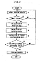
- FIG. 2 shows a basic flow of the fastening operation of the power impact tool in this embodiment.
- the motor controller 9 When the user operates the trigger switch 92, the motor controller 9 outputs a control signal for starting the driving of the motor 1 so as to fasten the fastening member.
- the impact sensor 4 starts to sense the occurrence of the impact of the hammer 2 (S1).
- the rotation angle calculator 60 calculates the rotation angle ⁇ r of the anvil 30 while the hammer 2 impacts the anvil 30 (S3).
- the rotation speed calculator 61 calculates the rotation speed ⁇ of the driving shaft 11 of the motor 1 at the occurrence of the impact (S4).
- the torque estimator 6 calculates the value the estimated torque T according to the above-mentioned equation (S5).
- the fastening judger 7 compares the calculated value of the estimated torque T with the reference value set in the torque setter 8 (S6). When the value of the estimated torque T is smaller than the reference value (Yes in S6), the steps S1 to S6 are executed repeatedly. Alternatively, when the value of the estimated torque T becomes equal to or larger than the reference value (No in S6), the fastening judger 7 executes the stopping process for stopping the driving of the motor 1 (S7).
- FIGS. 3 and 4 respectively show examples of a front view of the torque setter 8.
- the torque setter 8 has a rotary switch, a dial of the rotary switch and a switching circuit connected to the rotary switch for varying a level of an output signal corresponding to an indication position of the rotary switch.
- the values of the torque can be selected among nine levels designated by numerals 1 to 9 and switching off at which the value of torque becomes infinitely grate, corresponding to the position of the dial.
- the torque setter 8 has an LED array serving as an indicator for showing nine levels of the value of the torque, two push switches SWa and SWb and a switching circuit connected to the LEDs and the push switches SWa and SWb for varying a level of an output signal corresponding to pushing times of the push switches SWa and SWb or number of lit LEDs.
- the fastening member is made of a softer material or the size of the fastening member is smaller, the torque necessary for fastening the fastening member is smaller, so that it is preferable to set the reference value of the torque smaller.
- the fastening member is made of harder material or the size of the fastening member is larger, the torque necessary for fastening the fastening member is larger, so that it is preferable to set the reference value of the torque larger. Consequently, it is possible to carry out the fastening operation suitably corresponding to the material or the size of the fastening member.
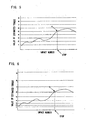
- FIG. 5 shows a relation between the impact number of the hammer 2 and the value of the estimated torque.
- abscissa designates the impact number of the hammer 2
- ordinate designates the value of the estimated torque.
- the reference values of the torque to be compared corresponding to the levels one to nine are set to increase linearly.
- the reference value of the torque is set, for example, to be the level five in FIG. 3 or 4 .
- the value of the estimated torque gradually increases with a little variation.
- the driving of the motor 1 is stopped. Since the value of the estimated torque includes fluctuation not a few, it is preferable to calculate the value of the estimated torque based on a moving average of the impact number.
- FIG. 8 shows a table showing an example of the levels of the reference value of the torque to be compared corresponding to the materials of the component to be fastened by the fastening member and the size of the fastening member. It is assumed that the user sets the first rotary switch SW1 to indicate the woodwork and the second rotary switch SW2 to indicate the size 25 mm. The switching circuit outputs a signal corresponding to the reference value of the torque at the level four.
- the impact energy is generated at the moment when the hammer 2 impacts the anvil 30, it is necessary to measure the speed of the hammer 2 at the moment of the impact for obtaining the impact energy, precisely.
- the hammer 2 moves in the axial direction of the driving shaft 11, and the impulsive force acts on the hammer 2.
- the impact energy is calculated with basing on the average rotation speed of the driving shaft 11 of the motor 1.
- the impact mechanism of the hammer 2 is very complex due to the intervening of the spring 12.
- the function F( ⁇ ) is caused by the impact mechanism, it can be obtained with using the actual tool, experimentally. For example, when the average rotation speed ⁇ is smaller, the value of the function F( ⁇ ) becomes larger.
- the value of the estimated torque T is compensated by the function F( ⁇ ) corresponding to the value of the average rotation speed ⁇ , so that the accuracy of the estimation of the torque for fastening the fastening member can be increased. Consequently, more precise fastening operation of the fastening member can be carried out.
- the relations between the rotation angles ⁇ r of the fastening member and the numbers of pulses in the output signal from the frequency generator 5 become as follows.
- the rotation angles ⁇ r becomes 1.875 degrees per one pulse, 3.75 degrees per two pulses, 5.625 degrees per three pulses, 45 degrees per twenty four pulses, and 90 degrees per fourth eight pulses.
- the torque necessary for fastening the fastening member is much larger.
- the rotation angle ⁇ r of the output shaft 3 is 3 degrees, the number of pulses in the output signal from the frequency generator 5 becomes one or two.
- the value of the estimated torque is calculated by the above-mentioned equation, so that the value of the estimated torque when the number of pulses is one shows double larger than the value of the estimated torque when the number of pulses is two. That is, when the torque necessary for fastening the fastening member is much larger, a large accidental error component occurs in the value of the estimated torque. Consequently, the driving of the motor 1 could be stopped erroneously. If a frequency generator having a very high resolution were used for sensing the rotation angle of the output shaft, such the disadvantage could be solved. The cost of the power impact driver, however, became very expensive.
- the fastening judger 7 of the power impact driver 1 in this embodiment subtracts a number such as 95 or 94 which is smaller than 96 from the number of pulses in the output signal from the frequency generator 5 in consideration of offset value, instead of the number of pulses (96 in the above-mentioned assumption) corresponding to the rotation of the hammer 2 between two impacts.
- the number to be subtracted is selected as 94 (offset value is -2)
- the number of pulses corresponding to the rotation angle 3 degrees becomes three or four.
- the value of the estimated torque corresponding to three pulses becomes about 1.3 times larger than the value of the estimated torque corresponding to four pulses.
- the accidental error component in the value of the estimated torque becomes smaller. It is needless to say that the numerator of the above-mentioned equation for calculating the value of the estimated torque is compensated by multiplying two-fold or three-fold.
- the rotation angle of the output shaft 3 is larger, the accidental error component due to the above-mentioned offset can be tolerated.
- the rotation angle of the output shaft 3 is 90 degrees, the number of pulses in the output signal from the frequency generator 5 becomes 48 without the consideration of the offset, and becomes 50 with the consideration of the offset.
- the motor controller 9 has a speed control function for controlling the rotation speed of the driving shaft 11 of the motor 1 (hereinafter, abbreviated as "rotation speed of the motor 1") corresponding to a stroke of the trigger switch 92.
- FIG. 9 shows a relation between the stroke of the trigger switch 92 and the rotation speed of the motor 1.
- abscissa designates the stroke of the trigger switch 92
- ordinate designates the rotation speed of the motor 1.
- a region from 0 to A of the stroke of the trigger switch 92 corresponds to a play in which the motor 1 is not driven.
- a region from A to B of the stroke of the trigger switch 92 corresponds to the speed control region in which the longer the stroke of the trigger switch 92 becomes, the faster the rotation speed of the motor 1 becomes.
- a region from B to C of the stroke of the trigger switch 92 corresponds to a top rotation speed region in which the motor 1 is driven at the top rotation speed.
- the rotation speed of the motor 1 can be adjusted finely in a low speed.
- a limit is put on the rotation speed of the motor 1 corresponding to the value of the torque level set in the torque setter 8, further to the control of the rotation speed of the motor 1 corresponding to the stroke of the trigger switch 92, as shown in FIG. 10 .
- the lower the torque level set in the torque setter 8 is, the lower the limited top rotation speed of the motor 1 becomes, and the gentler the slope of the characteristic curve of the rotation speed of the motor 1 with respect to the stroke of the trigger switch 92 is made.
- the power impact tool carries out the fastening operation of the fastening member at a high torque, it has an advantage that the time necessary for work operation is shorter. It, however, has a disadvantage that the power is too high to fasten the fastening member made of softer material or smaller, so that the fastening member or the component to be fastened by the fastening member will be damaged by the impact in several times. On the contrary, when the top rotation speed of the motor 1 is limited lower corresponding to the torque necessary for fastening the fastening member, it is possible to reduce the impact energy at the impact of the hammer 2 on the anvil 30.
- the fastening operation can suitably be carried out corresponding to the kind of the materials and/or sizes of the fastening member and the component to be fastened by the fastening member. If there were no impact of the hammer 2 on the anvil 30, it were impossible to estimate the torque for fastening the fastening member.
- the lower limit of the top rotation speed of the motor 1 is defined as the value at which the impact of the hammer 2 on the anvil 30 surely occurs.
- the torque level in the torque setter 8 is automatically set corresponding to the condition that the power impact tool is used. For example, when the torque level is initially set as level four, and the motor 1 is driven by switching on the trigger switch 92, the driving of the motor 1 is stopped when the calculated value of the estimated torque reaches to the value corresponding to the level four.
- the trigger switch 92 is further switched on in a predetermined term (for example, one second)
- the fastening judger 7 shifts the torque level one step to level five, and restarts to drive the motor 1, and stops the driving of the motor 1 when the calculated value of the estimated torque reaches to the value corresponding to the level five.
- the fastening judger 7 shifts the torque level one step by one, and restarts to drive the motor 1.
- the torque level reaches to the highest, the fastening judger 7 continues to drive the motor 1 at the highest torque level.
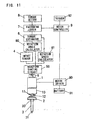
- FIG. 11 shows another configuration of the power impact tool in this embodiment.
- the output signal from the frequency generator 5 is inputted to the impact sensor 4 via the waveform shaping circuit 50.
- the frequency generator 5 is used not only as a part of the rotation speed sensor, but also as a part of the impact sensor instead of the microphone 40. Specifically, the rotation speed of the motor 1 is reduced a little due to load fluctuation when the hammer 2 impacts the anvil 30, and the pulse width of the frequency signal outputted from the frequency generator 5 becomes a little wider.
- the impact sensor 4 senses the variation of the pulse width of the frequency signal as the occurrence of the impact. Furthermore, it is possible to use an acceleration sensor for sensing the occurrence of the impact of the hammer 2 on the anvil 30.
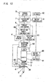
- FIG. 12 shows still another example of a configuration of the power impact tool in this embodiment.
- the power impact tool further comprises a rotary encoder 41 serving as a rotation angle sensor for sensing the rotation angle of the output shaft 3, directly.
- a rotary encoder 41 serving as a rotation angle sensor for sensing the rotation angle of the output shaft 3, directly.
- the motor 1 is used as a driving power source.
- the present invention is not limited the description or drawing of the embodiment. It is possible to use another driving source such as a compressed air, or the like.
Landscapes
- Engineering & Computer Science (AREA)
- Mechanical Engineering (AREA)
- Details Of Spanners, Wrenches, And Screw Drivers And Accessories (AREA)
- Mechanical Pencils And Projecting And Retracting Systems Therefor, And Multi-System Writing Instruments (AREA)
- Percussive Tools And Related Accessories (AREA)
Claims (9)
- Kraftgetriebenes Schlagwerkzeug mit:einem Hammer (2);einem Antriebsmechanismus, der einen Motor (1) und eine Antriebswelle (11) für den Drehantrieb des Hammers (2) um die Antriebswelle (11) einschließt;einer Ausgangswelle (3), auf die eine Drehantriebskraft auf Grund eines Aufpralls des Hammers (2) aufgebracht wird;einem Aufprall-Sensor (4, 40) zum Messen des Auftretens des Aufpralls des Hammers (2);einem Drehgeschwindigkeits-Sensor (5) zum Messen einer Drehgeschwindigkeit der Antriebswelle (11) unter Verwendung eines Drehwinkels der Antriebswelle (11);einem Drehwinkel-Sensor (5, 41) zum Messen eines Drehwinkels der Angangswelle (11) in einem Zeitraum von einer Zeit, zu der der Aufprall-Sensor (4, 40) das Auftreten eines Aufpralls des Hammers (2) misst, zu einer weiteren Zeit, zu der der Aufprall-Sensor das nächste Auftreten des Aufpralls des Hammers misst;einer Drehmoment-Schätzeinrichtung (6) zum Berechnen einer Aufprall-Energie unter Verwendung einer mittleren Drehgeschwindigkeit der Antriebswelle (11), die von dem Drehgeschwindigkeits-Sensor (5) gemessen wird, und zur Berechnung eines Wertes des geschätzten Drehmomentes zum Festziehen eines Befestigungselementes, der als eine Division der Aufprall-Energie durch den Drehwinkel der Ausgangswelle (11) gegeben ist;einer Drehmoment-Einstelleinrichtung (8) zum Einstellen eines zu vergleichenden Bezugswertes des Drehmomentes; undeiner Steuereinrichtung (9) zum Stoppen der Drehung der Antriebswelle (11), wenn der Wert des geschätzten Drehmomentes gleich oder größer als ein vorgegebener Bezugswert wird, der durch die Drehmoment-Einstelleinrichtung (8) eingestellt ist, und die eine Drehzahlsteuerfunktion zum Steuern der Drehgeschwindigkeit der Antriebswelle (11) entsprechend einem Hub eines Abzugschalters (92) aufweist, dadurch gekennzeichnet, dasseine Begrenzung der Drehgeschwindigkeit des Motors (1) entsprechend dem Wert des Drehmoment-Pegels auferlegt ist, der in der Drehmoment-Einstelleinrichtung (8) eingestellt ist, so dass die begrenzte höchste Drehgeschwindigkeit des Motors (1) um so niedriger wird, und die Steigung der charakteristischen Kurve der Drehgeschwindigkeit des Motors (1) gegenüber dem Hub des Abzugschalters (92) um so sanfter gemacht ist, je niedriger der in der Drehmoment-Einstelleinrichtung (8) eingestellte Drehmoment-Pegel ist.
- Kraftgetriebenes Schlagwerkzeug nach Anspruch 1, bei dem:der Drehwinkel-Sensor den Drehwinkel der Ausgangswelle unter Verwendung des Drehwinkels der Antriebswelle berechnet, die von dem Drehwinkel-Sensor gemessen wird.
- Kraftgetriebenes Schlagwerkzeug nach Anspruch 1, bei dem:die Drehmoment-Schätzeinrichtung den Wert der Schlag-Energie entsprechend dem Wert der mittleren Drehgeschwindigkeit der Antriebswelle kompensiert, wenn die Aufprall-Energie unter Verwendung der mittleren Drehgeschwindigkeit berechnet wird.
- Kraftgetriebenes Schlagwerkzeug nach Anspruch 1, bei dem:die Drehmoment-Schätzeinrichtung einen vorgegebenen Offset-Wert zu dem Wert des von dem Drehwinkel-Sensor gemessenen Drehwinkels hinzu addiert, wenn der Wert des geschätzten Drehmomentes berechnet wird.
- Kraftgetriebenes Schlagwerkzeug nach Anspruch 1, bei dem:die Drehmoment-Einstelleinrichtung eine Mehrzahl von Pegeln der Bezugswerte aufweist, die von einem Benutzer ausgewählt werden, und die Bezugswerte nichtlinear in einer Weise derart vergrößert werden, dass der Anstieg des Wertes um so größer wird, je höher der Pegel wird.
- Kraftgetriebenes Schlagwerkzeug nach Anspruch 1, bei dem:die Drehmoment-Einstelleinrichtung eine Größen-Wähleinrichtung zum Wählen einer Größe des Befestigungselementes aus einer Mehrzahl von Größen, die vorher eingestellt wurden, und eine Art-Auswahleinrichtung zur Auswahl einer Art eines durch das Befestigungselement zu befestigende Komponente aus einer Mehrzahl von vorher ausgewählten Arten aufweist, und das der Bezugswert aus einer Mehrzahl von Werten entsprechend einer Kombination der Größe des Befestigungselementes und der Art der zu befestigenden Komponente ausgewählt wird.
- Kraftgetriebenes Schlagwerkzeug nach Anspruch 1, bei dem:weiterhin ein Abzugschalter zum Ein- und Ausschalten der Drehung der Antriebswelle des Antriebsmechanismus und zum Ändern der Drehgeschwindigkeit der Antriebswelle entsprechend eines Hubes des durch einen Benutzer betätigten Abzugschalters vorgesehen ist; unddie Steuereinrichtung eine Begrenzung für die Drehgeschwindigkeit der Antriebswelle des Antriebsmechanismus ohne Beziehung zu einem Hub des Abzugschalters auferlegt, wenn der in der Drehmoment-Einstelleinrichtung eingestellte Bezugswert kleiner als ein vorgegebener Pegel ist.
- Kraftgetriebenes Schlagwerkzeug nach Anspruch 7, bei dem:die Begrenzung der Drehgeschwindigkeit der Antriebswelle schneller als eine untere Grenze ist, bei der ein Aufprall des Hammers erfolgen kann.
- Kraftgetriebenes Schlagwerkzeug nach Anspruch 1, bei dem das kraftgetriebene Schlagwerkzeug weiterhin Folgendes einschließt:einen Abzugschalter (92), der zum Einschalten und Ausschalten der Drehung der Antriebswelle (11) des Antriebsmechanismus und zum Ändern der Drehgeschwindigkeit der Antriebswelle (11) entsprechend einem Hub des durch einen Benutzer betätigten Abzugschalters vorgesehen ist; unddie Steuereinrichtung (9) den Antrieb des Antriebsmechanismus (1, 11) stoppt, wenn der von der Drehmoment-Schutzeinrichtung berechnete Wert des geschätzten Drehmomentes gleich oder größer als der in der Drehmoment-Einstelleinrichtung eingestellte Bezugswert wird, und den Antrieb des Antriebsmechanismus (1, 11) beim Verschieben des Drehmoment-Pegels um einen Schritt höher neu startet, wenn der Abzugschalter (92) weiterhin in einer vorgegebenen Zeit nach dem Stoppen des Antriebs des Antriebsmechanismus (1, 11) eingeschaltet ist.
Applications Claiming Priority (2)
| Application Number | Priority Date | Filing Date | Title |
|---|---|---|---|
| JP2003354197 | 2003-10-14 | ||
| JP2003354197A JP2005118910A (ja) | 2003-10-14 | 2003-10-14 | インパクト回転工具 |
Publications (3)
| Publication Number | Publication Date |
|---|---|
| EP1524084A2 EP1524084A2 (de) | 2005-04-20 |
| EP1524084A3 EP1524084A3 (de) | 2006-08-16 |
| EP1524084B1 true EP1524084B1 (de) | 2009-08-19 |
Family
ID=34373557
Family Applications (1)
| Application Number | Title | Priority Date | Filing Date |
|---|---|---|---|
| EP04256316A Expired - Lifetime EP1524084B1 (de) | 2003-10-14 | 2004-10-14 | Angetriebenes Schlagwerkzeug |
Country Status (6)
| Country | Link |
|---|---|
| US (1) | US6945337B2 (de) |
| EP (1) | EP1524084B1 (de) |
| JP (1) | JP2005118910A (de) |
| CN (1) | CN1283419C (de) |
| AT (1) | ATE439948T1 (de) |
| DE (1) | DE602004022621D1 (de) |
Cited By (9)
| Publication number | Priority date | Publication date | Assignee | Title |
|---|---|---|---|---|
| US8286723B2 (en) | 2010-01-07 | 2012-10-16 | Black & Decker Inc. | Power screwdriver having rotary input control |
| US8418778B2 (en) | 2010-01-07 | 2013-04-16 | Black & Decker Inc. | Power screwdriver having rotary input control |
| USRE44311E1 (en) | 2004-10-20 | 2013-06-25 | Black & Decker Inc. | Power tool anti-kickback system with rotational rate sensor |
| US10052733B2 (en) | 2015-06-05 | 2018-08-21 | Ingersoll-Rand Company | Lighting systems for power tools |
| US10418879B2 (en) | 2015-06-05 | 2019-09-17 | Ingersoll-Rand Company | Power tool user interfaces |
| US10615670B2 (en) | 2015-06-05 | 2020-04-07 | Ingersoll-Rand Industrial U.S., Inc. | Power tool user interfaces |
| US10668614B2 (en) | 2015-06-05 | 2020-06-02 | Ingersoll-Rand Industrial U.S., Inc. | Impact tools with ring gear alignment features |
| US11260517B2 (en) | 2015-06-05 | 2022-03-01 | Ingersoll-Rand Industrial U.S., Inc. | Power tool housings |
| US11491616B2 (en) | 2015-06-05 | 2022-11-08 | Ingersoll-Rand Industrial U.S., Inc. | Power tools with user-selectable operational modes |
Families Citing this family (90)
| Publication number | Priority date | Publication date | Assignee | Title |
|---|---|---|---|---|
| JP4329369B2 (ja) | 2003-03-20 | 2009-09-09 | パナソニック電工株式会社 | 電動工具の使用支援方法及びその装置 |
| JP4400303B2 (ja) * | 2004-05-12 | 2010-01-20 | パナソニック電工株式会社 | インパクト回転工具 |
| JP4211676B2 (ja) * | 2004-05-12 | 2009-01-21 | パナソニック電工株式会社 | インパクト回転工具 |
| JP4211675B2 (ja) * | 2004-05-12 | 2009-01-21 | パナソニック電工株式会社 | インパクト回転工具 |
| US7410006B2 (en) | 2004-10-20 | 2008-08-12 | Black & Decker Inc. | Power tool anti-kickback system with rotational rate sensor |
| GB2435189B (en) * | 2004-12-17 | 2010-06-23 | Milwaukee Electric Tool Corp | Saw and Blade with Operational Communication |
| JP4211744B2 (ja) * | 2005-02-23 | 2009-01-21 | パナソニック電工株式会社 | インパクト締付け工具 |
| WO2007025322A1 (en) * | 2005-08-29 | 2007-03-08 | Demain Technology Pty Ltd | Power tool |
| DE602006015970D1 (de) * | 2005-08-29 | 2010-09-16 | Demain Technology Pty Ltd | Kraftbetriebenes Werkzeug |
| US7565844B2 (en) * | 2005-11-28 | 2009-07-28 | Snap-On Incorporated | Torque-angle instrument |
| WO2007106952A1 (en) * | 2006-03-23 | 2007-09-27 | Demain Technology Pty Ltd | A power tool guard |
| US20080021590A1 (en) * | 2006-07-21 | 2008-01-24 | Vanko John C | Adaptive control scheme for detecting and preventing torque conditions in a power tool |
| JP2008055563A (ja) * | 2006-08-31 | 2008-03-13 | Matsushita Electric Works Ltd | 電動工具 |
| DE102007019409B3 (de) * | 2007-04-23 | 2008-11-13 | Lösomat Schraubtechnik Neef Gmbh | Kraftschrauber |
| SE532128C2 (sv) * | 2008-02-20 | 2009-10-27 | Atlas Copco Tools Ab | Mutterdragare med en kraftöverförande växel och rotationsavkännande organ, samt metod för fastställande växelns status |
| JP5126515B2 (ja) * | 2008-05-08 | 2013-01-23 | 日立工機株式会社 | オイルパルス工具 |
| US8269612B2 (en) | 2008-07-10 | 2012-09-18 | Black & Decker Inc. | Communication protocol for remotely controlled laser devices |
| GB2474221B (en) * | 2008-08-06 | 2012-12-12 | Milwaukee Electric Tool Corp | Precision torque tool |
| JP5405157B2 (ja) * | 2009-03-10 | 2014-02-05 | 株式会社マキタ | 回転打撃工具 |
| DE102009002479B4 (de) * | 2009-04-20 | 2015-02-19 | Hilti Aktiengesellschaft | Schlagschrauber und Steuerungsverfahren für einen Schlagschrauber |
| US9266178B2 (en) | 2010-01-07 | 2016-02-23 | Black & Decker Inc. | Power tool having rotary input control |
| US9475180B2 (en) | 2010-01-07 | 2016-10-25 | Black & Decker Inc. | Power tool having rotary input control |
| JP5483089B2 (ja) * | 2010-03-11 | 2014-05-07 | 日立工機株式会社 | インパクト工具 |
| JP5900782B2 (ja) * | 2010-04-30 | 2016-04-06 | 日立工機株式会社 | 電動工具 |
| JP5486435B2 (ja) * | 2010-08-17 | 2014-05-07 | パナソニック株式会社 | インパクト回転工具 |
| EP2635410B1 (de) | 2010-11-04 | 2016-10-12 | Milwaukee Electric Tool Corporation | Schlagwerkzeug mit einstellbarer kupplung |
| DE102010063173A1 (de) * | 2010-12-15 | 2012-06-21 | Hilti Aktiengesellschaft | Bolzensetzgerät und Verfahren zum Betreiben eines Bolzensetzgerätes |
| JP5755988B2 (ja) * | 2011-09-30 | 2015-07-29 | 株式会社マキタ | 電動工具 |
| JP5784473B2 (ja) * | 2011-11-30 | 2015-09-24 | 株式会社マキタ | 回転打撃工具 |
| US9908182B2 (en) | 2012-01-30 | 2018-03-06 | Black & Decker Inc. | Remote programming of a power tool |
| EP2631035B1 (de) | 2012-02-24 | 2019-10-16 | Black & Decker Inc. | Elektrisches Werkzeug |
| CN103286727B (zh) * | 2012-03-02 | 2015-06-10 | 南京德朔实业有限公司 | 可调节扭力的冲击扳手 |
| JP2013184266A (ja) * | 2012-03-09 | 2013-09-19 | Hitachi Koki Co Ltd | 電動工具及び電動工具システム |
| US9193055B2 (en) | 2012-04-13 | 2015-11-24 | Black & Decker Inc. | Electronic clutch for power tool |
| DE102012208902A1 (de) * | 2012-05-25 | 2013-11-28 | Robert Bosch Gmbh | Schlagwerkeinheit |
| US8919456B2 (en) | 2012-06-08 | 2014-12-30 | Black & Decker Inc. | Fastener setting algorithm for drill driver |
| US20130327552A1 (en) * | 2012-06-08 | 2013-12-12 | Black & Decker Inc. | Power tool having multiple operating modes |
| US20140110138A1 (en) * | 2012-10-23 | 2014-04-24 | David Zarrin | Protective apparatus in connection with machine tools to safeguard workload installation |
| CN104175267B (zh) * | 2013-05-20 | 2016-08-03 | 南京德朔实业有限公司 | 电动工具及其控制方法 |
| US9701000B2 (en) | 2013-07-19 | 2017-07-11 | Panasonic Intellectual Property Management Co., Ltd. | Impact rotation tool and impact rotation tool attachment |
| US20150041162A1 (en) * | 2013-08-06 | 2015-02-12 | China Pneumatic Corporation | Programmable torque control method for sensing locking element |
| US9597784B2 (en) | 2013-08-12 | 2017-03-21 | Ingersoll-Rand Company | Impact tools |
| WO2015061370A1 (en) | 2013-10-21 | 2015-04-30 | Milwaukee Electric Tool Corporation | Adapter for power tool devices |
| DE102013224759A1 (de) * | 2013-12-03 | 2015-06-03 | Robert Bosch Gmbh | Werkzeugmaschinenvorrichtung |
| JP6380924B2 (ja) * | 2014-01-06 | 2018-08-29 | パナソニックIpマネジメント株式会社 | インパクト回転工具の慣性モーメントの測定方法とその測定方法を用いたインパクト回転工具 |
| US9539715B2 (en) | 2014-01-16 | 2017-01-10 | Ingersoll-Rand Company | Controlled pivot impact tools |
| CN103753467A (zh) * | 2014-01-25 | 2014-04-30 | 浙江立邦电器有限公司 | 一种电扳手 |
| JP6304533B2 (ja) * | 2014-03-04 | 2018-04-04 | パナソニックIpマネジメント株式会社 | インパクト回転工具 |
| JP6399437B2 (ja) * | 2014-06-04 | 2018-10-03 | パナソニックIpマネジメント株式会社 | 制御装置及びそれを用いた作業管理システム |
| DE102015211119A1 (de) * | 2014-06-20 | 2015-12-24 | Robert Bosch Gmbh | Verfahren zum Steuern eines Elektromotors eines Elektrowerkzeuges |
| SE538622C2 (sv) * | 2015-04-02 | 2016-10-04 | Atlas Copco Ind Technique Ab | Power tool with output torque compensation and method therefore |
| US10603770B2 (en) * | 2015-05-04 | 2020-03-31 | Milwaukee Electric Tool Corporation | Adaptive impact blow detection |
| US10295990B2 (en) | 2015-05-18 | 2019-05-21 | Milwaukee Electric Tool Corporation | User interface for tool configuration and data capture |
| EP4029652A1 (de) * | 2015-06-02 | 2022-07-20 | Milwaukee Electric Tool Corporation | Elektrowerkzeug mit mehreren geschwindigkeiten mit elektronischer kupplung |
| KR102251270B1 (ko) | 2016-01-05 | 2021-05-11 | 밀워키 일렉트릭 툴 코포레이션 | 전동 공구를 위한 진동 감소 시스템 및 그 방법 |
| JP6558737B2 (ja) | 2016-01-29 | 2019-08-14 | パナソニックIpマネジメント株式会社 | インパクト回転工具 |
| JP6608540B2 (ja) | 2016-02-03 | 2019-11-20 | ミルウォーキー エレクトリック ツール コーポレイション | レシプロソーを設定するシステム及び方法 |
| AU2017223863B2 (en) | 2016-02-25 | 2019-12-19 | Milwaukee Electric Tool Corporation | Power tool including an output position sensor |
| JP6764255B2 (ja) * | 2016-05-18 | 2020-09-30 | 株式会社マキタ | 電動作業機 |
| US10589413B2 (en) | 2016-06-20 | 2020-03-17 | Black & Decker Inc. | Power tool with anti-kickback control system |
| CN105922184A (zh) * | 2016-06-25 | 2016-09-07 | 中铁电气化局集团有限公司 | 高铁电动定扭矩扳手 |
| JP6868851B2 (ja) | 2017-01-31 | 2021-05-12 | パナソニックIpマネジメント株式会社 | インパクト回転工具 |
| JP6814979B2 (ja) | 2017-02-24 | 2021-01-20 | パナソニックIpマネジメント株式会社 | 電動工具 |
| JP6811130B2 (ja) * | 2017-03-23 | 2021-01-13 | 株式会社マキタ | インパクト締結工具 |
| KR102429488B1 (ko) * | 2017-06-08 | 2022-08-05 | 현대자동차주식회사 | 토크 제한 장치, 그를 포함한 전동 드라이버, 및 그 방법 |
| JP6901346B2 (ja) | 2017-08-09 | 2021-07-14 | 株式会社マキタ | 電動作業機 |
| JP6916060B2 (ja) * | 2017-08-09 | 2021-08-11 | 株式会社マキタ | 電動作業機 |
| CN111051006B (zh) * | 2017-08-29 | 2021-11-30 | 松下知识产权经营株式会社 | 信号处理装置和工具 |
| JP6868808B2 (ja) | 2017-09-26 | 2021-05-12 | パナソニックIpマネジメント株式会社 | 電動工具 |
| JP6913870B2 (ja) * | 2017-10-30 | 2021-08-04 | パナソニックIpマネジメント株式会社 | インパクト回転工具 |
| EP3501740A1 (de) * | 2017-12-20 | 2019-06-26 | HILTI Aktiengesellschaft | Setzverfahren für schraubverbindung mittels schlagschrauber |
| US10835972B2 (en) | 2018-03-16 | 2020-11-17 | Milwaukee Electric Tool Corporation | Blade clamp for power tool |
| USD887806S1 (en) | 2018-04-03 | 2020-06-23 | Milwaukee Electric Tool Corporation | Jigsaw |
| WO2019194987A1 (en) | 2018-04-03 | 2019-10-10 | Milwaukee Electric Tool Corporation | Jigsaw |
| JP6941776B2 (ja) | 2018-04-25 | 2021-09-29 | パナソニックIpマネジメント株式会社 | 電動工具 |
| WO2020057953A1 (en) * | 2018-09-21 | 2020-03-26 | Atlas Copco Industrial Technique Ab | Electric pulse tool |
| CN109909938B (zh) * | 2019-03-25 | 2024-06-21 | 北京弘益鼎视科技发展有限公司 | 冲击扳手 |
| JP7426060B2 (ja) * | 2019-06-03 | 2024-02-01 | 三洋機工株式会社 | ナットランナおよびねじ締付方法 |
| CN110614531A (zh) * | 2019-09-19 | 2019-12-27 | 云南机电职业技术学院 | 五轴数控机床的实时防碰撞装置 |
| JP7386027B2 (ja) * | 2019-09-27 | 2023-11-24 | 株式会社マキタ | 回転打撃工具 |
| JP7320419B2 (ja) | 2019-09-27 | 2023-08-03 | 株式会社マキタ | 回転打撃工具 |
| JP7178591B2 (ja) * | 2019-11-15 | 2022-11-28 | パナソニックIpマネジメント株式会社 | インパクト工具、インパクト工具の制御方法及びプログラム |
| EP3825067A1 (de) * | 2019-11-21 | 2021-05-26 | Hilti Aktiengesellschaft | Verfahren zum betreiben einer werkzeugmaschine und werkzeugmaschine |
| CN111843454A (zh) * | 2020-04-27 | 2020-10-30 | 海安迪斯凯瑞探测仪器有限公司 | 具有扭矩和转角监测控制功能的合模用螺丝锁紧治具 |
| WO2021222729A1 (en) * | 2020-05-01 | 2021-11-04 | Milwaukee Electric Tool Corporation | Rotary impact tool |
| US20250128387A1 (en) * | 2020-10-07 | 2025-04-24 | Ingersoll-Rand Industrial U.S., Inc. | Torque control tool |
| EP4263138A1 (de) | 2020-12-18 | 2023-10-25 | Black & Decker Inc. | Schlagwerkzeuge und steuerungsmodi |
| JP7727501B2 (ja) * | 2021-11-19 | 2025-08-21 | パナソニックホールディングス株式会社 | インパクト回転工具、インパクト回転工具システム、管理システム |
| JP2025171813A (ja) * | 2024-05-10 | 2025-11-20 | パナソニック株式会社 | インパクト回転工具 |
| US12465385B1 (en) * | 2025-04-29 | 2025-11-11 | Dixing Chen | Foot repair device |
Family Cites Families (16)
| Publication number | Priority date | Publication date | Assignee | Title |
|---|---|---|---|---|
| US4316512A (en) * | 1979-04-04 | 1982-02-23 | Sps Technologies, Inc. | Impact wrench |
| JPH04322974A (ja) | 1991-04-22 | 1992-11-12 | Nhk Spring Co Ltd | インパクトレンチ |
| JP2943457B2 (ja) * | 1991-09-30 | 1999-08-30 | トヨタ自動車株式会社 | ナットランナ |
| JPH0691551A (ja) | 1992-09-07 | 1994-04-05 | Nissan Motor Co Ltd | インパクト式ねじ締め装置 |
| DE4243069C2 (de) * | 1992-12-18 | 2001-09-27 | Gardner Denver Gmbh | Impulswerkzeug, insbesondere Impulsschrauber |
| US5402688A (en) * | 1993-03-17 | 1995-04-04 | Sumitomo Metal Industries, Ltd. | Method and apparatus for determining the tightened condition of a pipe joint |
| JP3000185B2 (ja) * | 1993-04-21 | 2000-01-17 | 株式会社山崎歯車製作所 | インパクトレンチによるボルト締結方法 |
| JPH07100772A (ja) * | 1993-10-01 | 1995-04-18 | Ricoh Co Ltd | 回転式動力工具 |
| JP3373622B2 (ja) * | 1993-10-26 | 2003-02-04 | 松下電工株式会社 | インパクトレンチ |
| DE4402739C2 (de) * | 1994-01-28 | 1996-06-20 | Volkswagen Ag | Impulsschrauber |
| JPH09285974A (ja) | 1996-04-18 | 1997-11-04 | Yamazaki Haguruma Seisakusho:Kk | インパクトレンチの締付制御方法とその装置 |
| DE19647813C2 (de) * | 1996-11-19 | 2003-07-03 | Joerg Hohmann | Kraftschrauber |
| JP3906606B2 (ja) * | 1999-06-11 | 2007-04-18 | 松下電工株式会社 | インパクト回転工具 |
| WO2001044776A1 (en) * | 1999-12-16 | 2001-06-21 | Magna-Lastic Devices, Inc. | Impact tool control method and apparatus and impact tool using the same |
| EP1982798A3 (de) * | 2000-03-16 | 2008-11-12 | Makita Corporation | Elektrowerkzeug |
| JP2001277146A (ja) | 2000-03-31 | 2001-10-09 | Matsushita Electric Works Ltd | 動力駆動回転工具 |
-
2003
- 2003-10-14 JP JP2003354197A patent/JP2005118910A/ja active Pending
-
2004
- 2004-10-13 US US10/962,565 patent/US6945337B2/en not_active Expired - Lifetime
- 2004-10-14 AT AT04256316T patent/ATE439948T1/de not_active IP Right Cessation
- 2004-10-14 DE DE602004022621T patent/DE602004022621D1/de not_active Expired - Lifetime
- 2004-10-14 CN CN200410088135.4A patent/CN1283419C/zh not_active Expired - Lifetime
- 2004-10-14 EP EP04256316A patent/EP1524084B1/de not_active Expired - Lifetime
Cited By (14)
| Publication number | Priority date | Publication date | Assignee | Title |
|---|---|---|---|---|
| USRE44311E1 (en) | 2004-10-20 | 2013-06-25 | Black & Decker Inc. | Power tool anti-kickback system with rotational rate sensor |
| USRE44993E1 (en) | 2004-10-20 | 2014-07-08 | Black & Decker Inc. | Power tool anti-kickback system with rotational rate sensor |
| USRE45112E1 (en) | 2004-10-20 | 2014-09-09 | Black & Decker Inc. | Power tool anti-kickback system with rotational rate sensor |
| US8286723B2 (en) | 2010-01-07 | 2012-10-16 | Black & Decker Inc. | Power screwdriver having rotary input control |
| US8418778B2 (en) | 2010-01-07 | 2013-04-16 | Black & Decker Inc. | Power screwdriver having rotary input control |
| US10418879B2 (en) | 2015-06-05 | 2019-09-17 | Ingersoll-Rand Company | Power tool user interfaces |
| US10052733B2 (en) | 2015-06-05 | 2018-08-21 | Ingersoll-Rand Company | Lighting systems for power tools |
| US10615670B2 (en) | 2015-06-05 | 2020-04-07 | Ingersoll-Rand Industrial U.S., Inc. | Power tool user interfaces |
| US10668614B2 (en) | 2015-06-05 | 2020-06-02 | Ingersoll-Rand Industrial U.S., Inc. | Impact tools with ring gear alignment features |
| US11260517B2 (en) | 2015-06-05 | 2022-03-01 | Ingersoll-Rand Industrial U.S., Inc. | Power tool housings |
| US11491616B2 (en) | 2015-06-05 | 2022-11-08 | Ingersoll-Rand Industrial U.S., Inc. | Power tools with user-selectable operational modes |
| US11602832B2 (en) | 2015-06-05 | 2023-03-14 | Ingersoll-Rand Industrial U.S., Inc. | Impact tools with ring gear alignment features |
| US11707831B2 (en) | 2015-06-05 | 2023-07-25 | Ingersoll-Rand Industrial U.S., Inc. | Power tool housings |
| US11784538B2 (en) | 2015-06-05 | 2023-10-10 | Ingersoll-Rand Industrial U.S., Inc. | Power tool user interfaces |
Also Published As
| Publication number | Publication date |
|---|---|
| DE602004022621D1 (de) | 2009-10-01 |
| US20050109519A1 (en) | 2005-05-26 |
| EP1524084A2 (de) | 2005-04-20 |
| CN1283419C (zh) | 2006-11-08 |
| CN1607075A (zh) | 2005-04-20 |
| ATE439948T1 (de) | 2009-09-15 |
| EP1524084A3 (de) | 2006-08-16 |
| US6945337B2 (en) | 2005-09-20 |
| JP2005118910A (ja) | 2005-05-12 |
Similar Documents
| Publication | Publication Date | Title |
|---|---|---|
| EP1524084B1 (de) | Angetriebenes Schlagwerkzeug | |
| EP1524085B1 (de) | Kraftbetriebenes Schraubgerät | |
| EP1595650B1 (de) | Drehschlag-Werkzeug | |
| US6978846B2 (en) | Power tool used for fastening screw or bolt | |
| EP1595651B1 (de) | Drehschlag-Werkzeug | |
| EP1595649B1 (de) | Drehschlag-Werkzeug | |
| EP1447177B1 (de) | Kraftgetriebenes Werkzeug mit Drehmomentbegrenzung unter ausschliesslicher Benutzung eines Drehwinkelsensors | |
| EP1510299B1 (de) | Elektrowerkzeug mit mehreren Betriebsarten | |
| EP1207016B1 (de) | Schlagwerkzeug | |
| US20080289839A1 (en) | Method of controlling a screwdriving power tool | |
| WO2016196984A1 (en) | Power tools with user-selectable operational modes | |
| KR102102106B1 (ko) | 나사 결합 부재 체결 공구 및 나사 결합 부재 체결 공구에 있어서의 구동 시간 설정 방법 | |
| EP3302882B1 (de) | Elektrowerkzeuge mit benutzerwählbaren betriebsmodi | |
| US11701758B2 (en) | Portable power tool | |
| JP2006015438A (ja) | インパクト締め付け工具 | |
| US20240091914A1 (en) | Electric power tool, and method for controlling motor in electric power tool | |
| US20230278185A1 (en) | Electronic clutch for power tool | |
| JP2005006384A (ja) | 電動工具用スイッチおよび同スイッチを用いた電動工具 | |
| EP2724822B1 (de) | Kraftgetriebenes Handwerkzeug |
Legal Events
| Date | Code | Title | Description |
|---|---|---|---|
| PUAI | Public reference made under article 153(3) epc to a published international application that has entered the european phase |
Free format text: ORIGINAL CODE: 0009012 |
|
| AK | Designated contracting states |
Kind code of ref document: A2 Designated state(s): AT BE BG CH CY CZ DE DK EE ES FI FR GB GR HU IE IT LI LU MC NL PL PT RO SE SI SK TR |
|
| AX | Request for extension of the european patent |
Extension state: AL HR LT LV MK |
|
| PUAL | Search report despatched |
Free format text: ORIGINAL CODE: 0009013 |
|
| AK | Designated contracting states |
Kind code of ref document: A3 Designated state(s): AT BE BG CH CY CZ DE DK EE ES FI FR GB GR HU IE IT LI LU MC NL PL PT RO SE SI SK TR |
|
| AX | Request for extension of the european patent |
Extension state: AL HR LT LV MK |
|
| 17P | Request for examination filed |
Effective date: 20061009 |
|
| 17Q | First examination report despatched |
Effective date: 20070112 |
|
| AKX | Designation fees paid |
Designated state(s): AT BE BG CH CY CZ DE DK EE ES FI FR GB GR HU IE IT LI LU MC NL PL PT RO SE SI SK TR |
|
| RAP1 | Party data changed (applicant data changed or rights of an application transferred) |
Owner name: PANASONIC ELECTRIC WORKS CO., LTD. |
|
| GRAP | Despatch of communication of intention to grant a patent |
Free format text: ORIGINAL CODE: EPIDOSNIGR1 |
|
| GRAS | Grant fee paid |
Free format text: ORIGINAL CODE: EPIDOSNIGR3 |
|
| GRAA | (expected) grant |
Free format text: ORIGINAL CODE: 0009210 |
|
| AK | Designated contracting states |
Kind code of ref document: B1 Designated state(s): AT BE BG CH CY CZ DE DK EE ES FI FR GB GR HU IE IT LI LU MC NL PL PT RO SE SI SK TR |
|
| REG | Reference to a national code |
Ref country code: GB Ref legal event code: FG4D |
|
| REG | Reference to a national code |
Ref country code: CH Ref legal event code: EP |
|
| REG | Reference to a national code |
Ref country code: IE Ref legal event code: FG4D |
|
| REF | Corresponds to: |
Ref document number: 602004022621 Country of ref document: DE Date of ref document: 20091001 Kind code of ref document: P |
|
| PG25 | Lapsed in a contracting state [announced via postgrant information from national office to epo] |
Ref country code: SE Free format text: LAPSE BECAUSE OF FAILURE TO SUBMIT A TRANSLATION OF THE DESCRIPTION OR TO PAY THE FEE WITHIN THE PRESCRIBED TIME-LIMIT Effective date: 20090819 Ref country code: ES Free format text: LAPSE BECAUSE OF FAILURE TO SUBMIT A TRANSLATION OF THE DESCRIPTION OR TO PAY THE FEE WITHIN THE PRESCRIBED TIME-LIMIT Effective date: 20091130 Ref country code: FI Free format text: LAPSE BECAUSE OF FAILURE TO SUBMIT A TRANSLATION OF THE DESCRIPTION OR TO PAY THE FEE WITHIN THE PRESCRIBED TIME-LIMIT Effective date: 20090819 Ref country code: AT Free format text: LAPSE BECAUSE OF FAILURE TO SUBMIT A TRANSLATION OF THE DESCRIPTION OR TO PAY THE FEE WITHIN THE PRESCRIBED TIME-LIMIT Effective date: 20090819 |
|
| NLV1 | Nl: lapsed or annulled due to failure to fulfill the requirements of art. 29p and 29m of the patents act | ||
| PG25 | Lapsed in a contracting state [announced via postgrant information from national office to epo] |
Ref country code: NL Free format text: LAPSE BECAUSE OF FAILURE TO SUBMIT A TRANSLATION OF THE DESCRIPTION OR TO PAY THE FEE WITHIN THE PRESCRIBED TIME-LIMIT Effective date: 20090819 Ref country code: PL Free format text: LAPSE BECAUSE OF FAILURE TO SUBMIT A TRANSLATION OF THE DESCRIPTION OR TO PAY THE FEE WITHIN THE PRESCRIBED TIME-LIMIT Effective date: 20090819 Ref country code: SI Free format text: LAPSE BECAUSE OF FAILURE TO SUBMIT A TRANSLATION OF THE DESCRIPTION OR TO PAY THE FEE WITHIN THE PRESCRIBED TIME-LIMIT Effective date: 20090819 |
|
| PG25 | Lapsed in a contracting state [announced via postgrant information from national office to epo] |
Ref country code: CY Free format text: LAPSE BECAUSE OF FAILURE TO SUBMIT A TRANSLATION OF THE DESCRIPTION OR TO PAY THE FEE WITHIN THE PRESCRIBED TIME-LIMIT Effective date: 20090819 Ref country code: PT Free format text: LAPSE BECAUSE OF FAILURE TO SUBMIT A TRANSLATION OF THE DESCRIPTION OR TO PAY THE FEE WITHIN THE PRESCRIBED TIME-LIMIT Effective date: 20091221 Ref country code: BG Free format text: LAPSE BECAUSE OF FAILURE TO SUBMIT A TRANSLATION OF THE DESCRIPTION OR TO PAY THE FEE WITHIN THE PRESCRIBED TIME-LIMIT Effective date: 20091119 |
|
| PG25 | Lapsed in a contracting state [announced via postgrant information from national office to epo] |
Ref country code: EE Free format text: LAPSE BECAUSE OF FAILURE TO SUBMIT A TRANSLATION OF THE DESCRIPTION OR TO PAY THE FEE WITHIN THE PRESCRIBED TIME-LIMIT Effective date: 20090819 Ref country code: DK Free format text: LAPSE BECAUSE OF FAILURE TO SUBMIT A TRANSLATION OF THE DESCRIPTION OR TO PAY THE FEE WITHIN THE PRESCRIBED TIME-LIMIT Effective date: 20090819 Ref country code: CZ Free format text: LAPSE BECAUSE OF FAILURE TO SUBMIT A TRANSLATION OF THE DESCRIPTION OR TO PAY THE FEE WITHIN THE PRESCRIBED TIME-LIMIT Effective date: 20090819 Ref country code: RO Free format text: LAPSE BECAUSE OF FAILURE TO SUBMIT A TRANSLATION OF THE DESCRIPTION OR TO PAY THE FEE WITHIN THE PRESCRIBED TIME-LIMIT Effective date: 20090819 |
|
| PG25 | Lapsed in a contracting state [announced via postgrant information from national office to epo] |
Ref country code: SK Free format text: LAPSE BECAUSE OF FAILURE TO SUBMIT A TRANSLATION OF THE DESCRIPTION OR TO PAY THE FEE WITHIN THE PRESCRIBED TIME-LIMIT Effective date: 20090819 Ref country code: MC Free format text: LAPSE BECAUSE OF NON-PAYMENT OF DUE FEES Effective date: 20091031 |
|
| REG | Reference to a national code |
Ref country code: CH Ref legal event code: PL |
|
| PLBE | No opposition filed within time limit |
Free format text: ORIGINAL CODE: 0009261 |
|
| STAA | Information on the status of an ep patent application or granted ep patent |
Free format text: STATUS: NO OPPOSITION FILED WITHIN TIME LIMIT |
|
| PG25 | Lapsed in a contracting state [announced via postgrant information from national office to epo] |
Ref country code: BE Free format text: LAPSE BECAUSE OF FAILURE TO SUBMIT A TRANSLATION OF THE DESCRIPTION OR TO PAY THE FEE WITHIN THE PRESCRIBED TIME-LIMIT Effective date: 20090819 |
|
| 26N | No opposition filed |
Effective date: 20100520 |
|
| PG25 | Lapsed in a contracting state [announced via postgrant information from national office to epo] |
Ref country code: GR Free format text: LAPSE BECAUSE OF FAILURE TO SUBMIT A TRANSLATION OF THE DESCRIPTION OR TO PAY THE FEE WITHIN THE PRESCRIBED TIME-LIMIT Effective date: 20091120 Ref country code: CH Free format text: LAPSE BECAUSE OF NON-PAYMENT OF DUE FEES Effective date: 20091031 Ref country code: LI Free format text: LAPSE BECAUSE OF NON-PAYMENT OF DUE FEES Effective date: 20091031 Ref country code: IE Free format text: LAPSE BECAUSE OF NON-PAYMENT OF DUE FEES Effective date: 20091014 |
|
| PG25 | Lapsed in a contracting state [announced via postgrant information from national office to epo] |
Ref country code: IT Free format text: LAPSE BECAUSE OF FAILURE TO SUBMIT A TRANSLATION OF THE DESCRIPTION OR TO PAY THE FEE WITHIN THE PRESCRIBED TIME-LIMIT Effective date: 20090819 |
|
| PG25 | Lapsed in a contracting state [announced via postgrant information from national office to epo] |
Ref country code: LU Free format text: LAPSE BECAUSE OF NON-PAYMENT OF DUE FEES Effective date: 20091014 |
|
| PG25 | Lapsed in a contracting state [announced via postgrant information from national office to epo] |
Ref country code: HU Free format text: LAPSE BECAUSE OF FAILURE TO SUBMIT A TRANSLATION OF THE DESCRIPTION OR TO PAY THE FEE WITHIN THE PRESCRIBED TIME-LIMIT Effective date: 20100220 |
|
| PG25 | Lapsed in a contracting state [announced via postgrant information from national office to epo] |
Ref country code: TR Free format text: LAPSE BECAUSE OF FAILURE TO SUBMIT A TRANSLATION OF THE DESCRIPTION OR TO PAY THE FEE WITHIN THE PRESCRIBED TIME-LIMIT Effective date: 20090819 |
|
| REG | Reference to a national code |
Ref country code: FR Ref legal event code: PLFP Year of fee payment: 13 |
|
| REG | Reference to a national code |
Ref country code: FR Ref legal event code: PLFP Year of fee payment: 14 |
|
| REG | Reference to a national code |
Ref country code: FR Ref legal event code: PLFP Year of fee payment: 15 |
|
| PGFP | Annual fee paid to national office [announced via postgrant information from national office to epo] |
Ref country code: FR Payment date: 20210913 Year of fee payment: 18 |
|
| PGFP | Annual fee paid to national office [announced via postgrant information from national office to epo] |
Ref country code: GB Payment date: 20210907 Year of fee payment: 18 |
|
| GBPC | Gb: european patent ceased through non-payment of renewal fee |
Effective date: 20221014 |
|
| PG25 | Lapsed in a contracting state [announced via postgrant information from national office to epo] |
Ref country code: FR Free format text: LAPSE BECAUSE OF NON-PAYMENT OF DUE FEES Effective date: 20221031 |
|
| PG25 | Lapsed in a contracting state [announced via postgrant information from national office to epo] |
Ref country code: GB Free format text: LAPSE BECAUSE OF NON-PAYMENT OF DUE FEES Effective date: 20221014 |
|
| PGFP | Annual fee paid to national office [announced via postgrant information from national office to epo] |
Ref country code: DE Payment date: 20230822 Year of fee payment: 20 |
|
| REG | Reference to a national code |
Ref country code: DE Ref legal event code: R071 Ref document number: 602004022621 Country of ref document: DE |