EP1523888A2 - Dispositif et procédé de fabrication de canapé - Google Patents
Dispositif et procédé de fabrication de canapé Download PDFInfo
- Publication number
- EP1523888A2 EP1523888A2 EP20040022306 EP04022306A EP1523888A2 EP 1523888 A2 EP1523888 A2 EP 1523888A2 EP 20040022306 EP20040022306 EP 20040022306 EP 04022306 A EP04022306 A EP 04022306A EP 1523888 A2 EP1523888 A2 EP 1523888A2
- Authority
- EP
- European Patent Office
- Prior art keywords
- cutting
- canape
- bread
- cutting means
- slice
- Prior art date
- Legal status (The legal status is an assumption and is not a legal conclusion. Google has not performed a legal analysis and makes no representation as to the accuracy of the status listed.)
- Withdrawn
Links
Images





Classifications
-
- A—HUMAN NECESSITIES
- A21—BAKING; EDIBLE DOUGHS
- A21C—MACHINES OR EQUIPMENT FOR MAKING OR PROCESSING DOUGHS; HANDLING BAKED ARTICLES MADE FROM DOUGH
- A21C15/00—Apparatus for handling baked articles
- A21C15/04—Cutting or slicing machines or devices specially adapted for baked articles other than bread
Definitions
- the invention relates to a device for producing canape with a Cutting blade. Moreover, the invention relates to a method for making canape, in which canape soil material by means of a cutting knife is disassembled
- canape in particular the production of canape bottoms from a white bread, is very elaborate, because every single canape soil individually by hand with a cutting knife or with a mostly cylindrical Cookie cutter from a slice of bread, especially from a slice White bread, must be cut out.
- the object of the invention is a device with a cutting means solved, wherein the device is essentially a supply for a canape soil material, a cutting unit for a canape soil material and has a discharge for Canape floors.
- the Object of the invention of a method for producing canape solved, for example, in which decomposed bread by means of a cutting knife and the cutting blade at least partially in a bread support device is moved into it.
- this eliminates the hitherto time-consuming manual cutting single canape bottoms.
- the staff is less heavily bound to make the canape bottoms and the other are due to the mechanization or automation between 120 and 180 cutting operations per minute compared to approx. 12 cutting operations so far achieved per minute. This will be a much more economical Advantage over conventional production methods achieved.
- the present device is a feeder for canape soil material because a canape-ground material to be cut is to the cutting means to be led. This avoids that, for example, bread slices, as in the processing with conventional devices for Make Canape loose, and disorganized.
- Making canape floors can be further improved by that the present device has a discharge for canape bottoms. This ensures that from a canape-ground material or from a slice of bread cut ready Canape-so sure and reliably get out of the actual cutting area. In this It is also advantageous if the device not only a discharge for canape floors, but also an additional discharge does not include those for making canape further required residues from the cutting area or from the device be carried away.
- the cutting blade at least partially moved into a canape floor material support becomes. This ensures that the cutting blade through the Bread slice limiting is moved through, so that reduces the risk is that the cut out canape bottoms at least in small subregions maintains a connection to the rest of the slice of bread.
- the cutting blades pierce the bread over his Borders and reach the cutting process at least until one Bread canape material bearing surface through, which in particular also Ensures a reliable cut for other than round cuts can be.
- At least one cutting means in one Cutting device is arranged, which for the cutting means a cutting stroke Provide so that the cutting means up over one of the canape-ground material facing the edge of a canape floor material support device is movable.
- the terms "Cutting means” and “cutting knife” then be considered synonymous when the cutting means themselves are cutting blades and not for picking up or guiding cutting blades are used. Becomes a Cutting means used as a cutting knife, it is clear that the cutting means has a sharpness. Does the cutting means a cutting blade, the cutting means accordingly has a receptacle for a cutting blade on.
- the canape soil material feeder may contain conducting agents, such as a Magazine, in particular with lateral guide rails, for a bread, in particular for a single slice of bread, so as to be a reliable one Transport or a reliable supply to ensure. Also Can be placed on a feed carriage as well as on a canape-ground material support surface Guide rails or grooves may be provided, whereby a Supply can be made easier and more precise. Furthermore, in the area the cutting device additional positioning means, such as a conical tapered side guide or a stop be provided so that the Bread can be supplied as precisely as possible.
- cutting means a knife holder with at least two Having cutting blades. This will be advantageous way with a single cutting motion simultaneously produced several canape bottoms.
- a preferred embodiment provides that the cutting means three Having cutting knife, since this with a single cutting movement three canape bottoms, for example, from a commercial toast loaf can be produced.
- a cutting means with more than one cutting knife is also independent advantageous from the other features of the present invention. Especially This is true if the cutting blades during the cutting movement additionally perform a rotational movement. By the additional Rotational movement of the cutting blades is the cutting precision of this Increased cutting means significantly and thus improves the cutting process.
- the cutting means has a cone-shaped, having in the cutting direction expanding hollow body, so that more advantageous Way the cut out of a bread or a slice of bread Canape floors easier to leach out of the hollow body.
- the Danger decreases that the cut out canape bottoms within jam the cutting tool.
- this widens Cutting means based on the sharpness with which the bread substantially is cut, facing the sharpness opposite End of cutting tool.
- a cutting blade a first inner diameter with a first value and a second one Inner diameter having a second value and the first value of the second value is different.
- the device has a Cutting knife, which has an inner cylinder wall, at least in a partial area is cone-shaped. This is a shaping Canape floors considerably easier.
- a cutting knife one in the area of its outer surface has chopped sharpness.
- the hollow body of the cutting blade or cutting agent, starting from the sharpness expand so that The danger is reduced that the bread to be cut inside the cutting blade or the cutting means during cutting is compressed.
- a bread from the cutting blades in particular from the lateral surfaces of the Stripping off cutting blades, it is advantageous; if at the device a Canape floor material scraper is provided near the Cutting knife is arranged.
- a further embodiment provides that the feed carriage and the Cutting means have a common drive motor. Especially, if, in one embodiment of the present device, both the feed movement and the cutting motion are automated, it is beneficial when the feed carriage and the cutting means on a common Drive motor are driven. This can be another drive motor be saved so that the entire device is more compact and Accordingly, can be made cheaper.
- the cutting means are guided very precisely with respect to a bread, whereby the bread can be optimally used when the cutting means in a guide opposite a canape floor material support means are stored displaced.
- a guide for cutting means is in particular advantageous if the device has a plurality of cutting means and thus all the cutting means relatively accurately with respect to a slice of bread be guided.
- the cutting area is above a base on which the Device stands over, leaving either the canapes or the rest Bread can freely go down into a container.
- a manual operation is optionally provided, so that even at Power failure or in the absence of power can be worked.
- the targeted and mechanized Feeder By the method according to the invention, by the targeted and mechanized Feeder, through the magazine and / or through the multiple cutting blades can still be much faster than with previously known cutting tools to be worked.
- the device can also be partially automated.
- the punching movement or the Lifting movement of the cutting blade is, for example, by means of a manual moving levers perform.
- the cutting blade or the cutting means not only is limited to circular forms. Rather, the cutting blades or the cutting means be formed differently, so that a variety Can be produced on various Canape floors.
- the cutting movement takes place against a return spring.
- the cutting motion by pulling a cutting knife holder be effected in the cutting direction.
- the cutting blade holder and the sled over a rope, a flexible strip or a be connected to other traction means.
- the Cutting knife holder and the feed carriage also via a gear or Gear connection can be connected together.
- the task is also supported by a method of manufacturing canape in which a canape-ground material by means of a cutting knife is decomposed, wherein the cutting blade at least partially in a canape floor material support is moved into. hereby it is ensured that the canape floors completely from one Bread slice to be separated out and thus clean and completely separated are. This reduces the risk that individual canape floors after separating still, if only partially, with slices of bread are connected.
- the invention is also related to a method for producing canape solved, in which Canape soil material by means of a feed movement a Zustellstoffs provided and after the delivery movement, Preferably by means of a return movement of the Zustellstoffs, a Cutting movement is triggered.
- the present manufacturing method of Canape is particularly reliable designed as a cutting movement is performed only when the Zustellstoff is already in a return movement. Thus, it is ensured that a Zustellstoff was removed from the cutting area, if a Cutting means or a cutting blade performs a cutting movement.
- Canape-Boden-Material means any foodstuff used in the manufacture a canape soil are suitable.
- this canape soil material can be a bread, in particular a toast or slices. It understands itself, however, that the canape-ground material does not exemplify this here limited materials such as bread or white bread in particular. For example, different types of cake bottoms or other materials by means of the present device and the present Processible to canape flooring processable.
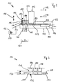
- the canape cutting machine 1 shown in FIG. 1 has a frame 2, which is essentially a cutting unit 3, a bread slice magazine 4 and a bread slice feed carriage 5.
- the cutting unit 3 has in this embodiment, a total of three cutting blades 6, 7 and 8.
- the right front cutting blade 6, the left front cutting blade 7 and the middle rear cutting blade 8 are mounted in the cutter 3 such that the cutting blades 6, 7 and 8 upon actuation of a Cutting mechanism lever 9 perform a lifting movement according to the double arrow 10.
- a cutter cover 11 (here only schematically indicated).
- the bread slice magazine 4 is arranged, which from the top in the direction of arrow 12, for example, with slices of toast is fitted, so that in each case the lower toast slice 13 a bread supporting surface 14 by means of the bread slice driving carriage 5
- Cutting unit 3 can be supplied.
- Exemplary is in the area of Cutting unit 3 a previously delivered Toastbrotusion 15 schematically shown.
- the delivery of Toastbrotusion 15 is done by means of Bread slice feed carriage 5, which by a drive motor 16 via a Zustellstellschlittengetriebe 17 according to a feed movement 18 and a Return movement 19 is moved.
- the toast bread slices provided in the bread slice magazine 4 become in this embodiment, due to gravity against the Bread support surface 14 is pressed, so always a lower Toastbrotular 13 arranged in the region of the bread slice magazine 4 on the bread support surface 14 is, as long as the bread slice magazine 4 sufficient with Toastbrotusionn is equipped.
- the cutter 3 and the bread slice feed carriage are 5 coordinated such that a feed 18 of the Brotusionnzustfahrschlittens 5 is excluded while the cutting blade 6, 7 and 8 of the cutting unit 3 an added Toastbrotusion 15th to cut.
- the canape cutter since the bread slice feed carriage 5 is moved, the canape cutter has 1 in the area of this bread slice feed carriage 5 a Brotusionnzustellschlittenabdeckung 25, so that the immediate Access in the area of the moving bread slices auxiliary carriage 5 in particular is prevented during operation of the canape cutting machine 1.
- the canape cutting machine 101 shown in FIG. 2 has substantially the same structure as the canape cutting machine 1 of the figure 1.
- the canape cutting machine 101 also includes a frame 102, in FIG which mainly a cutting mechanism 103, a sliced bread 104 and a bread slice feeding carriage 105 are disposed.
- the cutter 103 has a right front cutter 106, a left front cutter 107 and a rear middle cutter 108, which together a lifting movement according to the double arrow 110th can execute.
- the bread slice magazine 104 arranged in which a plurality of slices of toast in the direction of the arrow 112 is fillable. As long as 104 slices of toast in the sliced bread magazine are located below the bread slice magazine 104 always a lower toast loaf 113th This lower Toastbrotusion 113 lies on a bread support surface 114 of the canape cutting machine 101 and is by means of the slice opening carriage 105th supplied to the cutting unit 103 as needed.
- the Brotusionnzustellschlitten 105 on the one hand a feed 118 with a thereto perform subsequent return movement 119.
- To access the Bread slice feed carriage 105 in particular during operation of the Canape cutting machine 101 is the entire area around the bread slice feed carriage 105 by means of a feed slide cover 125 protected.
- the feed carriage 105 is via a feed slide 117 by means a drive motor 116 moves.
- the linkage 126 shown here is designed such that during a return stroke of the cutting knives 106, 107 and 108 of the Brotusionnzustfahrschlitten 105 executes a feed 118 and thereby a lower toast loaf 113 leads into the region of the cutting unit 103.
- toast slices 122 are out of the range pushed the cutting unit 103.
- These slices of bread slices 122 become passed over a Resterisone 123 to a Resteauffang essenceer 124.
- the finished cut or stamped canape shelves 120 fall In contrast, in a Canape-collecting container 121, in which they for a Further processing ready.
- the cutting unit 103 shown by way of example in FIG. 3, of the canape cutting machine 101 of FIG. 2 has a cutting blade stroke 130 on which the cutting blades 106, 107 and 108, starting from a rest position 131 to perform a cutting position 132. Marked here the rest position 131 the position of the respective lower edge of the individual Cutting knives 106, 107 and 108 before the cutting operation and the cutting position 132, the lower edge of the cutting blades 106, 107 and 108 shortly after the actual cutting process and before the backward movement of the Divisor 106, 107 and 108 in the rest position 131.
- the delivered Toast slice 115 (see Figure 2) rests on the bread support surface 114 of a so-called Ausstechmatrize 133 on.
- the canape cutting machine 201 shown in FIG. 4 faces the above-described canape cutting machines 1 and 101 in the area the cutting unit 203 below the frame 202 adjustable feet 227 (shown here only as an example) on what the canape cutting machine is about 201 is supported against a ground 248.
- adjustable feet 227 shown here only as an example
- the cutter 203 has to apply the manual force 236 via a cutting mechanism lever 209 which at one end to a bearing block 229th is rotatably mounted.
- the bearing block 229 is fixedly connected to the frame 202.
- About a print run 235 is one on the cutting unit lever 209 manually applied force 236 transferred to the cutting unit 203, so Cut out the canape bottoms from the sliced toast become.
- the bread slice feed slide 205 has in addition in this embodiment a hand knob 240, on which the feed carriage 205 packed and according to the already explained manner in a delivery movement 218 and a return movement 219 in the frame 202 of the canape cutting machine 201 can be moved back and forth.
- a delivery a lower toast slice 13 alternatively possible even if For example, no electricity for operating the drive motor available stands.
- the cutting unit 203 is arranged, immediately behind the cutting unit 203 is the bread slice magazine 204.
- the bread slice magazine 204 is characterized on the one hand by a Brotusionnmagazinein Stahl 241 and on the other by a lateral magazine engagement 242 out.
- a Brotusionnmagazinein Stahl 241 is the filling height of the bread slice magazine 204 visually particularly easy to capture. Also let bread slices 255, which may have jammed, especially simply correct in position within the slice of bread slice 204.
- the cutter 203 includes a right front cutter 206, a left front cutter 207 and a rear middle cutter 208. All cutting blades 206, 207 and 208 are in a cutting blade retaining plate 243 arranged.
- the cutting blade retaining plate 243 is in turn four guide pins 244 (numbered here only as an example) out.
- a Ausstechmatrize 233 (see Figure 8) proceed, which forms the bread support surface 214.
- Brotauflage Chemistry 214 is the added toasted bread slice in the area of the cutting unit 203 stored.
- a retaining plate 245 (see also Figure 8) is arranged, in which the Cutting knives 206, 207 and 208 are guided.
- the retaining plate 245 become slices of bread slices 122 during the return stroke of the Cutting knives 206, 207 and 208 are retained so that these slices of toast slices between the retaining plate 245 and the Ausstechmatrize 233 remains until the feed carriage 205 another lower Toast bread slice undelets and the slices of toast through the bottom Toast bread slice from the cutting unit 203 is also transported.
- the Toasted bread slices are left over a Resterisone 223 from the canape slicer 201 led away.
- the finished canape floors will be accordingly by means of a canape-floors-slide from the area of the Cutting unit 203 led away.
- the rack 202 of the canape cutter 201 has a right side bolster 246 and a left side cheek 247 on.
- the right side cheek 246 and the left side cheek 247 are not in the area of the cutting unit 203 completely formed to a pad 248, thus the discharge remove the finished canape bottoms from the area of the cutting unit 203.
- the cutting unit 203 is preferably over a bottom edge arranged out so that the finished canape floors 220 not on the Pad 248 fall, but past this pad 248 in a corresponding Canape collection container 221 (see Figure 2) or on a Canape-floors chute 228.
- a handle 229 is arranged, with which the canape cutting machine 201 can be kept advantageous during transport.
- the canape cutting machine 201 on its underside in this embodiment, several suction feet 237 on.
- the canape cutting machine 201 has on the base 248 a particularly good grip.
- To facilitate cleaning work has the canape slicer 201 below the sliced bread magazine 204 on the pad 248 side facing a cleaning flap 238th through which the inside of the canape cutting machine 201 is easily accessible is.
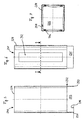
- the bread slice magazine 204 (see Figs. 5-7) has one substantially rectangular cross-section and is made in this embodiment a stainless steel profile with a wall thickness of 1.5 mm.
- the Bread slice magazine 204 has at its the bread slice magazine filling opening 241 opposite end a right side bar 250 and a Left side bar 251, so that when setting up the bread slice magazine 204 on a bread support surface 214 between this Brotauflagen constitutional 214 and a Viscoberkante 252 a gap 253 established.
- a lower slice of toast can be arranged such that this lower toast bread slice by means of the bread slice feed slide 205 can be guided to the cutting unit 203.
- the guide inserts 256 are made in this embodiment made of a plastic and are glued to the inside 254.
- the cutter 203 of the canape cutter 201 has a snow knife holding plate 243, in which the three cutting blades 206, 207 and 208 are arranged and held.
- the cutting blade retaining plate 243 is in four guide pins 244 (here only exemplified numbered) out and is by means of return springs 257 in an upper position 258 of the guide pins 244th held. In this embodiment, each of the four guide pins 244 such a return spring 257 on.
- the cutter 203 has a Ausstechmatrize 233, a Brotauflage Structure 214, for example, for an added Toastbrotin 215, provides. So after the cutting process Toast bread slices the served toast bread slice 215 not with the cutting blades 206, 207 and 208 in the direction of the upper position 258 taken be, has the cutting unit 203 between the Schneidmesserhalteplatte 243 and the Ausstechmatrize 233 a retaining plate 245, which the slices of bread slices of the slices of toasted bread 215 are interposed the retaining plate 245 and the Ausstechmatrize 233 holds, so that the Toast slices by a feed movement 218 (see Figure 4) a be transported to another toast bread slice.
- a feed movement 218 see Figure 4
- the cutting blade holding plate 243 shown in FIG Corner areas each have a guide bore 259, which the guide pins Record 244.
- the cutting blade retaining plate has 243 a first cutting blade receiving bore 260, a second Cutting blade receiving bore 261 and a third cutting blade receiving bore 261 on.
- the cutting unit 203 additionally has a Clamping guide 263 (see Figure 10), which in turn to a Retaining plate groove 264 and on the other a Ausstechmatrizennut 265th has (see Figures 10 and 11).
- the clamping guide 263 has it Beyond retaining holes 266 (here only exemplified) on which the Receiving the guide pins 244 serve. In the retaining holes 266 are the return springs 257 already described in more detail in the figure 8 stored.
- the clamping guide 263 also has a passage opening 267, through which the cut canape bottoms after cutting out or cutting out of the area of the cutting unit 203 fall (see FIG. 11).
- the guide pins 244 are in their lower regions 268 (see FIG. 12). chamfered so that they are much easier inserted into the retaining holes 266 can be. In the upper guide pin area 269, the guide pin 244 a guide pin thread 270, with which he form-fitting can be connected to the Schneidmesserhalteplatte 243.
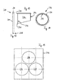
- the cutting blade 206 shown in Figures 13 and 14 has in his lower area a sharpness 271 on.
- the Sharpness 271 incorporated on the cutting knife inside 272.
- the sharpness 271 is at the outer shell surface 273 of the cutting blade 206 worked.
- Such arranged on the outer circumferential surface 273 of the cutting blade 206 Sharpness 271 is advantageous because in this case the inner cylinder of Cutting blade 206 is not tapered by an internally chamfered sharpness 271.
- the danger is reduced that the cutting bread indoors the cutting blade 206 compressed during cutting, that the sliced bread in the inner cylinder of the cutting knife 206 jammed and no longer advantageous solely on the basis of gravity from the inner cylinder of the cutting blade 206 passes.
- the cutting knife 206 On the opposite side of the sharpness 271, the cutting knife 206 in both cases, a circumferential ridge 274 on.
- the web 274 serves as Stop and positioning means, so that the cutting blade 206 vertically in the cutting blade holding plate 243 can be arranged.
- the plate 275 shown in Figure 15 has a first cutter blade passage bore 276, a second cutting blade passage bore 277 and a third cutting knife passage bore 278.
- the plate 275 can both as a retaining plate 245 and as Ausstechmatrize 233 of the Cutting unit 203 can be used.
- the bread slice feed carriage 205 shown in Figs. 16 and 17 has in its upper part the additional hand knob 240, by means of which of the bread sliver feed carriages 205 cumulatively or alternatively in FIG a feed 218 and a return movement 219 manually out and can be moved.
- a Zustellschlittengetriebe arranged 217, about which the Brotusionnzustellschlitten 205 is operatively connected to a drive motor.
Landscapes
- Life Sciences & Earth Sciences (AREA)
- Engineering & Computer Science (AREA)
- Food Science & Technology (AREA)
- Manufacturing And Processing Devices For Dough (AREA)
Applications Claiming Priority (4)
| Application Number | Priority Date | Filing Date | Title |
|---|---|---|---|
| DE10347865 | 2003-10-11 | ||
| DE10347865 | 2003-10-11 | ||
| DE102004006631A DE102004006631A1 (de) | 2003-10-11 | 2004-02-10 | Vorrichtung und Verfahren zum Herstellen von Canape |
| DE102004006631 | 2004-02-10 |
Publications (1)
| Publication Number | Publication Date |
|---|---|
| EP1523888A2 true EP1523888A2 (fr) | 2005-04-20 |
Family
ID=34379085
Family Applications (1)
| Application Number | Title | Priority Date | Filing Date |
|---|---|---|---|
| EP20040022306 Withdrawn EP1523888A2 (fr) | 2003-10-11 | 2004-09-20 | Dispositif et procédé de fabrication de canapé |
Country Status (1)
| Country | Link |
|---|---|
| EP (1) | EP1523888A2 (fr) |
-
2004
- 2004-09-20 EP EP20040022306 patent/EP1523888A2/fr not_active Withdrawn
Similar Documents
| Publication | Publication Date | Title |
|---|---|---|
| EP2353407B1 (fr) | Dispositif d'entaillage ou de coupe de fruits ayant une coque dure, notamment des châtaignes ou des marrons, et procédé associé | |
| DE3872134T2 (de) | Verfahren und vorrichtung zum ausbeinen von fleischstuecken, insbesondere von abgetrennten tierkoepfen. | |
| DE4431808C2 (de) | Verfahren zum schrittweisen Schneiden bzw. Zertrennen von Nahrungsmitteln und Schneidmaschine zum Durchführen dieses Verfahrens | |
| EP2807003B1 (fr) | Trancheuse de pain avec dispositif d'avance | |
| DE652383C (de) | Maschine zum Fischfiletschneiden | |
| DE202011005113U1 (de) | Brotschneidemaschine | |
| DE69714154T2 (de) | Gerät, messer und verfahren zum schneiden entlang spinalenfortsätzen in einer karkasse oder karkassenteil | |
| EP2241421B1 (fr) | Dispositif pour portionner des aliments | |
| WO2013110689A1 (fr) | Dispositif destiné à trancher et à emballer du pain | |
| EP3732974A1 (fr) | Dispositif de découpage ainsi que procédé de découpage d'un produit | |
| DE1657656C3 (de) | Vorrichtung zum Zerspanen gefrorener Fleischblöcke | |
| EP0306012A2 (fr) | Méthode et appareil pour couper des produits alimentaires | |
| WO2013110688A1 (fr) | Dispositif de tranchage de pain | |
| DE60127006T2 (de) | Holzschneid und -Spaltvorrichtung | |
| EP1523888A2 (fr) | Dispositif et procédé de fabrication de canapé | |
| EP3782783B1 (fr) | Machine de coupe | |
| DE10222754C1 (de) | Maschine zum Heraustrennen von Rippen aus Schweinebäuchen | |
| DE102010016159A9 (de) | Brotschneidemaschine | |
| DE102004006631A1 (de) | Vorrichtung und Verfahren zum Herstellen von Canape | |
| EP2807005B1 (fr) | Trancheuse de pain avec dispositif de nettoyage | |
| DE202016102386U1 (de) | Vorrichtung zum Schneiden von Lebensmitteln | |
| DE19614125A1 (de) | Blechkuchenschneidemaschine | |
| DE920441C (de) | Maschine zum Abtrennen von Fischkoepfen | |
| DE202010000474U1 (de) | Brotschneidemaschine | |
| DE69118519T2 (de) | Konditionieren von in Scheiben geschnittenen Tabakballen |
Legal Events
| Date | Code | Title | Description |
|---|---|---|---|
| PUAI | Public reference made under article 153(3) epc to a published international application that has entered the european phase |
Free format text: ORIGINAL CODE: 0009012 |
|
| AK | Designated contracting states |
Kind code of ref document: A2 Designated state(s): AT BE BG CH CY CZ DE DK EE ES FI FR GB GR HU IE IT LI LU MC NL PL PT RO SE SI SK TR |
|
| AX | Request for extension of the european patent |
Extension state: AL HR LT LV MK |
|
| STAA | Information on the status of an ep patent application or granted ep patent |
Free format text: STATUS: THE APPLICATION IS DEEMED TO BE WITHDRAWN |
|
| 18D | Application deemed to be withdrawn |
Effective date: 20070331 |