EP1523409B1 - Procede pour reduire les vibrations au niveaux d'elements rotatifs et element rotatif correspondant amorti en vibrations - Google Patents
Procede pour reduire les vibrations au niveaux d'elements rotatifs et element rotatif correspondant amorti en vibrations Download PDFInfo
- Publication number
- EP1523409B1 EP1523409B1 EP03787653A EP03787653A EP1523409B1 EP 1523409 B1 EP1523409 B1 EP 1523409B1 EP 03787653 A EP03787653 A EP 03787653A EP 03787653 A EP03787653 A EP 03787653A EP 1523409 B1 EP1523409 B1 EP 1523409B1
- Authority
- EP
- European Patent Office
- Prior art keywords
- elevation
- soll
- height
- component
- actuator
- Prior art date
- Legal status (The legal status is an assumption and is not a legal conclusion. Google has not performed a legal analysis and makes no representation as to the accuracy of the status listed.)
- Expired - Lifetime
Links
- 238000000034 method Methods 0.000 title claims abstract description 19
- 238000005096 rolling process Methods 0.000 claims description 13
- 230000008859 change Effects 0.000 claims description 6
- 230000001105 regulatory effect Effects 0.000 claims description 3
- 238000012546 transfer Methods 0.000 description 14
- 230000010354 integration Effects 0.000 description 7
- 238000005457 optimization Methods 0.000 description 5
- 230000010355 oscillation Effects 0.000 description 5
- 230000009467 reduction Effects 0.000 description 5
- 238000004519 manufacturing process Methods 0.000 description 4
- 230000001276 controlling effect Effects 0.000 description 3
- 230000000694 effects Effects 0.000 description 3
- 230000005284 excitation Effects 0.000 description 3
- 239000002184 metal Substances 0.000 description 3
- 230000001133 acceleration Effects 0.000 description 2
- 230000015572 biosynthetic process Effects 0.000 description 2
- 230000001419 dependent effect Effects 0.000 description 2
- 239000000463 material Substances 0.000 description 2
- 230000007246 mechanism Effects 0.000 description 2
- 238000012545 processing Methods 0.000 description 2
- 230000004913 activation Effects 0.000 description 1
- 230000003044 adaptive effect Effects 0.000 description 1
- 230000008901 benefit Effects 0.000 description 1
- 230000008033 biological extinction Effects 0.000 description 1
- 238000005520 cutting process Methods 0.000 description 1
- 238000013016 damping Methods 0.000 description 1
- 238000011161 development Methods 0.000 description 1
- 238000010586 diagram Methods 0.000 description 1
- 238000006073 displacement reaction Methods 0.000 description 1
- 239000012530 fluid Substances 0.000 description 1
- 230000005484 gravity Effects 0.000 description 1
- 238000005259 measurement Methods 0.000 description 1
- 230000008092 positive effect Effects 0.000 description 1
- 230000004044 response Effects 0.000 description 1
- 230000002441 reversible effect Effects 0.000 description 1
- 230000008093 supporting effect Effects 0.000 description 1
- 230000001360 synchronised effect Effects 0.000 description 1
- 238000012549 training Methods 0.000 description 1
Images


Classifications
-
- F—MECHANICAL ENGINEERING; LIGHTING; HEATING; WEAPONS; BLASTING
- F16—ENGINEERING ELEMENTS AND UNITS; GENERAL MEASURES FOR PRODUCING AND MAINTAINING EFFECTIVE FUNCTIONING OF MACHINES OR INSTALLATIONS; THERMAL INSULATION IN GENERAL
- F16F—SPRINGS; SHOCK-ABSORBERS; MEANS FOR DAMPING VIBRATION
- F16F15/00—Suppression of vibrations in systems; Means or arrangements for avoiding or reducing out-of-balance forces, e.g. due to motion
-
- B—PERFORMING OPERATIONS; TRANSPORTING
- B41—PRINTING; LINING MACHINES; TYPEWRITERS; STAMPS
- B41F—PRINTING MACHINES OR PRESSES
- B41F13/00—Common details of rotary presses or machines
- B41F13/08—Cylinders
- B41F13/085—Cylinders with means for preventing or damping vibrations or shocks
-
- Y—GENERAL TAGGING OF NEW TECHNOLOGICAL DEVELOPMENTS; GENERAL TAGGING OF CROSS-SECTIONAL TECHNOLOGIES SPANNING OVER SEVERAL SECTIONS OF THE IPC; TECHNICAL SUBJECTS COVERED BY FORMER USPC CROSS-REFERENCE ART COLLECTIONS [XRACs] AND DIGESTS
- Y10—TECHNICAL SUBJECTS COVERED BY FORMER USPC
- Y10T—TECHNICAL SUBJECTS COVERED BY FORMER US CLASSIFICATION
- Y10T74/00—Machine element or mechanism
- Y10T74/20—Control lever and linkage systems
- Y10T74/20576—Elements
- Y10T74/20732—Handles
- Y10T74/20762—Shaft connections
- Y10T74/20768—Engine starter type
Definitions
- the invention relates to a method for reducing vibrations on rotating components and a vibration-damped rotating component according to the preamble of claim 1 and 8, respectively.
- the EP 01 94 618 B1 discloses a device for reducing vibrations caused by the rolling over of a channel located on the lateral surface.
- an elevation of the circular contour for influencing the force change behavior is arranged in the inlet and / or outlet region of the channel.
- WO 01 50 035 A1 discloses a method for compensating vibrations of rotating components, wherein an actuator in the region of a lateral surface of the rotating component is arranged, and counteracts an activation in dependence on the rotational angle position of the rotating component of the vibration with a force component in the axial direction.
- the invention has for its object to provide a method for reducing vibrations on rotating components and a vibration-damped rotating component.
- the achievable with the present invention consist in particular that a possibility has been created to reduce vibrations effectively and variably.
- the Reduction of the oscillation can take place actively during the running production and if necessary adaptively and adapted to operating conditions.
- the method is advantageous on at least one of two successive rolling rotating components, for.
- cylinders or rollers can be used, wherein at least one of the components seen in the circumferential direction on its lateral surface at least one interruption, z. B. a channel having.
- a fernbetätigbarer actuator is acted upon with pressure medium actuator, for. B. as a hydraulic or pneumatic unit executed. In one variant, it is formed piezzoelektrisch.
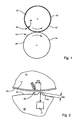
- the two in the following as cylinder 01; 02 designated components 01; 02 roll during operation in the area of their effective lateral surfaces 03; 04 on each other and are in Anstelllage AN with a z. B. specifiable or adjustable force to each other ( Fig. 1 ).
- the invention is also advantageously applicable to rollers and cylinders in working machines for the production of band-shaped material, for. As paper or sheet, etc., in impression rollers or rolling mills.
- At least one of the cylinders 01; 02, here z. B. running as a transfer cylinder 01 cylinder 01, has at least one axially extending interruption 06 in the region of its effective lateral surface 03 of a non-stressed state otherwise circular contour.
- the interruption 06 is based, for example, on a joint of ends of one or more elevators 07 arranged on the cylinder 01 or on the fact that ends of one or more elevators 07 are arranged in a channel 08 extending axially in the region of the cylinder surface 01 near the jacket surface.
- An opening from the lateral surface of the cylinder 01 to the channel 08 is kept as small as possible in the circumferential direction and is in an advantageous embodiment a maximum of 3 mm.
- the channel 08 can expand towards the interior and a device for clamping and / or clamping 10 (FIG. Fig. 4 ) exhibit. However, it can also be designed as a slot 08.
- the two cylinders 01; 02 are employed in anstelllage AN with a force greater than zero to each other and experienced at passage of the interruption 06 by the Nippstelle a discharge and a subsequent re-load.
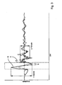
- a vibration of the cylinder 01; 02 or the cylinder 01; 02 stimulated, among other things, by the adjusting forces, the geometries of break 06 and cylinder 01; 02, the Material properties and the speed or an unwinding speed v is dependent
- Curve A such a vibration is qualitatively represented, wherein the dashed area designates the passage of the interruption 06 in the Nippstelle.
- At least one of the cylinders 01; 02, here z At least one of the cylinders 01; 02, here z.
- the cylinder 02 designed as a forme cylinder 02 in the region of its effective lateral surface 04, at least one axially extending elevation 09 from an otherwise circular contour in the unloaded state.
- This elevation 09 can extend axially over a length of the effective bale or else in one or more sections in the axial direction.
- the elevation 09 has a height h09 (of the maximum) with respect to the undisturbed contour and an effective distance a09 (the maximum) of the interruption 06 with respect to a Abrollweg to the unwound cylinders 01; 02 on.
- this countervibration causes an increase or decrease (ideally extinction) of the caused by the passage of the interrupt 09 oscillation amplitude.
- the elevation 09 unfolds, depending on the shape and position, a supporting action between the cylinders 01 which move radially relative to one another by excitation; 02.
- Fig. 3 is a resulting by superposition of the vibration and counter-vibration course for the resulting curve B of the vibration is shown, wherein the excitation by the elevation 09 in the form of a ramp (see below) was generated.
- the elevation 09 is now designed such that its height h09 compared to the undisturbed contour, especially during operation, ie during the rolling of the cylinder 01; 02, is changeable.
- the cylinder 02 means 11 for changing the height h09, z.
- the distance a09 ( Fig. 4 ) made changeable.
- the elevation 09 is technically feasible in different ways.
- radially movable provided with a suitable shape fingers comb-like in recesses on the lateral surface of the main body of the cylinder 01; Be sunk 02 and be radially movable via an adjusting means 11 by linear or rotary movement.
- an area of the lateral surface 03; 04 elastically deformable or elastically resilient executed within certain limits, and by an arranged inside the cylinder actuating means 11, z.
- cam or eccentric shaft or other actuators is deflectable in the radial direction
- the actuator 11 and actuators 11 can in different ways, for. B. depending on the configuration of the elevation 09, be executed. It may be implemented as part of a motor, hydraulically or pneumatically driven unit, based on magnetic or piezoelectric forces unit.
- the device and the method using the example of a tongue / lip / tab 09 executed elevation 09 is shown, which is substantially reversible baumfedemd from the contour of the lateral surface 03; 04 is bendable out.
- the tongue / lip / tab 09 actuating actuator 11 is designed here as part of a hydraulically active unit.
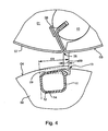
- Fig. 4 has the cylinder 02 acting together with the transfer cylinder 01, in this case the forme cylinder 02, the deployable tongue / lip / tab 09.
- the tongue / lip / tab 09 is in the form of a one-armed lever by a within the lateral surface 04 axially extending channel 12 and the channel 12 with the environment connecting interruption 13 of the lateral surface, for. B.
- the tongue / lip / tab 09 can be erected by the hydraulic unit, which has as an actuator 11 beauchtbaren with pressure medium, reversibly deformable hollow body 11 in the axially extending in the cylinder 02 channel 12.
- the hollow body 11 is arranged directly below the tongue / lip / tab 09 in the interior of the cylinder 02 and is supported in the radial direction inwards at least in regions on a cylinder-fixed surface 14.
- Fig. 4 is also the effective distance a09 between the maximum elevation 09 (here the cut edge) and the interruption 06, and an effective leg length 109 of the tongue / lip / tab 09 shown
- the effective leg length 109 sets the length of the tongue / lip / tab 09 in the circumferential direction from the cutting edge to the point at which the tongue / lip / tab 09 is "undermined" through the channel 12 as seen in the radial direction.
- the tongue / lip / tab 09 extends in an advantageous embodiment over the entire length of a bale of the cylinder 02.
- the tongue / lip / tab 09 is shown in an active position, ie the actuator 11 is effective.
- a plurality of juxtaposed in the axial direction interruptions 06 are arranged circumferentially offset from one another, and several elevations 09 can be arranged in the same way staggered.
- the executed as a hollow body 11 actuator 11 refers to its fluid or the pressure P z. B. via a rotary feedthrough not shown in the region of a pin, not shown, of the cylinder 03 from outside.
- the forme cylinder 02 cooperates in Anstelllage with the transfer cylinder 01, on the lateral surface of the elevator 07, z. B. a blanket 07, is curious.
- Ends 16; 17 of the same or two different in the circumferential direction successively arranged elevators 07 are held by a located in the channel 08 clamping and / or clamping device.
- the interruption 06 forms in the effective lateral surface 03 from.
- the distance a09 is in an advantageous embodiment of a length which a path on the lateral surface 03; 04 of a sector of the cylinder 01; 02 with an opening angle of -1 to 8 °, in particular 3 to 6 ° corresponds.
- the tongue / lip / tab 09 has an effective leg length 109 of 10 to 30 mm, in particular from 16 to 21 mm.
- the distance a09 is z. B. 1.25 to 15 mm, in particular 4 mm to 10 mm.
- the ratio between distance a09 and the circumference is between 0.002 and 0.02, in particular between 0.005 and 0.015.
- the ratio between leg length I09 and the circumference is between 0.02 and 0.04, in particular between 0.03 and 0.035.
- elevation 09 as tongue / lip / tab 09 is with respect to the direction of rotation of the cylinder 01; 02 or the cylinder 01; 02 executed asymmetrically.
- the elevation 09 acts in a ramped fashion with a correspondingly shaped impulse, while in another direction of rotation a collision is induced at a discontinuous discontinuity.
- Both forms show the effect described above, but the excitation with passing through the ramp / the direction of rotation with unsteady discontinuity is of greater advantage
- the height h09 and / or the distance a09, depending on the direction of rotation, speed and strength of the delivery (line force) of the cylinder 01; 02 can be set differently.
- the direction of rotation can be supplied to a control or regulation explained below as a variable g characterizing the machine state or the machine.
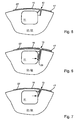
- FIGS. 5 to 7 are different variants for the integration of a clamping device for the elevator 07 and its ends 16; These arrangements are applicable both to elevators 07 designed as printing plates 07 on the forme cylinder 02 or as blankets 07 on the transfer cylinder 01.
- the use of metal printing plates 07 is advantageous, since these are in the region of their ends 16; 17 similar to those of printing plates 07 can be designed and clamped in the channel 08.
- the interruption 13 is designed as an opening 13 in such a way that it is very narrow, less than or equal to 3 mm, with the ends 16; 17, z. B. elevator ends 16; 17 are only hung.
- the interruption 13 is designed as an opening 13 in such a way that the actuator 11 simultaneously, either via a lever mechanism 20 (only schematically indicated) or directly to one or two elevator ends 16; 17 acts and this jams.
- the interruption 13 is designed as an opening 13 in such a way that, for example, the leading elevator end 16 is held substantially by the shape of the edge, and the trailing elevator end 17 is clamped by the actuator 11.
- the elevation 09 is variable in its height h09.
- exemplary embodiments of the method for the control and the device required for this purpose are presented.
- a timing chain which may include a subordinate control loop.
- a reference variable of the parent control chain is a machine state, in particular the unwinding speed v characterizing size v, such. B. the speed or the angular velocity
- This size v can, for. B. with other the machine state or the machine characterizing quantities g, taken from a higher-level machine control or else be measured in a suitable manner.
- the value v is now assigned in a logical unit 18 based on a stored relationship (tabular, arithmetic, etc.), a target value for the manipulated variable as the output of the logical unit 18.
- the manipulated variable can directly a desired height h09 of the elevation 09, a pressure P, a path S, a Be voltage U etc. Accordingly, z. B.
- h09 SOLL for the height h09 of the elevation 09
- P SOLL for the pressure P of a hydraulic unit
- S SOLL for a displacement or position signal S of an actuator 11
- U SOLL for the voltage signal U an actuator 11 set.
- This setpoint h09 SHOULD ; P SOLL ; S SOLL ; U SOLL serves as a subordinate control 19 again as a reference variable.
- Logic in the logic unit 18 is a functional or algebraic, in particular linear, relationship between the unwinding speed v and the desired overshoot 09 (or a corresponding path, pressure, voltage signal) ( Fig. 9 ).
- This (in particular linearized) relationship between the unwinding speed v and the desired value h09 SOLL ; P SOLL ; S SOLL ; U SOLL for the height h09 of the elevation 09 or the pressure P, the path S or the voltage U can be present multiple times for different cylinder geometries and / or for the machine state or the machine characterizing quantities g and be selected accordingly ( Fig. 9 : Connections C, D).
- connection can advantageously also be used for starting and starting up the printing press, so that a suitable elevation 09 is present for each unwinding speed v
- the regulation allows in training by their adaptive structure an optimization of the real production conditions or environments.
- a linearized relationship between rolling speed v and the desired value SOLL for the pressure P P deposited This logic may also be a known relationship between the pressure P in the hollow body 11 and the resulting height h09 of the elevation 09 are based.
- the actuator 11 which is in the form of a hollow body 11, is acted upon and, if necessary, maintained by means of the controlled system 22 embodied as a valve 22, with an actual value P IST being fed back into the subordinate control loop (the same applies to Pressure P different manipulated variables S; U; h09).
- the tongue / lip / flap 09 is thus raised in response to the unwinding speed v corresponding to the applied pressure P IST by the corresponding height h09 and held there. If the unwinding speed v or another production condition changes, the pressure P (or other control variables) is redetermined and set. A check of the unwinding speed v need not be continuous, but may be done at discrete intervals, e.g. B. each after a certain number of cylinder revolutions done. In a further development, a lower value P SET can also be supplied to the lower-level control loop, which can be predetermined manually, for example in a start-up phase or extremely unsteady conditions, from a machine control
- the reduction is based on a higher-level control, which may again include the above-described control circuit of the subordinate control 19.
- a value e (t) characterizing the oscillation is fed into the logic unit 18 as an input variable.
- the value e (t) includes in particular a relative value between at the two cylinders 01; 02 measured amplitudes a1; a2, which on a plane through axes of rotation of the two cylinders 01; 02 are projected.
- the value e (t) is therefore also referred to as the relative amplitude e (t) oscillate the two cylinders 01; 02 in phase in this plane with the same amplitude e (t), this would give a value of zero.
- the unwinding speed v and / or others the machine state or the Machine characterizing quantities g are supplied as input.
- the logic unit 18 has an optimization algorithm which uses the values e (t) to determine the output h09 SOLL ; P SOLL that e (t) is minimized varied in such a manner.
- the variation takes place in an advantageous embodiment along in the logic unit 18 vorhaltener relationships, z. B. the dependence of the relative amplitude e (t) of the height h09 or the pressure P ( Fig. 11 ) or the distance a09.
- a set of curves or an arithmetical relationship can be specified.
- At known rolling speed v (or speed) is now a variation along the for this rolling speed v (or speed) predetermined relationship.
- a measurement of the vibration and a possibly resulting variation does not have to be continuous but is to be determined regularly after finite time intervals or over a certain number of cylinder revolutions.
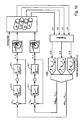
- Fig. 12 shows a Mehrwalzen- particular Verwalzensystem, the already described transfer cylinder 01 not only with its forme cylinder 02, but in Anstelllage AN with a further components 23, z. B. cylinder 23 as an impression cylinder 23, here a second transfer cylinder 23 cooperates.
- the second transfer cylinder 23 is a component 24, for. B. cylinder 24, z. B. a second forme cylinder 24, assigned, which acts in Anstelllage AN with this together.
- Of the four cylinders 01; 02; 23; 24 have z. B. only two, in particular the two transfer cylinders 01; 23 an actuator 11 and a height h09 and / or Phase position (distance a09) variable overshoot 09 on.
- the basic effect is also on other multi-control systems such.
- B. satellite pressure units with 3, 9 or 10 co-acting cylinders apply.
- Fig. 10 In analogy to the embodiment according to Fig. 10 become four amplitudes or waveforms a1; a2; a3; a4 (corresponds to number of cylinders) on the cylinders 01 involved; 02; 23; 24 determines and thereby a number of relative amplitudes e1 (t) corresponding to the number of naps; e2 (t); e3 (t) formed, which are supplied as inputs to the logic unit 18.
- the optimization algorithm now has a relationship per nip point for the respective passage of the elevation 09 or the interruption 06 through the nip point. If one of the inner cylinders 01; 23, z.
- a height h09 SOLL, 1 or a pressure P SOLL, 1 is determined in the logic unit 18 in such a way that, taking into account the two dependencies taking into account the relative amplitudes e1 (t) and e2 (t), a compromise is found which minimizes the total of the two relative amplitudes e1 (t) and e2 (t).
- the respective actuator 11.1 or 11.2 is then via the associated controller 21.1; 21.2 and the z. B.
- valve controlled system 22.1; 22.2 for the present unwinding speed v with the height h09 corresponding to this compromise or with the corresponding pressure P, 1; P2 is applied, which is on P set , 1 or P setpoint, 2 is regulated or will.
- the height h09 of the elevation 09 can now per revolution of the actuator 11 having cylinder 01; 23 are changed at least twice and in this case assumes different values at the time of passage through one or the other Nippstelle.
- the height h09 is then per revolution in dependence on the angular position of the actuator 11 having cylinder 01; 23 changed.
- each elevation 09 of the cylinder 01; 02; 23; 24, but also for all elevations 09 of a cylinder 01; 23 is a common subordinate control 19 and a common setpoint P SOLL .
- all cylinders 01; 02; 23; 24 elevations 09 and / or interruptions 06 have.
- the distance a09 (or the phase position) between interruption 06 and elevation 09 is made variable.
- this can be done mechanically by changing an effective shape of the elevation 09 or else its absolute position.
- the first case can z.
- an elevation 09 having axially extending spindle having a corresponding shape on its outer surface such that upon rotation of the spindle by an actuator, not shown, another area of the outer surface as elevation 09 is effective.
- the second case for example, in recesses on the lateral surface of the main body of the cylinder 01; 02 comb-like fingers are moved by an actuator, not shown in the circumferential direction.
- the two cooperating cylinders 01; 02; 23; 24 executed in their rotational position ⁇ mutually variable.
- the change in the relative angular position ⁇ causes in the event that interrupt 06 and associated elevation 09 on different cylinders 01; 02; 23; 24 are arranged, the change of the distance a09.
- This can be z. B. be realized such that the two cylinders 01; 02; 23; 24 are driven by means of different drive motors mechanically independent of each other rotationally.
- one of the i. d. R. electronically synchronized drive motors for the change of the distance a09 imprinted an offset in its desired angular position.
- the change of the relative rotational angular position can also be carried out with conventional mechanical devices, as are common, for example, for adjusting the position in the circumferential direction.
- the control or regulation of the distance a09 can in a corresponding manner, as to the embodiments according to 8 to 12 explained. As explained for the height h09, corresponding relationships between the unwinding speed v and the distance a09, or optimization algorithms for generating a variation in the distance a09 as a function of the relative amplitude e (t) and possibly of the unwinding speed v can then be stored.
Landscapes
- Engineering & Computer Science (AREA)
- General Engineering & Computer Science (AREA)
- Mechanical Engineering (AREA)
- Physics & Mathematics (AREA)
- Acoustics & Sound (AREA)
- Aviation & Aerospace Engineering (AREA)
- Rolls And Other Rotary Bodies (AREA)
Abstract
Claims (18)
- Procédé pour réduire des vibrations se produisant sur au moins deux composants (01 ; 02 ; 23 ; 24) rotatifs roulant l'un sur l'autre, avec au moins une surélévation (09) ressortant d'un contour sensiblement circulaire d'une surface d'enveloppe (03 ; 04) active, sur au moins l'un des composants (01 ; 02 ; 23 ; 24) rotatifs, caractérisé en ce qu'une hauteur (h09) de la surélévation (09), en direction radiale et/ou une position relative de la surélévation (09) en direction périphérique est modifiée en fonction d'une grandeur (v ; g ; a1 ; a2 ; a3 ; a4 ; e(t)) caractérisant un état machine et/ou la vibration.
- Procédé selon la revendication 1, caractérisé en ce que la hauteur (h09) et/ou la position relative de la surélévation (09) est/sont commandée(s) en fonction d'une vitesse de déroulement (v).
- Procédé selon la revendication 1, caractérisé en ce que la hauteur (h09) et/ou la position relative de la surélévation (09) est/sont régulée(s) en fonction d'une amplitude (a1 ; a2 ; a3 ; a4) déterminée sur au moins l'un des composants (01 ; 02 ; 23 ; 24).
- Procédé selon la revendication 1, caractérisé en ce que la modification de la position relative de la surélévation (09) en direction périphérique par rapport à un espacement (a09) effectif s'effectue par rapport à une interruption (06) sur une surface d'enveloppe (03 ; 04) active d'au moins l'un des composants (01 ; 02 ; 23 ; 24).
- Procédé selon la revendication 2 ou 3, caractérisé en ce que la commande ou la régulation s'effectue à l'aide d'une relation stockée préalablement dans une unité logique (18).
- Procédé selon la revendication 5, caractérisé en ce que la relation est formée par une dépendance entre une valeur de consigne (h09SOLL ; PSOLL ; SSOLL : USOLL) pour le point de fonctionnement d'un actionneur (11) et la vitesse de déroulement (v).
- Dispositif selon l'une ou plusieurs des revendications précédentes, caractérisé en ce qu'une valeur de consigne (h09SOLL ; PSOLL ; SSOLL : USOLL) pour le point de fonctionnement d'un actionneur (11) est modifiée à l'aide d'une relation stockée préalablement entre une amplitude relative (e(t)) des deux composants (01 ; 02 ; 23 ; 24) et une grandeur de réglage (h09 ; P ; S ; U) pour l'actionnement de l'actionneur (11).
- Composant rotatif amorti en vibrations, avec au moins une surélévation (09) ressortant d'un contour sensiblement circulaire d'une surface d'enveloppe (03 ; 04) active, caractérisé en ce qu'une hauteur (h09) de la surélévation (09), en direction radiale et/ou une position relative de la surélévation (09) en direction périphérique est réalisée de manière à pouvoir être modifiée en direction radiale et/ou une position relative de la surélévation (09) est réalisée de manière à pouvoir être modifiée en direction périphérique.
- Composant selon la revendication 8, caractérisé en ce qu'est prévue une chaîne de commande avec une unité logique (18), au moyen de laquelle la hauteur (h09) de la surélévation (09) et/ou une position relative de la surélévation (09) en direction périphérique est commandée en fonction d'une grandeur (v ; g) caractérisant un état machine.
- Composant selon la revendication 8, caractérisé en ce qu'est prévue une régulation avec une unité logique (18), au moyen de laquelle la hauteur (h09) de la surélévation (09) et/ou une position relative de la surélévation (09) en direction périphérique est régulée en fonction d'une grandeur (a1 ; a2 ; a3 ; a4 ; e(t)) caractérisant la vibration.
- Composant selon la revendication 8, caractérisé en ce que la surélévation (09) est réalisée à la manière d'une languette/lèvre/patte (09) dans la zone de la surface d'enveloppe d'un corps de base du composant (01 ; 02 ; 23 ; 24).
- Composant selon la revendication 11, caractérisé en ce que la languette/lèvre/patte (09) s'étend en direction axiale sur sensiblement la longueur totale (I01 ; I02) d'un corps du composant (01 ; 02 ; 23 ; 24).
- Composant selon la revendication 11, caractérisé en ce qu'un rapport, entre une longueur de branche (I09) de la languette/lèvre/patte (09) et une circonférence (U) du composant (01 ; 02 ; 23 ; 24) est dans la fourchette comprise entre 0,02 et 0,04.
- Composant selon la revendication 8, caractérisé en ce que les moyens (11) modifiant la hauteur (h09) sont réalisés sous forme d'actionneur (11) pouvant être télécommandé.
- Composant selon la revendication 14, caractérisé en ce que l'actionneur (11) est réalisé sous forme d'actionneur (11) entraîné par un fluide sous-pression.
- Composant selon la revendication 14, caractérisé en ce que l'actionneur (11) est réalisé sous forme de corps creux (1) déformable de manière réversible, disposé dans un canal (12) s'étendant axialement dans le composant (01 ; 02 ; 23 ; 24), sous la languette/lèvre/patte (09).
- Composant selon la revendication 8, caractérisé en ce que le composant (01 ; 02 ; 23 ; 24) présente une interruption (06) sur sa surface d'enveloppe (03 ; 06) active.
- Composant selon la revendication 17, caractérisé en ce qu'un rapport, entre un espacement (a09), défini par rapport à un déroulement, entre la surélévation (09) et l'interruption (06) et une circonférence (U) du composant (01 ; 02 ; 23 ; 24) est dans la fourchette comprise entre 0,002 et 0,02.
Applications Claiming Priority (5)
| Application Number | Priority Date | Filing Date | Title |
|---|---|---|---|
| DE10233086 | 2002-07-19 | ||
| DE10233086 | 2002-07-19 | ||
| DE10253997 | 2002-11-19 | ||
| DE10253997A DE10253997C1 (de) | 2002-07-19 | 2002-11-19 | Verfahren und Vorrichtung zur Verminderung von Schwingungen an rotierenden Bauteilen sowie schwingungsgedämpftes rotierendes Bauteil |
| PCT/DE2003/002348 WO2004016431A1 (fr) | 2002-07-19 | 2003-07-12 | Procede et dispositif pour reduire les vibrations au niveaux d'elements rotatifs et element rotatif correspondant amorti en vibrations |
Publications (2)
| Publication Number | Publication Date |
|---|---|
| EP1523409A1 EP1523409A1 (fr) | 2005-04-20 |
| EP1523409B1 true EP1523409B1 (fr) | 2011-03-30 |
Family
ID=31889079
Family Applications (1)
| Application Number | Title | Priority Date | Filing Date |
|---|---|---|---|
| EP03787653A Expired - Lifetime EP1523409B1 (fr) | 2002-07-19 | 2003-07-12 | Procede pour reduire les vibrations au niveaux d'elements rotatifs et element rotatif correspondant amorti en vibrations |
Country Status (4)
| Country | Link |
|---|---|
| US (1) | US7111555B2 (fr) |
| EP (1) | EP1523409B1 (fr) |
| AU (1) | AU2003250783A1 (fr) |
| WO (1) | WO2004016431A1 (fr) |
Families Citing this family (4)
| Publication number | Priority date | Publication date | Assignee | Title |
|---|---|---|---|---|
| DE102005022097A1 (de) * | 2005-05-12 | 2006-11-16 | Fraunhofer-Gesellschaft zur Förderung der angewandten Forschung e.V. | Vorrichtung und Verfahren zur Schwingungstilgung einer mechanischen Struktur |
| DE102007024767B4 (de) | 2007-05-26 | 2010-06-24 | Koenig & Bauer Aktiengesellschaft | Lagereinheit für einen Druckwerkszylinder |
| DE102010026204A1 (de) | 2010-07-02 | 2012-01-05 | Fakultät Ingenieurwissenschaften und Informatik Fachhochschule Onsabrück | Verfahren sowie Vorrichtung zur Kompensation von über den Umfang eines rotierenden insbesondere zylindrischen, Bauteils, insbesondere einer Walze, periodisch wiederkehrenden Störanregungen sowie Verfahren zur Bestimmung der Oberflächenstruktur eines ringförmigen Profils zur Kompensation der Störanregungen |
| JP7100986B2 (ja) * | 2018-01-26 | 2022-07-14 | 三菱重工機械システム株式会社 | ブランケット及びブランケット胴並びに印刷機 |
Family Cites Families (14)
| Publication number | Priority date | Publication date | Assignee | Title |
|---|---|---|---|---|
| DE2945280C2 (de) * | 1979-11-09 | 1981-06-11 | M.A.N.- Roland Druckmaschinen AG, 6050 Offenbach | Zylinder für Rotationsdruckmaschinen |
| DE3012060A1 (de) * | 1980-03-28 | 1981-10-08 | M.A.N.- Roland Druckmaschinen AG, 6050 Offenbach | Schwingungsunempfindlicher zylinder fuer druckmaschinen |
| US4738200A (en) * | 1985-03-14 | 1988-04-19 | M.A.N. Roland Druckmaschinen Aktiengesellschaft | Rubber blanket cylinder for a rotary offset printing machine |
| CA1322360C (fr) * | 1987-10-08 | 1993-09-21 | Daniel Desmond Kewin | Support de papier journal non retournable |
| US5553541A (en) * | 1989-10-05 | 1996-09-10 | Heidelberg Harris Inc | Gapless tubular printing blanket |
| US5429048A (en) * | 1989-10-05 | 1995-07-04 | Gaffney; John M. | Offset lithographic printing press |
| US5596931A (en) * | 1992-10-16 | 1997-01-28 | Heidelberger Druckmaschinen Ag | Device and method for damping mechanical vibrations of a printing press |
| US5601020A (en) * | 1993-01-22 | 1997-02-11 | Heidelberger Druckmaschinen Ag | Apparatus for reducing procession of a tubular printing sleeve |
| DE4341262C2 (de) * | 1993-01-22 | 1999-04-08 | Heidelberger Druckmasch Ag | Vorrichtung für die Reduzierung von Materialausbuchtungen auf einer rohrförmigen Druckhülse |
| DE19961574A1 (de) * | 1999-12-21 | 2001-07-19 | Koenig & Bauer Ag | Zylinder einer Rollenrotationsdruckmaschine |
| DE19963945C1 (de) * | 1999-12-31 | 2001-07-19 | Koenig & Bauer Ag | Verfahren und Anordnung zur Kompensation von Schwingungen rotierender Bauteile |
| JP3457932B2 (ja) * | 2000-07-31 | 2003-10-20 | 三菱重工業株式会社 | 円筒状ブランケット及びブランケット胴並びに印刷機 |
| US6526888B2 (en) * | 2000-12-01 | 2003-03-04 | Heidelberger Druckmaschinen Ag | Reduced vibration printing press and method |
| EP1609908B1 (fr) * | 2002-02-01 | 2008-12-31 | Koenig & Bauer Aktiengesellschaft | Procédé et dispositif pour réduire des vibrations de flexion à au moins un cylindre rotatif d`une machine d`usinage et machine d`usinage |
-
2003
- 2003-07-12 US US10/521,589 patent/US7111555B2/en not_active Expired - Fee Related
- 2003-07-12 AU AU2003250783A patent/AU2003250783A1/en not_active Abandoned
- 2003-07-12 WO PCT/DE2003/002348 patent/WO2004016431A1/fr not_active Application Discontinuation
- 2003-07-12 EP EP03787653A patent/EP1523409B1/fr not_active Expired - Lifetime
Also Published As
| Publication number | Publication date |
|---|---|
| EP1523409A1 (fr) | 2005-04-20 |
| AU2003250783A1 (en) | 2004-03-03 |
| US7111555B2 (en) | 2006-09-26 |
| US20050241433A1 (en) | 2005-11-03 |
| WO2004016431A1 (fr) | 2004-02-26 |
Similar Documents
| Publication | Publication Date | Title |
|---|---|---|
| EP1731460B1 (fr) | Corps cylindrique d'une machine de traitement de matériau de bande imprimée | |
| EP1584744B1 (fr) | Procédé pour réduire des vibrations sur des composants en rotation | |
| EP0976674B1 (fr) | Dispositif de réglage de la tension d'une bande | |
| EP2392529B1 (fr) | Contrôle de tension d'une bande en mouvement | |
| DE102007036133B4 (de) | Verfahren und Vorrichtung zur Optimierung der Schmitzringreibung | |
| EP1018426A1 (fr) | Procedé pour regler la pression entre deux cylindres d'une machine d'impression | |
| EP1523409B1 (fr) | Procede pour reduire les vibrations au niveaux d'elements rotatifs et element rotatif correspondant amorti en vibrations | |
| DE10253997C1 (de) | Verfahren und Vorrichtung zur Verminderung von Schwingungen an rotierenden Bauteilen sowie schwingungsgedämpftes rotierendes Bauteil | |
| EP0990520B1 (fr) | Méthode et dispositif de prévention de collision dans machines d'impression | |
| EP1347878B1 (fr) | Procede pour reguler un reperage circonferentiel dans une rotative a bobine | |
| EP0949075B1 (fr) | Machine à imprimer et procédé pour la mise en oeuvre d'une machine à imprimer | |
| WO2000034042A1 (fr) | Procede de regulation d'un registre | |
| DE2233879A1 (de) | Einrichtung zum einstellen der schwingungsamplitude an zickzack-falzapparaten | |
| DE10259495B4 (de) | Farbwerk einer Druckmaschine | |
| DE102006024595B4 (de) | Verfahren zum Betreiben einer Bogendruckmaschine | |
| DE10212534B4 (de) | Verfahren zum Antreiben einer Druckmaschine | |
| DE202005016767U1 (de) | Druckeinheit mit einem Formzylinder, Übertragungszylinder und Farbauftragswalze | |
| DE4411109C1 (de) | Verfahren zur Farbmengeneinstellung bei Heberfarbwerken von Druckmaschinen, insbesondere Bogenoffsetdruckmaschinen, sowie entsprechend ausgebildetes Heberfarbwerk | |
| DE102016201747A1 (de) | Verfahren zum registergenauen Bearbeiten einer Bahn | |
| EP0962317B1 (fr) | Commande pour un système d'encrage à preneur | |
| EP1494860B1 (fr) | Procede d'entrainement d'une unite d'impression | |
| DE102015201389A1 (de) | Verfahren zur Regelung eines ersten Antriebsmotors zumindest eines ersten Rotationskörpers einer Bearbeitungsmaschine für Substrat | |
| DE102009046538B4 (de) | Vorrichtungen und Verfahren zur Schwingungsreduktion | |
| EP1938988A2 (fr) | Procédé de réduction de microbandes d'encre lors de l'impression d'un produit dans une machine d'impression | |
| DE2835938A1 (de) | Verfahren und einrichtung zur steuerung von maschinen |
Legal Events
| Date | Code | Title | Description |
|---|---|---|---|
| PUAI | Public reference made under article 153(3) epc to a published international application that has entered the european phase |
Free format text: ORIGINAL CODE: 0009012 |
|
| 17P | Request for examination filed |
Effective date: 20040427 |
|
| AK | Designated contracting states |
Kind code of ref document: A1 Designated state(s): AT BE BG CH CY CZ DE DK EE ES FI FR GB GR HU IE IT LI LU MC NL PT RO SE SI SK TR |
|
| AX | Request for extension of the european patent |
Extension state: AL LT LV MK |
|
| DAX | Request for extension of the european patent (deleted) | ||
| 17Q | First examination report despatched |
Effective date: 20081104 |
|
| GRAP | Despatch of communication of intention to grant a patent |
Free format text: ORIGINAL CODE: EPIDOSNIGR1 |
|
| RTI1 | Title (correction) |
Free format text: METHOD FOR REDUCING VIBRATIONS ON ROTATING PARTS, AND VIBRATION-DAMPED ROTATING PART |
|
| RBV | Designated contracting states (corrected) |
Designated state(s): AT BE BG CH CY CZ DK EE ES FI FR GB GR HU IE IT LI LU MC NL PT RO SE SI SK TR |
|
| GRAS | Grant fee paid |
Free format text: ORIGINAL CODE: EPIDOSNIGR3 |
|
| GRAA | (expected) grant |
Free format text: ORIGINAL CODE: 0009210 |
|
| REG | Reference to a national code |
Ref country code: DE Ref legal event code: 8566 |
|
| RIN1 | Information on inventor provided before grant (corrected) |
Inventor name: GLOECKNER, ERHARD, HERBERT Inventor name: LINZ, CHRISTOF Inventor name: HANSELKA, HOLGER Inventor name: SIEBALD, HUBERTUS Inventor name: WALDSCHMIDT, AXEL Inventor name: KELLER, BERND, ULRICH, HERBERT Inventor name: TRIEBEL, GRIT Inventor name: GNAUERT, UWE Inventor name: FEHREN, HEINRICH Inventor name: KOHLRAUTZ, DANIEL |
|
| AK | Designated contracting states |
Kind code of ref document: B1 Designated state(s): AT BE BG CH CY CZ DK EE ES FI FR GB GR HU IE IT LI LU MC NL PT RO SE SI SK TR |
|
| REG | Reference to a national code |
Ref country code: GB Ref legal event code: FG4D Free format text: NOT ENGLISH |
|
| REG | Reference to a national code |
Ref country code: CH Ref legal event code: EP |
|
| REG | Reference to a national code |
Ref country code: IE Ref legal event code: FG4D |
|
| REG | Reference to a national code |
Ref country code: NL Ref legal event code: VDEP Effective date: 20110330 |
|
| PG25 | Lapsed in a contracting state [announced via postgrant information from national office to epo] |
Ref country code: GR Free format text: LAPSE BECAUSE OF FAILURE TO SUBMIT A TRANSLATION OF THE DESCRIPTION OR TO PAY THE FEE WITHIN THE PRESCRIBED TIME-LIMIT Effective date: 20110701 Ref country code: SE Free format text: LAPSE BECAUSE OF FAILURE TO SUBMIT A TRANSLATION OF THE DESCRIPTION OR TO PAY THE FEE WITHIN THE PRESCRIBED TIME-LIMIT Effective date: 20110330 |
|
| PG25 | Lapsed in a contracting state [announced via postgrant information from national office to epo] |
Ref country code: SI Free format text: LAPSE BECAUSE OF FAILURE TO SUBMIT A TRANSLATION OF THE DESCRIPTION OR TO PAY THE FEE WITHIN THE PRESCRIBED TIME-LIMIT Effective date: 20110330 Ref country code: FI Free format text: LAPSE BECAUSE OF FAILURE TO SUBMIT A TRANSLATION OF THE DESCRIPTION OR TO PAY THE FEE WITHIN THE PRESCRIBED TIME-LIMIT Effective date: 20110330 Ref country code: CY Free format text: LAPSE BECAUSE OF FAILURE TO SUBMIT A TRANSLATION OF THE DESCRIPTION OR TO PAY THE FEE WITHIN THE PRESCRIBED TIME-LIMIT Effective date: 20110330 |
|
| REG | Reference to a national code |
Ref country code: IE Ref legal event code: FD4D |
|
| PG25 | Lapsed in a contracting state [announced via postgrant information from national office to epo] |
Ref country code: EE Free format text: LAPSE BECAUSE OF FAILURE TO SUBMIT A TRANSLATION OF THE DESCRIPTION OR TO PAY THE FEE WITHIN THE PRESCRIBED TIME-LIMIT Effective date: 20110330 Ref country code: PT Free format text: LAPSE BECAUSE OF FAILURE TO SUBMIT A TRANSLATION OF THE DESCRIPTION OR TO PAY THE FEE WITHIN THE PRESCRIBED TIME-LIMIT Effective date: 20110801 |
|
| PG25 | Lapsed in a contracting state [announced via postgrant information from national office to epo] |
Ref country code: ES Free format text: LAPSE BECAUSE OF FAILURE TO SUBMIT A TRANSLATION OF THE DESCRIPTION OR TO PAY THE FEE WITHIN THE PRESCRIBED TIME-LIMIT Effective date: 20110711 Ref country code: SK Free format text: LAPSE BECAUSE OF FAILURE TO SUBMIT A TRANSLATION OF THE DESCRIPTION OR TO PAY THE FEE WITHIN THE PRESCRIBED TIME-LIMIT Effective date: 20110330 Ref country code: CZ Free format text: LAPSE BECAUSE OF FAILURE TO SUBMIT A TRANSLATION OF THE DESCRIPTION OR TO PAY THE FEE WITHIN THE PRESCRIBED TIME-LIMIT Effective date: 20110330 Ref country code: RO Free format text: LAPSE BECAUSE OF FAILURE TO SUBMIT A TRANSLATION OF THE DESCRIPTION OR TO PAY THE FEE WITHIN THE PRESCRIBED TIME-LIMIT Effective date: 20110330 |
|
| PG25 | Lapsed in a contracting state [announced via postgrant information from national office to epo] |
Ref country code: NL Free format text: LAPSE BECAUSE OF FAILURE TO SUBMIT A TRANSLATION OF THE DESCRIPTION OR TO PAY THE FEE WITHIN THE PRESCRIBED TIME-LIMIT Effective date: 20110330 |
|
| BERE | Be: lapsed |
Owner name: KOENIG & BAUER A.G. Effective date: 20110731 |
|
| PG25 | Lapsed in a contracting state [announced via postgrant information from national office to epo] |
Ref country code: IE Free format text: LAPSE BECAUSE OF FAILURE TO SUBMIT A TRANSLATION OF THE DESCRIPTION OR TO PAY THE FEE WITHIN THE PRESCRIBED TIME-LIMIT Effective date: 20110330 |
|
| PLBE | No opposition filed within time limit |
Free format text: ORIGINAL CODE: 0009261 |
|
| STAA | Information on the status of an ep patent application or granted ep patent |
Free format text: STATUS: NO OPPOSITION FILED WITHIN TIME LIMIT |
|
| PG25 | Lapsed in a contracting state [announced via postgrant information from national office to epo] |
Ref country code: MC Free format text: LAPSE BECAUSE OF NON-PAYMENT OF DUE FEES Effective date: 20110731 Ref country code: DK Free format text: LAPSE BECAUSE OF FAILURE TO SUBMIT A TRANSLATION OF THE DESCRIPTION OR TO PAY THE FEE WITHIN THE PRESCRIBED TIME-LIMIT Effective date: 20110330 |
|
| REG | Reference to a national code |
Ref country code: CH Ref legal event code: PL |
|
| 26N | No opposition filed |
Effective date: 20120102 |
|
| PG25 | Lapsed in a contracting state [announced via postgrant information from national office to epo] |
Ref country code: LI Free format text: LAPSE BECAUSE OF NON-PAYMENT OF DUE FEES Effective date: 20110731 Ref country code: BE Free format text: LAPSE BECAUSE OF NON-PAYMENT OF DUE FEES Effective date: 20110731 Ref country code: CH Free format text: LAPSE BECAUSE OF NON-PAYMENT OF DUE FEES Effective date: 20110731 |
|
| PG25 | Lapsed in a contracting state [announced via postgrant information from national office to epo] |
Ref country code: IT Free format text: LAPSE BECAUSE OF FAILURE TO SUBMIT A TRANSLATION OF THE DESCRIPTION OR TO PAY THE FEE WITHIN THE PRESCRIBED TIME-LIMIT Effective date: 20110330 |
|
| PGFP | Annual fee paid to national office [announced via postgrant information from national office to epo] |
Ref country code: GB Payment date: 20120726 Year of fee payment: 10 |
|
| REG | Reference to a national code |
Ref country code: AT Ref legal event code: MM01 Ref document number: 503630 Country of ref document: AT Kind code of ref document: T Effective date: 20110712 |
|
| PGFP | Annual fee paid to national office [announced via postgrant information from national office to epo] |
Ref country code: FR Payment date: 20120808 Year of fee payment: 10 |
|
| PG25 | Lapsed in a contracting state [announced via postgrant information from national office to epo] |
Ref country code: AT Free format text: LAPSE BECAUSE OF NON-PAYMENT OF DUE FEES Effective date: 20110712 |
|
| PG25 | Lapsed in a contracting state [announced via postgrant information from national office to epo] |
Ref country code: LU Free format text: LAPSE BECAUSE OF NON-PAYMENT OF DUE FEES Effective date: 20110712 |
|
| PG25 | Lapsed in a contracting state [announced via postgrant information from national office to epo] |
Ref country code: BG Free format text: LAPSE BECAUSE OF FAILURE TO SUBMIT A TRANSLATION OF THE DESCRIPTION OR TO PAY THE FEE WITHIN THE PRESCRIBED TIME-LIMIT Effective date: 20110630 |
|
| PG25 | Lapsed in a contracting state [announced via postgrant information from national office to epo] |
Ref country code: TR Free format text: LAPSE BECAUSE OF FAILURE TO SUBMIT A TRANSLATION OF THE DESCRIPTION OR TO PAY THE FEE WITHIN THE PRESCRIBED TIME-LIMIT Effective date: 20110330 |
|
| PG25 | Lapsed in a contracting state [announced via postgrant information from national office to epo] |
Ref country code: HU Free format text: LAPSE BECAUSE OF FAILURE TO SUBMIT A TRANSLATION OF THE DESCRIPTION OR TO PAY THE FEE WITHIN THE PRESCRIBED TIME-LIMIT Effective date: 20110330 |
|
| GBPC | Gb: european patent ceased through non-payment of renewal fee |
Effective date: 20130712 |
|
| REG | Reference to a national code |
Ref country code: FR Ref legal event code: ST Effective date: 20140331 |
|
| PG25 | Lapsed in a contracting state [announced via postgrant information from national office to epo] |
Ref country code: GB Free format text: LAPSE BECAUSE OF NON-PAYMENT OF DUE FEES Effective date: 20130712 |
|
| PG25 | Lapsed in a contracting state [announced via postgrant information from national office to epo] |
Ref country code: FR Free format text: LAPSE BECAUSE OF NON-PAYMENT OF DUE FEES Effective date: 20130731 |